EP0947672A2 - Variable Ventilsteuerung für eine Hubkolben-Brennkraftmaschine - Google Patents
Variable Ventilsteuerung für eine Hubkolben-Brennkraftmaschine Download PDFInfo
- Publication number
- EP0947672A2 EP0947672A2 EP99104523A EP99104523A EP0947672A2 EP 0947672 A2 EP0947672 A2 EP 0947672A2 EP 99104523 A EP99104523 A EP 99104523A EP 99104523 A EP99104523 A EP 99104523A EP 0947672 A2 EP0947672 A2 EP 0947672A2
- Authority
- EP
- European Patent Office
- Prior art keywords
- cam
- inlet
- outlet
- cams
- valve
- Prior art date
- Legal status (The legal status is an assumption and is not a legal conclusion. Google has not performed a legal analysis and makes no representation as to the accuracy of the status listed.)
- Withdrawn
Links
Images



Classifications
-
- F—MECHANICAL ENGINEERING; LIGHTING; HEATING; WEAPONS; BLASTING
- F01—MACHINES OR ENGINES IN GENERAL; ENGINE PLANTS IN GENERAL; STEAM ENGINES
- F01L—CYCLICALLY OPERATING VALVES FOR MACHINES OR ENGINES
- F01L13/00—Modifications of valve-gear to facilitate reversing, braking, starting, changing compression ratio, or other specific operations
- F01L13/0015—Modifications of valve-gear to facilitate reversing, braking, starting, changing compression ratio, or other specific operations for optimising engine performances by modifying valve lift according to various working parameters, e.g. rotational speed, load, torque
- F01L13/0036—Modifications of valve-gear to facilitate reversing, braking, starting, changing compression ratio, or other specific operations for optimising engine performances by modifying valve lift according to various working parameters, e.g. rotational speed, load, torque the valves being driven by two or more cams with different shape, size or timing or a single cam profiled in axial and radial direction
- F01L13/0047—Modifications of valve-gear to facilitate reversing, braking, starting, changing compression ratio, or other specific operations for optimising engine performances by modifying valve lift according to various working parameters, e.g. rotational speed, load, torque the valves being driven by two or more cams with different shape, size or timing or a single cam profiled in axial and radial direction the movement of the valves resulting from the sum of the simultaneous actions of at least two cams, the cams being independently variable in phase in respect of each other
Definitions
- the invention relates to a variable valve control for a Reciprocating internal combustion engine according to the preamble of the claim 1.
- Such a device is known from DE 196 00 536 A1. With this device it is possible to in the pollutants Reduce exhaust gas or achieve an increase in torque. By reducing the gas exchange work or the load change work consumption can be reduced. Furthermore can control the internal combustion engine to a Throttle valve in the intake duct can be dispensed with.
- This device comprises two camshafts, one on the Camshafts an inlet-open cam for the opening function of the intake valve and an exhaust cam for the exhaust valve and on the other camshaft an intake-close cam for the closing function of the inlet valve is arranged.
- the inlet-open cam and the inlet-close cam act kind of an adder together and jointly determine the opening stroke and the opening period of the intake valve. Over a The relative angle can be used to change the phase position between the two camshafts can be adjusted to the To influence the opening stroke or the opening duration of the inlet valve.
- the inlet-open cam and the inlet-close cam are located in a common plane so that the rotary movement of the inlet-open cam on the first camshaft and the rotary motion of the intake-closes cam on the second camshaft in the same level of motion.
- This series connection the inlet cam only requires a narrow one Installation space, on the other hand, has the disadvantage that the side of the inlet-open cam arranged with outlet cams lateral offset to the exhaust valve is what a cranked Exhaust actuation lever conditional.
- the pivot point between the The exhaust cam and the exhaust transfer lever are outside the center plane of the exhaust valve. This asymmetry has torsional forces result in accelerating wear and tear can impair precise transmission of motion.
- the invention is based on the problem of a small construction Generic variable valve control for a reciprocating piston internal combustion engine train with high functional reliability.
- the middle planes of the intake-close cam and the exhaust cam are only a short distance from each other, the less than the sum of half the width of the inlet-close cam and half the width of the exhaust cam, so that in the Top view axially overlap both cams. At the same time it is Distance between the two camshafts and the dimensioning of the Dimension the cams so that they encompass the contour of the cams.
- the circles of the heads overlap, the cam lobes of the Inlet-close cam and the outlet cam in the manner of a Comb the single-tooth gear without contact.
- This training enables the distance between the two camshafts to be kept low and at the same time cam movements of the inlet-close cam and the exhaust cam without mutual To enable disability. It is a compact design of the Valve control given an axially short overall length, since the inlet-closing cam and the exhaust cam on about the same axial height can be arranged.
- Another advantage is that despite the axially short Face-to-face length of the cams with one for receiving the to be transmitted Forces required width can be formed so that no problems in terms of strength and reliability the cams are to be expected.
- the center planes of the exhaust cam and the intake-close cam have only a small distance from each other, reduced the number of movement levels for the inlet and Exhaust cam.
- the central plane falls of the exhaust cam and the movement plane of the exhaust valve about together, so that a direct transmission of the actuating movement of the exhaust cam on the exhaust valve without side Offset is possible and no torsional forces loading the components arise.
- the exhaust operating lever can be easier be trained because a bend is no longer necessary is; all components controlling the exhaust valve and also the outlet valve itself lies in only one central or movement plane.
- the outlet cam is in projection in the direction of the longitudinal axis of the intake-exhaust camshaft seen within the contour of the inlet-open cam. An influence on the intake valve by the exhaust cam is excluded.
- the device is suitable for both internal combustion engines three valves as well as those with four valves.
- the variable valve control 1 shown in FIGS. 1 to 3 controls the intake and exhaust valves of a 3-valve reciprocating internal combustion engine.
- the device comprises two axially parallel Camshafts, an intake-exhaust camshaft 2 and an intake-close camshaft 3, to control the opening and Closing function of the two inlet valves 7a, b.
- the intake-exhaust camshaft 2 also controls the exhaust valve 8.
- Via a device not shown, in particular a coupling gear the relative phase position of the two camshafts 2, 3 can be changed to each other to the Setting the opening time and the opening stroke of the inlet valves 7a, b.
- intake-exhaust camshaft 2 there are two intake-open cams 4a, b arranged with an inlet-closing cam 5 on the parallel intake-closes camshaft 3 in the manner of a Adders interact.
- inlet-open cams 4a, b the opening function of the intake valves
- the intake-close cam 5 the locking function.
- the actuating movement of the Inlet cam 4a, 4b, 5 is by means of an inlet actuating lever transferred to the inlet valves 7a, b.
- the two camshafts 2, 3 are in bearing housings 23a, b, 24a, b held.
- the contour 19 of the exhaust cam 6 is in the Projection seen in the direction of the longitudinal axis 12 of the camshaft 2 within the contour 13 of the two inlet-open cams 4a, b.
- the cam elevation 14 of the exhaust cam 6 also projects not beyond the contour 13 of the inlet-open cams.
- the distance between camshafts 2 and 3 and the dimensions the cams are selected so that the tip circle 15 of the exhaust cam 6 the tip circle 17 of the inlet-closing cam 5 on the Camshaft 3 overlaps.
- the radius of the tip circle 15 of the Exhaust cam 6 extends from the center of the intake-exhaust camshaft 2 to the cam lobe 14 of the exhaust cam; about part of its circumference coincides with the tip circle 15 Contour 13 of the inlet-opening cams 4a, b.
- the radius of the tip circle 17 of the inlet-close cam extends 5 from the center of the intake-close camshaft 3 to the cam elevation 16 of the inlet-close cam 5;
- the head circle covers part of its circumference 17 with the contour 21 of the inlet-closing cam 5.
- the overlap of the two head circles 14, 16 has the consequence that the distance between the two camshafts is as small as possible can be chosen so that a small-sized device is realized can be.
- the actuating movement of the Inlet cam is on a roller package 20 that is slidable is arranged on the inlet operating lever, on the inlet operating lever 9 transferred.
- the roll package 20 is of two Springs 25a, b (Fig. 1 and 3) for abutting the contour of the inlet cam acted upon.
- the springs 25a, b are supported on one Web 26, which is attached to the inlet operating lever 9.
- the inlet operating lever 9 and the outlet operating lever 10 are rotatably mounted on a common lever axis 22, wherein the lever axis 22 runs parallel to the camshafts 2, 3.
- variable valve control 1 for a 4-valve reciprocating internal combustion engine.
- Each cylinder of the internal combustion engine has two intake valves 7a, b and two exhaust valves 8a, b assigned.
- the inputs and Outlet cams to operate the valves are on the two axially parallel camshafts 2, 3 arranged, their relative Phase position to each other adjusted by a suitable device can be.
- a central intake-open cam 4 On the intake-exhaust camshaft 2 is a central intake-open cam 4 arranged, the common with the two spaced Inlet-close cam 5a, b on the inlet-close camshaft 3 controls the opening function of the intake valves.
- the two inlet-closing cams 5a, b are each on the side offset to inlet-open cam 4 in central planes 11a, b.
- the Center planes 27a, 27b of exhaust cams 6a, b and the center planes the inlet-close cams 5a, b are so close together, that the distance between the center planes 11a, b and 27a, b is less than the sum of half the inlet-closing cam width e / 2 and half exhaust cam width a / 2, so that across seen to the axial direction, an overlap of inlet-closing cams 5a, b and outlet cams 6a, b is given.
- the cam contour of the exhaust cams is determined by those on the exhaust operating lever 10, which has the same lever axis 22 as the inlet operating lever 9, stored rollers 18 tapped and transferred to the exhaust valves.
- the cam contour of the intake cams is from the roll package 20, which is on the web 26 supporting springs 25a, b to rest against the cam contour is applied to the inlet operating lever 9 and on transferred to the intake valves.
- the overlaps Head circle 15 of the outlet cams 6a, b with the head circle 17 of the Inlet closes cams 5a, b, creating a space-saving arrangement is created.
Landscapes
- Engineering & Computer Science (AREA)
- Mechanical Engineering (AREA)
- General Engineering & Computer Science (AREA)
- Valve Device For Special Equipments (AREA)
- Valve-Gear Or Valve Arrangements (AREA)
Abstract
Description
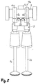
- Fig. 1
- eine variable Ventilsteuerung für einen 3-Ventil-Motor in Draufsicht,
- Fig. 2
- eine Ansicht von vorne auf die Ventilsteuerung,
- Fig. 3
- die Ventilsteuerung im Schnitt,
- Fig. 4 bis Fig. 6
- eine den Fig. 1 bis 3 entsprechende Darstellung einer Ventilsteuerung für einen 4-Ventil-Motor.
Claims (9)
- Variable Ventilsteuerung für eine Hubkolben-Brennkraftmaschine, die mindestens ein Einlaßventil und mindestens ein Auslaßventil aufweist,
mit einer Einlaß-Auslaß-Nockenwelle (2), auf der ein Einlaß-Öffnet-Nocken (4, 4a, 4b) zur Steuerung der Öffnungsfunktion des Einlaßventils (7a, 7b) sowie ein Auslaßnocken (6, 6a, 6b) zur Steuerung des Auslaßventils (8, 8a, 8b) angeordnet ist,
mit einer Einlaß-Schließt-Nockenwelle (3), auf der ein Einlaß-Schließt-Nocken (5, 5a, 5b) zur Steuerung der Schließfunktion des Einlaßventils (7a, 7b) angeordnet ist,
mit einem Einlaß-Betätigungshebel (9) zur Übertragung der Stellbewegung des Einlaß-Öffnet-Nockens (4, 4a, 4b) und des Einlaß-Schließt-Nockens (5, 5a, 5b) auf das Einlaßventil (7a, 7b),
mit einem Auslaß-Betätigungshebel (10) zur Übertragung der Stellbewegung des Auslaßnockens (6, 6a, 6b) auf das Auslaßventil (8, 8a, 8b),
und mit einer Einrichtung zur Änderung der Phasenlage zwischen den beiden Nockenwellen (2, 3),
dadurch gekennzeichnet,daß der Abstand der Mittelebenen (11, 11a, 11b; 27, 27a, 27b) von Einlaß-Schließt-Nocken (5, 5a, 5b) und Auslaßnocken (6, 6a, 6b) kleiner ist als die Summe von halber Auslaßnockenbreite (a/2) und halber Einlaß-Schließt-Nockenbreite (e/2),daß der die Nockenerhebung (14) umfassende Kopfkreis (15) des Auslaßnockens (6, 6a, 6b) sich mit dem entsprechenden Kopfkreis (17) des Einlaß-Schließt-Nockens (5, 5a, 5b) überschneidet, wobei die Nockenerhebungen (14, 16) des Auslaßnockens (6, 6a, 6b) und des Einlaß-Schließt-Nockens (5, 5a, 5b) berührungsfrei miteinander kämmen,und daß der Auslaßnocken (6, 6a, 6b) in der Projektion in Richtung der Nockenwellen-Längsachse (12) gesehen innerhalb der Kontur (13) des Einlaß-Öffnet-Nockens (4, 4a, 4b) liegt. - Ventilsteuerung nach Anspruch 1,
dadurch gekennzeichnet,
daß die Mittelebenen (11, 11a, 11b; 27, 27a, 27b) von Einlaß-Schließt-Nocken (5, 5a, 5b) und Auslaßnocken (6, 6a, 6b) eine gemeinsame Ebene bilden. - Ventilsteuerung nach Anspruch 1 oder 2,
dadurch gekennzeichnet,
daß die Bewegungsebene des Auslaßventils (8, 8a, 8b) mit der Mittelebene (27, 27a, 27b) des Auslaßnockens (6, 6a, 6b) zusammenfällt. - Ventilsteuerung nach einem der Ansprüche 1 bis 3,
dadurch gekennzeichnet,
daß dem Auslaßnocken (6, 6a, 6b) eine am Auslaß-Betätigungshebel (10) gelagerte Rolle (18) zugeordnet ist, über die die Nockenkontur (19) des Auslaßnockens (6, 6a, 6b) auf den Auslaß-Betätigungshebel (10) übertragbar ist. - Ventilsteuerung nach einem der Ansprüche 1 bis 4,
dadurch gekennzeichnet,
daß den Einlaßnocken (4, 4a, 4b, 5, 5a, 5b) ein am Einlaß-Betätigungshebel (9) verschieblich angeordnetes Rollenpaket (20) zugeordnet ist, über das die Nockenkontur (13, 21) der Einlaßnocken (4, 4a, 4b, 5, 5a, 5b) auf den Einlaß-Betätigungshebel (9) übertragbar ist. - Ventilsteuerung nach einem der Ansprüche 1 bis 5,
dadurch gekennzeichnet, t
daß zwei Einlaß-Öffnet-Nocken (4a, 4b) vorgesehen sind, die beidseitig des einzelnen Auslaßnockens (6) auf der Einlaß-Auslaß-Nockenwelle (2) angeordnet sind. - Ventilsteuerung nach einem der Ansprüche 1 bis 5,
dadurch gekennzeichnet,
daß zwei Auslaßnocken (6a, 6b) und zwei Einlaß-Schließt-Nocken (5a, 5b) vorgesehen sind, wobei jeweils ein Auslaßnocken (6a; 6b) und ein Einlaß-Schließt-Nocken (5a; 5b) in gemeinsamen Mittelebenen (11a; 11b, 27a; 27b) angeordnet sind. - Ventilsteuerung nach Anspruch 7,
dadurch gekennzeichnet,
daß mittig zwischen den beiden Auslaßnocken (6a, 6b) der Einlaß-Öffnet-Nocken (4) angeordnet ist. - Ventilsteuerung nach einem der Ansprüche 1 bis 8,
dadurch gekennzeichnet,
daß der Einlaß-Betätigungshebel (9) und der Auslaß-Betätigungshebel (10) an einer gemeinsamen Hebelachse (22) gelagert sind.
Applications Claiming Priority (2)
| Application Number | Priority Date | Filing Date | Title |
|---|---|---|---|
| DE19814800 | 1998-04-02 | ||
| DE19814800A DE19814800A1 (de) | 1998-04-02 | 1998-04-02 | Variable Ventilsteuerung für eine Hubkolben-Brennkraftmaschine |
Publications (2)
| Publication Number | Publication Date |
|---|---|
| EP0947672A2 true EP0947672A2 (de) | 1999-10-06 |
| EP0947672A3 EP0947672A3 (de) | 2000-08-02 |
Family
ID=7863367
Family Applications (1)
| Application Number | Title | Priority Date | Filing Date |
|---|---|---|---|
| EP99104523A Withdrawn EP0947672A3 (de) | 1998-04-02 | 1999-03-06 | Variable Ventilsteuerung für eine Hubkolben-Brennkraftmaschine |
Country Status (3)
| Country | Link |
|---|---|
| US (1) | US6058896A (de) |
| EP (1) | EP0947672A3 (de) |
| DE (1) | DE19814800A1 (de) |
Cited By (1)
| Publication number | Priority date | Publication date | Assignee | Title |
|---|---|---|---|---|
| EP2031196A2 (de) | 2007-08-29 | 2009-03-04 | Volkswagen AG | Brennkraftmaschine |
Families Citing this family (2)
| Publication number | Priority date | Publication date | Assignee | Title |
|---|---|---|---|---|
| EP1306527B1 (de) * | 2001-10-25 | 2008-01-02 | Ford Global Technologies, LLC | Dieselmotor mit variablem Kompressionsverhältnis |
| DE102014003466A1 (de) * | 2014-03-11 | 2015-09-17 | Meta Motoren- Und Energie-Technik Gmbh | Vorrichtung und Verfahren zur variablen Steuerung eines Ventils einer Brennkraftmaschine |
Citations (1)
| Publication number | Priority date | Publication date | Assignee | Title |
|---|---|---|---|---|
| DE19600536A1 (de) | 1996-01-09 | 1997-07-10 | Meta Motoren Energietech | Vorrichtung zur variablen Steuerung eines Einlaßventils |
Family Cites Families (14)
| Publication number | Priority date | Publication date | Assignee | Title |
|---|---|---|---|---|
| BE885719A (nl) * | 1980-10-15 | 1981-02-02 | Goederen Arie C De | Zuigerverbrandingsmotor met regelbare klepopeningsduur |
| DE3217203A1 (de) * | 1981-05-15 | 1982-12-02 | Honda Giken Kogyo K.K., Tokyo | Variable ventilsteuerung |
| US4546735A (en) * | 1984-01-23 | 1985-10-15 | Southwest Research Institute | Valve actuator |
| DE3402605A1 (de) * | 1984-01-26 | 1985-08-01 | Audi AG, 8070 Ingolstadt | Ventilsteuerung fuer eine hubkolben-brennkraftmaschine |
| GB2180597A (en) * | 1985-09-13 | 1987-04-01 | Frederick Arthur Summerlin | Valve control |
| US4862845A (en) * | 1988-05-10 | 1989-09-05 | Borg-Warner Transmission And Engine Components Corporation | Variable camshaft timing system |
| GB9018558D0 (en) * | 1990-08-23 | 1990-10-10 | Ricardo Group Plc | Valve gear for internal combustion engines |
| US5052350A (en) * | 1990-11-02 | 1991-10-01 | King Brian T | Device to combine the motions of two camlobes differentially phased |
| ATE158058T1 (de) * | 1991-04-24 | 1997-09-15 | Donald Charles Wride | Ventilantriebsvorrichtung |
| US5241928A (en) * | 1992-03-13 | 1993-09-07 | Suzuki Motor Corp. | Movable valve device for engine |
| US5586527A (en) * | 1992-12-30 | 1996-12-24 | Meta Motoren-Und Energie-Technik Gmbh | Device for the variable control of the valves of internal combustion engines, more particularly for the throttle-free load control of 4-stroke engines |
| DE4301453C2 (de) * | 1993-01-20 | 1995-01-05 | Meta Motoren Energietech | Variable Ventilsteuerung von Brennkraftmaschinen |
| DE4322480C2 (de) * | 1993-07-06 | 1996-05-02 | Meta Motoren Energietech | Vorrichtung zur variablen Ventilsteuerung von Brennkraftmaschinen |
| DE19701202A1 (de) * | 1997-01-15 | 1998-07-23 | Daimler Benz Ag | Variable Ventilsteuerung für Brennkraftmaschinen |
-
1998
- 1998-04-02 DE DE19814800A patent/DE19814800A1/de not_active Ceased
-
1999
- 1999-03-06 EP EP99104523A patent/EP0947672A3/de not_active Withdrawn
- 1999-03-29 US US09/280,937 patent/US6058896A/en not_active Expired - Fee Related
Patent Citations (1)
| Publication number | Priority date | Publication date | Assignee | Title |
|---|---|---|---|---|
| DE19600536A1 (de) | 1996-01-09 | 1997-07-10 | Meta Motoren Energietech | Vorrichtung zur variablen Steuerung eines Einlaßventils |
Cited By (2)
| Publication number | Priority date | Publication date | Assignee | Title |
|---|---|---|---|---|
| EP2031196A2 (de) | 2007-08-29 | 2009-03-04 | Volkswagen AG | Brennkraftmaschine |
| DE102007040697A1 (de) | 2007-08-29 | 2009-03-05 | Volkswagen Ag | Brennkraftmaschine |
Also Published As
| Publication number | Publication date |
|---|---|
| EP0947672A3 (de) | 2000-08-02 |
| US6058896A (en) | 2000-05-09 |
| DE19814800A1 (de) | 1999-10-14 |
Similar Documents
| Publication | Publication Date | Title |
|---|---|---|
| EP0659232B1 (de) | Verfahren und vorrichtung zur variablen steuerung eines ventils einer brennkraftmaschine | |
| DE10148177B4 (de) | Ventiltrieb mit Ventilhubumschaltung für die Gaswechselventiele eines 4-Takt-Verbrennungsmotors | |
| DE4301453C2 (de) | Variable Ventilsteuerung von Brennkraftmaschinen | |
| DE10006018B4 (de) | Variabler Ventiltrieb zur Laststeuerung einer fremdgezündeten Brennkraftmaschine | |
| DE3302194A1 (de) | Vorrichtung zur betaetigung von einlass- und auslassventilen bei einer brennkraftmaschine | |
| EP0521412A1 (de) | Brennkraftmaschine mit einem Schlepphebelventiltrieb | |
| DE19851045A1 (de) | Vorrichtung für variable Ventilbetätigung | |
| WO2006092312A1 (de) | Variable mechanische ventilsteuerung einer brennkraftmaschine | |
| DE10312961C5 (de) | Vorrichtung zur variablen Betätigung der Gaswechselventile von Verbrennungsmotoren | |
| DE19701203A1 (de) | Variable Ventilsteuerung für Brennkraftmaschinen | |
| EP0947672A2 (de) | Variable Ventilsteuerung für eine Hubkolben-Brennkraftmaschine | |
| EP0909881A2 (de) | Vorrichtung zur variablen Ventilsteuerung für eine Brennkraftmaschine | |
| DE19701202A1 (de) | Variable Ventilsteuerung für Brennkraftmaschinen | |
| DE10312959B4 (de) | Vorrichtung zur variablen Betätigung der Gaswechselventile von Verbrennungsmotoren | |
| EP0865566A2 (de) | Ventiltrieb einer brennkraftmaschine | |
| EP0352580B1 (de) | Betätigungsvorrichtung für Ventile einer Brennkraftmaschine | |
| DE19745761A1 (de) | Variable Ventilsteuerung für Hubkolben-Brennkraftmaschinen | |
| EP2201223B1 (de) | Brennkraftmaschine mit zumindest einem zylinder mit einer drehsteifen nockenwelle | |
| DE4300684C2 (de) | Ventiltrieb zur variablen Steuerung von Brennkraftmaschinen | |
| EP1608852B1 (de) | Vorrichtung zur variablen bet tigung der gaswechselventile v on verbrennungsmotoren und verfahren zum betreiben einer derartigen vorrichtung | |
| DE10137072A1 (de) | Vorrichtung zum Antrieb von wenigstens einem Ventil eines Hubkolbenmotors | |
| EP0686756A1 (de) | Ventiltrieb mit variabler Steuerung der Ventilöffnungswinkel | |
| EP1128029B1 (de) | Variable Ventilsteuerung für Hubkolben-Brennkraftmaschinen | |
| EP1288451B1 (de) | Zylinderkopf für eine Hubkolben-Brennkraftmaschine mit einer hubvariablen Ventilsteuerung | |
| EP1619362A2 (de) | Ventiltrieb einer Brennkraftmaschine |
Legal Events
| Date | Code | Title | Description |
|---|---|---|---|
| PUAI | Public reference made under article 153(3) epc to a published international application that has entered the european phase |
Free format text: ORIGINAL CODE: 0009012 |
|
| AK | Designated contracting states |
Kind code of ref document: A2 Designated state(s): DE FR GB IT |
|
| AX | Request for extension of the european patent |
Free format text: AL;LT;LV;MK;RO;SI |
|
| PUAL | Search report despatched |
Free format text: ORIGINAL CODE: 0009013 |
|
| AK | Designated contracting states |
Kind code of ref document: A3 Designated state(s): AT BE CH CY DE DK ES FI FR GB GR IE IT LI LU MC NL PT SE |
|
| AX | Request for extension of the european patent |
Free format text: AL;LT;LV;MK;RO;SI |
|
| RIC1 | Information provided on ipc code assigned before grant |
Free format text: 7F 01L 13/00 A, 7F 01L 1/26 B |
|
| 17P | Request for examination filed |
Effective date: 20000707 |
|
| AKX | Designation fees paid |
Free format text: DE FR GB IT |
|
| STAA | Information on the status of an ep patent application or granted ep patent |
Free format text: STATUS: THE APPLICATION IS DEEMED TO BE WITHDRAWN |
|
| 18D | Application deemed to be withdrawn |
Effective date: 20011002 |