US6058896A - Variable valve control for an internal combustion engine - Google Patents
Variable valve control for an internal combustion engine Download PDFInfo
- Publication number
- US6058896A US6058896A US09/280,937 US28093799A US6058896A US 6058896 A US6058896 A US 6058896A US 28093799 A US28093799 A US 28093799A US 6058896 A US6058896 A US 6058896A
- Authority
- US
- United States
- Prior art keywords
- cam
- inlet
- outlet
- inlet valve
- valve
- Prior art date
- Legal status (The legal status is an assumption and is not a legal conclusion. Google has not performed a legal analysis and makes no representation as to the accuracy of the status listed.)
- Expired - Fee Related
Links
Images


Classifications
-
- F—MECHANICAL ENGINEERING; LIGHTING; HEATING; WEAPONS; BLASTING
- F01—MACHINES OR ENGINES IN GENERAL; ENGINE PLANTS IN GENERAL; STEAM ENGINES
- F01L—CYCLICALLY OPERATING VALVES FOR MACHINES OR ENGINES
- F01L13/00—Modifications of valve-gear to facilitate reversing, braking, starting, changing compression ratio, or other specific operations
- F01L13/0015—Modifications of valve-gear to facilitate reversing, braking, starting, changing compression ratio, or other specific operations for optimising engine performances by modifying valve lift according to various working parameters, e.g. rotational speed, load, torque
- F01L13/0036—Modifications of valve-gear to facilitate reversing, braking, starting, changing compression ratio, or other specific operations for optimising engine performances by modifying valve lift according to various working parameters, e.g. rotational speed, load, torque the valves being driven by two or more cams with different shape, size or timing or a single cam profiled in axial and radial direction
- F01L13/0047—Modifications of valve-gear to facilitate reversing, braking, starting, changing compression ratio, or other specific operations for optimising engine performances by modifying valve lift according to various working parameters, e.g. rotational speed, load, torque the valves being driven by two or more cams with different shape, size or timing or a single cam profiled in axial and radial direction the movement of the valves resulting from the sum of the simultaneous actions of at least two cams, the cams being independently variable in phase in respect of each other
Definitions
- the invention relates to a variable valve control for a piston internal combustion engine with at least one inlet valve and at least one outlet valve, an inlet-outlet camshaft including an inlet valve opening cam for controlling the opening time of the inlet valve, an outlet cam for operating the outlet valve, an inlet valve closing camshaft having an inlet valve closing cam for controlling the closing time of the inlet valve, an inlet valve operating lever for transferring the control motion of the inlet valve opening cam and of the inlet valve closing cam to the inlet valve, an outlet valve operating lever for transmitting the control motion of the outlet valve operating cam to the outlet valve and a device for changing the phase relationship between the two camshafts.
- Such an arrangement is known, for example, from DE 196 00 536 A1.
- the arrangement permits the reduction of exhaust gas emissions and also an increase of the engine torque. By reducing the energy needed for the gas exchange the fuel consumption of the engine can also be reduced. Furthermore, there is no need for a throttle valve in the intake duct of the engine.
- the arrangement comprises two camshafts, one including an inlet cam for controlling the opening functions of the inlet valve and an exhaust cam for controlling the exhaust valve.
- the other camshaft includes an inlet valve closing cam for controlling the closing time of the inlet valve.
- the inlet valve opening and closing cams act in an additive fashion and together determine the opening lift and opening duration of the inlet valve. With a device for changing the phase relation between the two camshafts, the relative angle between the two camshafts can be controlled in order to adjust the opening lift and opening duration of the inlet valve.
- the inlet valve opening cam and the inlet valve closing cam are disposed in a common plane so that the rotation of the inlet valve opening cam on the first cam shaft and the rotation of the inlet valve closing cam on the second cam shaft occur in the same plane of movement.
- the exhaust cam which is arranged on the side of the inlet valve opening cam is displaced axially from the exhaust valve which requires the use of an offset valve opening lever: the contact point between the exhaust cam and the exhaust valve operating lever is disposed outside the center plane of the exhaust valve, that is, outside a plane extending normal to the camshaft and through the exhaust valve axis.
- This asymmetrical arrangement generates bending forces, which accelerate wear and detrimentally affect precise motion transmission between the cam and the valve.
- an inlet valve closing cam and an exhaust valve operating cam are disposed essentially in radial alignment and the camshafts are arranged so close together that the top portion circles of the two cams are overlapping but cooperating angularly so that, when the top portion of one of the adjacent cams is directed toward the other cam the top portion of the other cam is directed away from the one cam.
- the distance between the center planes of inlet valve closing cam and the outlet valve operating cam is only very small, that is, it is smaller then the sum of half the widths of the inlet valve closing cam and the exhaust valve operating cam so that, in an axial view, both cams overlap. Furthermore, the distance between the two cam shafts and the cams are so dimensioned that the high cam portion circles enclosing the cams of the two cam shafts overlap and the high level portions of the inlet valve closing and the exhaust valve operating cams are received in the respective low level portions of the opposite cams without contact.
- the distance between the two cam shafts can be very small while the cam movements of the inlet valve closing cam and of the exhaust valve operating cam do not conflict.
- a compact valve operating arrangement of short axial length can be provided since the inlet valve closing cam and the exhaust valve operating cam can be disposed at the same axial location.
- Another advantage resides in the fact that, inspite of the short axial length, the individual cams can be sufficiently wide to accommodate the valve operating forces so that a high operational durability and reliability are achieved.
- the center planes of the exhaust cams and the inlet valve closing cams have only a small distance from each other the member of operating planes for the inlet and exhaust cams is also reduced.
- the center planes of the exhaust cam and the operating plane of the exhaust valve essentially coincide so that the operating motion of the exhaust cam is transmitted to the exhaust valve without axial offset and the force transmitting levers are not subjected to twisting torque forces.
- the exhaust valve operating lever can then be simple since it is straight and extends in a plane normal to the camshaft axis in which also the exhaust valve is disposed.
- the exhaust valve operating cam is disposed, in an axial projection of the inlet valve opening and outlet valve operating cam within the contour of the inlet valve opening cam. This prevents that the inlet valve opening timing is affected in any way by the outlet valve operating cam.
- the arrangement is suitable for internal combustion engines with three valves per cylinder and also for engine with four valves per cylinder.
- the exhaust valve operating cam is disposed in the middle between two inlet valve opening cams on the inlet-outlet cam shaft.
- the outlet valve operating cam is disposed in the same center plane with the respective inlet valve closing cam on the other (inlet valve closing) camshaft.
- the two outlet valve operating cams are arranged directly opposite, that is in the same plane with, the respective inlet valve closing cams on the other cam shaft.
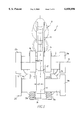
- FIG. 1 is a top view of a variable valve control arrangement for an engine with three valves per cylinder,
- FIG. 2 is a side view of the valve control arrangement
- FIG. 3 shows the valve control arrangement in a cross-sectional view
- FIGS. 4, 5, and 6 are views corresponding to those of FIGS. 1, 2, and 3 showing a variable valve control arrangement for an engine with four valves per cylinder.
- the variable valve control arrangement 1 controls the inlet and outlet valves of an internal combustion engine with three valves per cylinder.
- the arrangement comprises two parallel camshafts, an inlet-outlet camshaft 2 and an inlet valve closing camshaft 3, for controlling the operation of the valves and specifically the inlet valves 7a, 7b.
- the inlet-outlet cam shaft 2 also controls the outlet valves 8.
- a device not shown herein, particularly a coupler drive the relative angular positions of the two cam shafts 2, 3 can be changed in order to control the opening duration and the opening lift of the inlet valves 7a, 7b. With such a valve control arrangement, there is no need for a throttle valve in the intake duct of the internal combustion engine.
- the inlet-outlet camshaft 2 as shown in FIGS. 1-3 includes two inlet valve opening cams 4a, 4b, which cooperate with an inlet valve closing cam 5 on the parallel inlet valve closing camshaft 3 in an opening time adding procedure.
- the inlet valve opening cams 4a, 4b determine the opening movement of the inlet valves while the inlet valve closing cam 5 controls the closing movement of the inlet valves.
- the control motion of the inlet cams 4a, 4b 5 is transmitted to the inlet valves 7a, 7b by an inlet valve actuating lever.
- the two cam shafts 2, 3 are supported in bearing housings 23a, 23b, 24a, 24b.
- the inlet-outlet camshaft 2 includes an outlet valve operating cam 6 which is disposed centrally between the two inlet valve opening cams 4a, 4b.
- the control motion of the outlet valve operating cam 6 is transmitted to the outlet valve 8 by way of an outlet valve operating lever 10.
- the center plane 11 of the inlet valve closing cam 5 and the center plane 27 of the outlet valve operating cam 6 coincide or are at least so close together that they are spaced less than the sum of half the width e/2 of the inlet valve closing cam 5 and half the width a/2 of the outlet valve operating cam 6.
- the two center planes 11 and 27 coincide.
- the cams 5 and 6 rotate in the planes 11, 27 and the movement of the outlet valve 8 also occurs in the plane 11, 27.
- the motion transfer movement of exhaust valve operating lever occurs in the same plane 11, 27.
- the contour 19 of the outlet cam 6 in a projection in the direction of the longitudinal axis 12 of the cam shaft 2 is disposed within the contour 13 of the two inlet valve opening cams 4a, 4b. Also, the high point 14 of the outlet valve operating cam does not extend beyond the contour 13 of the inlet valve opening cams 4a, 4b.
- the high portion circle 15 centered on the axis of the inlet-outlet camshaft 2 and extending through the highest radial portion 14 of the outlet cam 6 intersects the high portion circle 17 centered on the axis of the inlet valve closing cam and extending through the highest radial portion 16 of the inlet valve closing cam. Over a part of its circumference, the high portion circle 17 coincides with the contour 21 of the inlet closing cam 5.
- the two cam high level portions 14 and 16 of the cams 6 and 5 mesh without contacting each other, that is, the high point portions of one cam extends toward the other cam when the low point portion of the other cam is disposed adjacent the one cam for any possible phase adjustment of the camshaft 3 with respect to cam shaft 2.
- the distance between the two camshafts can be as small as possible so that the whole valve operating mechanism can be small.
- the control motion of the exhaust valve operating cam 6 is transferred to the operating lever 10 by way of a roller 18, which is mounted on the operating lever 10.
- the control motion of the inlet valve operating cams is transmitted to the operating lever 9 by way of a roller arrangement 20, which is slidably supported on the inlet valve operating lever 9.
- the roller structure 20 is biased into contact with the inlet valve opening cams 4a, 4b two springs 25a, 25b (FIGS. 1 and 3).
- the springs 25a and 25b are supported on a web, which is mounted on the inlet valve operating lever 9.
- the inlet valve operating lever 9 and the outlet valve operating lever 10 are pivotally supported on a common lever shaft 22, which extends parallel to the axis of the camshafts 2, 3.
- FIGS. 4 to 6 show a variable valve control 1 for an internal combustion engine having four valves per cylinder.
- the components corresponding to particular components shown in FIGS. 1-3 are provided with the same reference numerals.
- Each cylinder of the internal combustion engine includes two inlet valves 7a, 7b and two outlet valves 8a, 8b.
- the inlet and outlet cams for operating the valves are arranged on the two parallel cam shafts 2, 3, whose angular position relative to each other is adjustable by a suitable phase control device.
- the inlet-outlet cam shaft 2 includes a central inlet valve opening cam 4, which, together with the axially spaced inlet valve closing cams 5a, 5b on the inlet valve closing cam shaft 3 controls the inlet valve opening times.
- the two inlet valve closing cams 5a, 5b are disposed axially offset from the inlet valve opening cam 4 in the center planes 11a, 11b.
- the center planes 27a, 27b of the exhaust valve operating cams 6a, 6b and the center planes 11a, 11b of the inlet valve closing cams 5a, 5b are disposed closely together such that the distance between the center planes 11a, 11b and 27a, 27b is less than the sum of half the width e/2 of the inlet valve closing cam and half the width a/2 of the outlet valve operating cams.
- the planes 11a and 27a and the planes 11b and 27b coincide (FIG. 4).
- the exhaust valve operating cams 6a and 6b are then arranged in radial alignment with the inlet valve closing cams 5a and 5b, respectively.
- the cam contour of the outlet valve operating cams that is, the motion of the outlet valve operating lever which is disposed on the same pivot shaft 22 as the inlet valve operating lever 9, is transferred via the rollers 18 mounted on the outlet valve operating levers 10 to the outlet valves 8a and 8b.
- the cam contour of the inlet valve operating cams 11a, 11b that is, the radial motion of the cams is transferred to the inlet valve operating lever 9 by way of the roller arrangement 20, which is biased into engagement with the inlet valve opening cam 4 by the springs 25a, 25b supported on the web 26.
- the motion of the inlet valve operating lever 9 is transferred to the inlet valves 7a, 7b.
- the cam shafts are arranged so closely together that the cam top portion circle 15 of the exhaust cam 6a, 6b overlaps the cam top portion circle 17 of the inlet valve closing cams 5a, 5b, whereby a highly compact valve drive is provided.
Landscapes
- Engineering & Computer Science (AREA)
- Mechanical Engineering (AREA)
- General Engineering & Computer Science (AREA)
- Valve Device For Special Equipments (AREA)
- Valve-Gear Or Valve Arrangements (AREA)
Applications Claiming Priority (2)
| Application Number | Priority Date | Filing Date | Title |
|---|---|---|---|
| DE19814800 | 1998-04-02 | ||
| DE19814800A DE19814800A1 (de) | 1998-04-02 | 1998-04-02 | Variable Ventilsteuerung für eine Hubkolben-Brennkraftmaschine |
Publications (1)
| Publication Number | Publication Date |
|---|---|
| US6058896A true US6058896A (en) | 2000-05-09 |
Family
ID=7863367
Family Applications (1)
| Application Number | Title | Priority Date | Filing Date |
|---|---|---|---|
| US09/280,937 Expired - Fee Related US6058896A (en) | 1998-04-02 | 1999-03-29 | Variable valve control for an internal combustion engine |
Country Status (3)
| Country | Link |
|---|---|
| US (1) | US6058896A (de) |
| EP (1) | EP0947672A3 (de) |
| DE (1) | DE19814800A1 (de) |
Cited By (1)
| Publication number | Priority date | Publication date | Assignee | Title |
|---|---|---|---|---|
| EP1306527A1 (de) * | 2001-10-25 | 2003-05-02 | Ford Global Technologies, Inc., A subsidiary of Ford Motor Company | Dieselmotor mit variablem Kompressionsverhältnis |
Families Citing this family (2)
| Publication number | Priority date | Publication date | Assignee | Title |
|---|---|---|---|---|
| DE102007040697A1 (de) | 2007-08-29 | 2009-03-05 | Volkswagen Ag | Brennkraftmaschine |
| DE102014003466A1 (de) * | 2014-03-11 | 2015-09-17 | Meta Motoren- Und Energie-Technik Gmbh | Vorrichtung und Verfahren zur variablen Steuerung eines Ventils einer Brennkraftmaschine |
Citations (13)
| Publication number | Priority date | Publication date | Assignee | Title |
|---|---|---|---|---|
| DE3402605A1 (de) * | 1984-01-26 | 1985-08-01 | Audi AG, 8070 Ingolstadt | Ventilsteuerung fuer eine hubkolben-brennkraftmaschine |
| US4535733A (en) * | 1981-05-15 | 1985-08-20 | Honda Giken Kogyo Kabushiki Kaisha | Variable valve timing apparatus |
| US4546735A (en) * | 1984-01-23 | 1985-10-15 | Southwest Research Institute | Valve actuator |
| US4862845A (en) * | 1988-05-10 | 1989-09-05 | Borg-Warner Transmission And Engine Components Corporation | Variable camshaft timing system |
| US5052350A (en) * | 1990-11-02 | 1991-10-01 | King Brian T | Device to combine the motions of two camlobes differentially phased |
| US5178105A (en) * | 1990-08-23 | 1993-01-12 | Ricardo Consulting Engineers Limited | Valve gear for internal combustion engines |
| DE4303574A1 (de) * | 1992-03-13 | 1993-09-23 | Suzuki Motor Co | |
| DE4322480A1 (de) * | 1993-07-06 | 1995-01-12 | Meta Motoren Energietech | Vorrichtung zur variablen Ventilsteuerung von Brennkraftmaschinen mit Ventilabschaltung |
| US5431132A (en) * | 1993-01-20 | 1995-07-11 | Meta Motoren-Und Energie-Technik Gmbh | Variable valve gear of internal combustion engines |
| US5555860A (en) * | 1991-04-24 | 1996-09-17 | Wride; Donald C. | Valve control mechanism |
| US5586527A (en) * | 1992-12-30 | 1996-12-24 | Meta Motoren-Und Energie-Technik Gmbh | Device for the variable control of the valves of internal combustion engines, more particularly for the throttle-free load control of 4-stroke engines |
| DE19600536A1 (de) * | 1996-01-09 | 1997-07-10 | Meta Motoren Energietech | Vorrichtung zur variablen Steuerung eines Einlaßventils |
| US5931127A (en) * | 1997-01-15 | 1999-08-03 | Daimler-Benz-A.G. | Variable valve timing mechanism for an internal combustion engine |
Family Cites Families (2)
| Publication number | Priority date | Publication date | Assignee | Title |
|---|---|---|---|---|
| BE885719A (nl) * | 1980-10-15 | 1981-02-02 | Goederen Arie C De | Zuigerverbrandingsmotor met regelbare klepopeningsduur |
| GB2180597A (en) * | 1985-09-13 | 1987-04-01 | Frederick Arthur Summerlin | Valve control |
-
1998
- 1998-04-02 DE DE19814800A patent/DE19814800A1/de not_active Ceased
-
1999
- 1999-03-06 EP EP99104523A patent/EP0947672A3/de not_active Withdrawn
- 1999-03-29 US US09/280,937 patent/US6058896A/en not_active Expired - Fee Related
Patent Citations (14)
| Publication number | Priority date | Publication date | Assignee | Title |
|---|---|---|---|---|
| US4535733A (en) * | 1981-05-15 | 1985-08-20 | Honda Giken Kogyo Kabushiki Kaisha | Variable valve timing apparatus |
| US4546735A (en) * | 1984-01-23 | 1985-10-15 | Southwest Research Institute | Valve actuator |
| DE3402605A1 (de) * | 1984-01-26 | 1985-08-01 | Audi AG, 8070 Ingolstadt | Ventilsteuerung fuer eine hubkolben-brennkraftmaschine |
| US4862845A (en) * | 1988-05-10 | 1989-09-05 | Borg-Warner Transmission And Engine Components Corporation | Variable camshaft timing system |
| US5178105A (en) * | 1990-08-23 | 1993-01-12 | Ricardo Consulting Engineers Limited | Valve gear for internal combustion engines |
| US5052350A (en) * | 1990-11-02 | 1991-10-01 | King Brian T | Device to combine the motions of two camlobes differentially phased |
| US5555860A (en) * | 1991-04-24 | 1996-09-17 | Wride; Donald C. | Valve control mechanism |
| DE4303574A1 (de) * | 1992-03-13 | 1993-09-23 | Suzuki Motor Co | |
| US5586527A (en) * | 1992-12-30 | 1996-12-24 | Meta Motoren-Und Energie-Technik Gmbh | Device for the variable control of the valves of internal combustion engines, more particularly for the throttle-free load control of 4-stroke engines |
| US5431132A (en) * | 1993-01-20 | 1995-07-11 | Meta Motoren-Und Energie-Technik Gmbh | Variable valve gear of internal combustion engines |
| DE4322480A1 (de) * | 1993-07-06 | 1995-01-12 | Meta Motoren Energietech | Vorrichtung zur variablen Ventilsteuerung von Brennkraftmaschinen mit Ventilabschaltung |
| US5592906A (en) * | 1993-07-06 | 1997-01-14 | Meta Motoren- Und Energie-Technik Gmbh | Method and device for variable valve control of an internal combustion engine |
| DE19600536A1 (de) * | 1996-01-09 | 1997-07-10 | Meta Motoren Energietech | Vorrichtung zur variablen Steuerung eines Einlaßventils |
| US5931127A (en) * | 1997-01-15 | 1999-08-03 | Daimler-Benz-A.G. | Variable valve timing mechanism for an internal combustion engine |
Cited By (1)
| Publication number | Priority date | Publication date | Assignee | Title |
|---|---|---|---|---|
| EP1306527A1 (de) * | 2001-10-25 | 2003-05-02 | Ford Global Technologies, Inc., A subsidiary of Ford Motor Company | Dieselmotor mit variablem Kompressionsverhältnis |
Also Published As
| Publication number | Publication date |
|---|---|
| EP0947672A3 (de) | 2000-08-02 |
| EP0947672A2 (de) | 1999-10-06 |
| DE19814800A1 (de) | 1999-10-14 |
Similar Documents
| Publication | Publication Date | Title |
|---|---|---|
| US5988125A (en) | Variable valve actuation apparatus for engine | |
| EP1905967B1 (de) | Verbrennungsmotor mit variabler Ventilhebung | |
| US7603973B2 (en) | Variable mechanical valve control for an internal combustion engine | |
| US5996540A (en) | Variable valve timing and lift system | |
| US5732669A (en) | Valve control for an internal combustion engine | |
| US6837198B2 (en) | Variable valve distributor for load-controlling a spark-ignited internal combustion engine | |
| US7073470B2 (en) | Variable valve apparatus of internal combustion engine | |
| US6988473B2 (en) | Variable valve actuation mechanism having an integrated rocker arm, input cam follower and output cam body | |
| US6295958B2 (en) | Linkless variable valve actuation mechanism | |
| US6386161B2 (en) | Cam link variable valve mechanism | |
| US7156059B2 (en) | Variable valve train apparatus for an internal combustion engine | |
| US6481397B2 (en) | Variable valve drive system for an internal combustion engine | |
| US6058896A (en) | Variable valve control for an internal combustion engine | |
| JP2005282573A (ja) | 可変リフト装置 | |
| US6009842A (en) | Fuel injection system for a multicylinder internal combustion engine with a fuel supply line serving as a high pressure storage device | |
| US7665434B2 (en) | Internal combustion engine with continuous variable valve lift system | |
| JP4031973B2 (ja) | 内燃機関の可変動弁装置 | |
| KR20000071212A (ko) | 밸브 작동기구 | |
| US6655330B2 (en) | Offset variable valve actuation mechanism | |
| US7159550B2 (en) | Variable valve train of internal combustion engine | |
| JP4085886B2 (ja) | 内燃機関の可変動弁装置 | |
| JP4328966B2 (ja) | 内燃機関の可変動弁装置 | |
| JP2005264840A (ja) | 内燃機関の可変動弁装置 | |
| JP2008075623A (ja) | 開弁特性可変型内燃機関 |
Legal Events
| Date | Code | Title | Description |
|---|---|---|---|
| AS | Assignment |
Owner name: DAIMLER CHRYSLER AG, GERMANY Free format text: ASSIGNMENT OF ASSIGNORS INTEREST;ASSIGNOR:KRAUTH, DIETER;REEL/FRAME:009860/0942 Effective date: 19990316 |
|
| FEPP | Fee payment procedure |
Free format text: PAYOR NUMBER ASSIGNED (ORIGINAL EVENT CODE: ASPN); ENTITY STATUS OF PATENT OWNER: LARGE ENTITY |
|
| REMI | Maintenance fee reminder mailed | ||
| LAPS | Lapse for failure to pay maintenance fees | ||
| FP | Lapsed due to failure to pay maintenance fee |
Effective date: 20040509 |
|
| STCH | Information on status: patent discontinuation |
Free format text: PATENT EXPIRED DUE TO NONPAYMENT OF MAINTENANCE FEES UNDER 37 CFR 1.362 |