EP0947775A2 - Zweiteiliger Halter für Steinplatten - Google Patents
Zweiteiliger Halter für Steinplatten Download PDFInfo
- Publication number
- EP0947775A2 EP0947775A2 EP99106400A EP99106400A EP0947775A2 EP 0947775 A2 EP0947775 A2 EP 0947775A2 EP 99106400 A EP99106400 A EP 99106400A EP 99106400 A EP99106400 A EP 99106400A EP 0947775 A2 EP0947775 A2 EP 0947775A2
- Authority
- EP
- European Patent Office
- Prior art keywords
- tab
- bolt
- holder
- hook
- holder according
- Prior art date
- Legal status (The legal status is an assumption and is not a legal conclusion. Google has not performed a legal analysis and makes no representation as to the accuracy of the status listed.)
- Withdrawn
Links
Images


Classifications
-
- F—MECHANICAL ENGINEERING; LIGHTING; HEATING; WEAPONS; BLASTING
- F23—COMBUSTION APPARATUS; COMBUSTION PROCESSES
- F23M—CASINGS, LININGS, WALLS OR DOORS SPECIALLY ADAPTED FOR COMBUSTION CHAMBERS, e.g. FIREBRIDGES; DEVICES FOR DEFLECTING AIR, FLAMES OR COMBUSTION PRODUCTS IN COMBUSTION CHAMBERS; SAFETY ARRANGEMENTS SPECIALLY ADAPTED FOR COMBUSTION APPARATUS; DETAILS OF COMBUSTION CHAMBERS, NOT OTHERWISE PROVIDED FOR
- F23M5/00—Casings; Linings; Walls
- F23M5/08—Cooling thereof; Tube walls
-
- F—MECHANICAL ENGINEERING; LIGHTING; HEATING; WEAPONS; BLASTING
- F23—COMBUSTION APPARATUS; COMBUSTION PROCESSES
- F23M—CASINGS, LININGS, WALLS OR DOORS SPECIALLY ADAPTED FOR COMBUSTION CHAMBERS, e.g. FIREBRIDGES; DEVICES FOR DEFLECTING AIR, FLAMES OR COMBUSTION PRODUCTS IN COMBUSTION CHAMBERS; SAFETY ARRANGEMENTS SPECIALLY ADAPTED FOR COMBUSTION APPARATUS; DETAILS OF COMBUSTION CHAMBERS, NOT OTHERWISE PROVIDED FOR
- F23M5/00—Casings; Linings; Walls
- F23M5/04—Supports for linings
Definitions
- the invention relates to a holder for stone slabs of an incinerator for example a waste incineration plant, with a support for supporting a stone slab and a plate-shaped one that can be hung upright in the carrier Tab to hold the framed stone slab.
- the boundary wall of a waste incinerator usually consists of a pipe wall and curtain-resistant, fire-resistant stone slabs, for example Silicon carbide.
- the connecting the individual parallel tubes Metal wall sections are also called tubular fins, to which massive holders of the type mentioned at the beginning (G 90 16 206.4) to support and maintain the Stone slabs are attached. Because the furnace wall a variety of stone slabs shows, the welding of the numerous supports proves to be a very time-consuming operation.
- the holder recesses can be provided, in which the tabs for the purpose Maintaining the stone slabs are embedded. Such recesses reduce the plate thickness required to protect the pipe wall.
- the trapezoidal support the holder according to DE-40 07 662 C1 is difficult to attach to the pipe fins weld on.
- the holder requires large recesses in the Stone slabs.
- the invention has for its object to the holder mentioned improve.
- the Carrier is a bolt, one at its end facing away from the welding foot has upright hook for reaching behind the hooked tab, and that the tab has two aprons, which with the tab attached under the bolts reach down. Since the shape of the beam is reduced to a bolt, the required cutouts in the stone slabs are kept smaller, what improves its protective function and reduces the risk of corrosion of the pipe wall. Furthermore, there is the great advantage that the carrier in the stud welding process the metal wall can be welded on, fixing the working time the numerous supports on the metal wall are significantly shortened. The one from the tab descending aprons are sufficient, the stone slab from above against the Maintain metal wall that is below the stone slab supported by the bolt located.
- the bolt has one in front of the hook Notch corresponding to the strength of the tab. This will win the tab a defined position on the bolt during assembly, so that the Placing the stone slab on the bolt is facilitated. They are useful opposite side parts of the tab relative to the die The middle part of the flap connecting the side parts is folded, which results in a Reduction of the lateral recesses of the stone slab can be achieved. Further it is recommended that the hooked tab is not or at least not significantly higher than the height of the hook. This measure also leaves the cutout in the stone slab is small for the tab.
- the hook in the of the chamfered side panels is defined space and the aprons are not reach further under the bolt than the tab rises above the bolt, can the recesses required for the holder in the stone slabs above and below are shaped symmetrically, which is the manufacture of the stone slabs simplified and counteracts the risk of cracking in the stone slabs.
- the welding of the bolt to the metal wall must do the considerable thing Weight of the stone slabs without risk of breakage despite the eminent thermal Can take a load.
- a bolt that is in preferred embodiment of the invention as a cross-sectional shape an upright represents a standing rectangle, in particular of 15 x 8 mm. It is also recommended the part of the recesses in the stone slabs on the combustion chamber side a wool, a ceramic tile or a glued, air-permeable Lining the thermal insulation layer, thereby additionally a scaling of the Counteract holder.
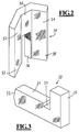
- the holder 1 consists of a bolt 20 and one suspended in the bolt 20 Tab 30.
- the bolt 20 has a shaft 21 with a front welding foot 22 and an upright hook at the end facing away from the welding foot 22 25 on.
- the cross-sectional shape of the shaft 21 is an upright rectangle with the external dimensions 15 x 8 mm.
- the shaft 21 has a Notch 23, the width of the thickness of which is taken in the longitudinal direction of the shaft Middle part 35 corresponds to the tab 30.
- the essentially plate-shaped tab 30 consists of two opposite side parts 32, 34 and the middle part 35 connecting them.
- the side parts 32, 34 are relative to the central part 35 in the same direction and in essentially folded by the same amount.
- the middle part 35 has from its underside a cutout 36 of a width that the thickness of the Shaft 21 corresponds, that is little larger than 8 mm. This makes everyone Side apron 37, 39 each formed a descending.
- the Tab 30 hung in the pin 20 in the manner shown in FIG. 1, the middle part is held in the cutout 36 and the two side parts 32, 34 define a space between them in which the hook 25 is recorded.
- the aprons 37, 39 then extend so far under the shaft 21, how the middle part 35 and the two side parts 32, 34 over the shaft 21 raise. It can also be seen from FIG. 1 that the side parts 32, 34 and the middle part 35 are only slightly higher than the hook 25.
- the shaft 21 with its welding foot 22 through Stud welding is welded to the tube fin 3, which only takes a short time.
- the tab 30 can then be used to prepare for the construction of the stone slab wall be hung in the holder in front of the pipe wall 2 as explained.
- the upper stone slab 6 has a recess 15 opening approximately in the middle of its underside, in which the upper part of the tab 30 and the hook 25 are to be accommodated. How Figure 5 shows, the recess 15 has a width which is slightly larger than that Width of the tab 30.
- a cutout 18 in the underside of the stone slab 6, which sits on the shaft 21, extends from the inside 11 to the recess 15. The depth of the cutout 18 can be approximately half the height of the shaft 21 correspond.
- the lower stone slab 7 has an opening approximately in the middle of its upper side Recess 16 in which the aprons 37 and 39 find space. Like Figure 6 shows, the recess 16 has a width which is slightly larger than the width of the Tab 30. A cutout 13 in that receives the lower half of the shaft 21 the top of the stone slab 7 extends from the inside 17 to Recess 16.
- the cutout 18 and the recess 15 are symmetrical to the cutout 13 and the recess 16.
- the aprons 37 and 39 When building the stone slab wall, the aprons 37 and 39 initially hold the lower stone slab 7 by their engagement in the recess 16 against the Pipe wall 2 at. In the combustion chamber-side part 14 of the recess 16 becomes a wool or the like air-permeable thermal insulation material introduced, which is on the side facing away from the tube wall 2 of the Hook 25 and the aprons 37, 39 is located. Then the upper stone slab 6 placed on the shaft 21 of the holder, so that the cutout 18 on the latter rests. The hook 25 extending into the recess 15 and the upper part of the Tab 30 keep the stone slab 6.
- Recess 15 is also a wool or the like air permeable Thermal insulation material introduced, which is on the pipe wall 2 facing away from the hook 25 and the aprons 37, 39. Finally the outer joint 10 between the upper stone slab 6 and the lower stone slab 7 groomed.
Landscapes
- Engineering & Computer Science (AREA)
- Chemical & Material Sciences (AREA)
- Combustion & Propulsion (AREA)
- Mechanical Engineering (AREA)
- General Engineering & Computer Science (AREA)
- Furnace Housings, Linings, Walls, And Ceilings (AREA)
- Packaging Of Annular Or Rod-Shaped Articles, Wearing Apparel, Cassettes, Or The Like (AREA)
Abstract
Description
- Figur 1
- eine perspektivische Ansicht eines mit den Merkmalen der Erfindung ausgestattenen Halters;
- Figur 2
- eine perspektivische Ansicht der Lasche zum Halter nach Figur 1;
- Figur 3
- eine perspektivische Ansicht des Bolzens zum Halter nach Figur 1;
- Figur 4
- einen Vertikalschnitt durch eine Ofenwand mit angeschweißtem Halter nach Figur 1;
- Figur 5
- einen Schnitt durch die Ofenwand nach Figur 4 längs der Linie A - A; und
- Figur 6
- einen Schnitt durch die Ofenwand nach Figur 4 längs der Linie B - B.
Claims (7)
- Halter für Steinplatten (6, 7) eines Verbrennungsofens beispielsweise einer Müllverbrennungsanlage, mit einem Träger (20) zum Unterfassen einer Steinplatte (6) und einer in den Träger aufrecht einhängbaren, plattenförmigen Lasche (30) zum Beihalten der unterfaßten Steinplatte (6), dadurch gekennzeichnet, daß der Träger ein Bolzen (20) ist, der an seinem dem Schweißfuß (22) abgewandten Ende einen aufrechten Haken (25) zum Hintergreifen der eingehängten Lasche (30) aufweist, und daß die Lasche zwei Schürzen (37, 39) besitzt, die bei eingehängter Lasche unter den Bolzen (20) herabreichen.
- Halter nach Anspruch 1, dadurch gekennzeichnet, daß der Bolzen vor dem Haken eine der Stärke der Lasche (30) entsprechende Ausklinkung (23) besitzt.
- Halter nach Anspruch 1 oder 2, dadurch gekennzeichnet, daß die Lasche zwei einander gegenüberliegende Seitenteile (32, 34) hat, die relativ zu dem sie verbindenden Mittelteil (35) abgekantet sind.
- Halter nach einem der vorstehenden Ansprüche, dadurch gekennzeichnet, daß die Lasche (30) nicht wesentlich höher ist als der Haken (25).
- Halter nach Anspruch 3 oder 4, dadurch gekennzeichnet, daß der Haken (25) in dem von den abgekanteten Seitenteilen ( 32, 34) definierten Raum beherbergt ist, und daß die Schürzen (37, 39) nicht weiter unter den Bolzen (20) herabreichen als sich die Lasche (30) über den Bolzen erhebt.
- Halter nach einem der vorstehenden Ansprüche, dadurch gekennzeichnet, daß der Bolzen (20) die Querschnittsform eines aufrechten Rechtecks mit Abmessungen von beispielsweise 15 x 8 mm hat.
- Halter nach einem der vorstehenden Ansprüchen, dadurch gekennzeichnet, daß der verbrennungsraumseitige Teil (12, 14) der den Halter (32, 34, 25) aufnehmenden Ausnehmung (15,16) in der Steinplatte (6, 7) mit einer Wolle, einem keramischen Flies oder einer aufgeklebten, luftdurchlässigen Wärmedämmschicht ausgekleidet ist.
Applications Claiming Priority (2)
| Application Number | Priority Date | Filing Date | Title |
|---|---|---|---|
| DE1998114723 DE19814723C1 (de) | 1998-04-02 | 1998-04-02 | Halter für Steinplatten |
| DE19814723 | 1998-04-02 |
Publications (2)
| Publication Number | Publication Date |
|---|---|
| EP0947775A2 true EP0947775A2 (de) | 1999-10-06 |
| EP0947775A3 EP0947775A3 (de) | 2000-01-12 |
Family
ID=7863313
Family Applications (1)
| Application Number | Title | Priority Date | Filing Date |
|---|---|---|---|
| EP99106400A Withdrawn EP0947775A3 (de) | 1998-04-02 | 1999-03-27 | Zweiteiliger Halter für Steinplatten |
Country Status (2)
| Country | Link |
|---|---|
| EP (1) | EP0947775A3 (de) |
| DE (1) | DE19814723C1 (de) |
Cited By (2)
| Publication number | Priority date | Publication date | Assignee | Title |
|---|---|---|---|---|
| WO2001046621A1 (en) * | 1999-12-21 | 2001-06-28 | Mitsubishi Heavy Industries, Ltd. | Fire-resistant structural body supporting metal bar for protection of water pipe |
| JP2022150907A (ja) * | 2021-03-26 | 2022-10-07 | 日本碍子株式会社 | 耐火タイル及び保護用耐火タイルシステム |
Families Citing this family (1)
| Publication number | Priority date | Publication date | Assignee | Title |
|---|---|---|---|---|
| DE20309034U1 (de) | 2003-06-11 | 2003-10-02 | Möckel Feuerungstechnik GmbH, 96154 Burgwindheim | Platte für eine Rohrwandverkleidung |
Citations (1)
| Publication number | Priority date | Publication date | Assignee | Title |
|---|---|---|---|---|
| DE4007662C1 (de) | 1990-03-10 | 1991-05-23 | Juenger + Graeter Gmbh & Co. Feuerfestbau, 6830 Schwetzingen, De |
Family Cites Families (3)
| Publication number | Priority date | Publication date | Assignee | Title |
|---|---|---|---|---|
| DE3817188A1 (de) * | 1988-05-20 | 1989-11-30 | Energieversorgung Oberhausen A | Formstein fuer eine waagerechte oder geneigte decke |
| DE9016206U1 (de) * | 1990-11-29 | 1991-02-14 | Jünger & Gräter GmbH & Co KG, 6830 Schwetzingen | Anordnung einer feuerfesten Auskleidung mittels Stahlrohraggregate abdeckenden Platten, wobei die Platten mittels an die Rohre verbindenden Rohrflossen angeschweißten Halterungen fixiert sind |
| DE4108754A1 (de) * | 1991-03-18 | 1992-09-24 | Schweiss Service Detlef Koeste | Stuetzlasche fuer platten zum bekleiden von flossenrohren und mit solchen laschen versehene flossenrohrwand eines dampferzeugers |
-
1998
- 1998-04-02 DE DE1998114723 patent/DE19814723C1/de not_active Expired - Lifetime
-
1999
- 1999-03-27 EP EP99106400A patent/EP0947775A3/de not_active Withdrawn
Patent Citations (1)
| Publication number | Priority date | Publication date | Assignee | Title |
|---|---|---|---|---|
| DE4007662C1 (de) | 1990-03-10 | 1991-05-23 | Juenger + Graeter Gmbh & Co. Feuerfestbau, 6830 Schwetzingen, De |
Cited By (3)
| Publication number | Priority date | Publication date | Assignee | Title |
|---|---|---|---|---|
| WO2001046621A1 (en) * | 1999-12-21 | 2001-06-28 | Mitsubishi Heavy Industries, Ltd. | Fire-resistant structural body supporting metal bar for protection of water pipe |
| US6591790B2 (en) * | 1999-12-21 | 2003-07-15 | Mitsubishi Heavy Industries, Ltd. | Fire-resistant structural body supporting metal bar for protection of water pipe |
| JP2022150907A (ja) * | 2021-03-26 | 2022-10-07 | 日本碍子株式会社 | 耐火タイル及び保護用耐火タイルシステム |
Also Published As
| Publication number | Publication date |
|---|---|
| DE19814723C1 (de) | 1999-10-07 |
| EP0947775A3 (de) | 2000-01-12 |
Similar Documents
| Publication | Publication Date | Title |
|---|---|---|
| EP0013039B1 (de) | Vorrichtung zur Innenwandauskleidung von Industrieöfen | |
| EP2108071A2 (de) | Lasergeschweisste kranschiene für hängekatzen | |
| DE1950006C3 (de) | Ofen für die Floatglas-Herstellung | |
| EP0194293A1 (de) | Wandelement für teigwarentrockner. | |
| DE19808810C1 (de) | Hohlstein für den Gitterbesatz vom Kammern eines Glasschmelzofens und dessen Verwendung | |
| DE4210468C2 (de) | Halterung für die Heizungsrohre einer Fußbodenheizung | |
| EP0947775A2 (de) | Zweiteiliger Halter für Steinplatten | |
| DE3405986A1 (de) | Rinne fuer kettenkratzfoerderer | |
| DE3249495T1 (de) | Kühlnische für Schachtöfen | |
| DE1087740B (de) | Ofenbaustein mit Verstaerkungseinsatz | |
| EP0086966A1 (de) | Stahlbetonverbundträger | |
| DE2530432B2 (de) | Deckenstein fuer flachgewoelbe in tunneloefen | |
| EP0209815A2 (de) | Mantelstein für mehrschalige Schornsteine | |
| EP0024548B1 (de) | Ofenanlage, insbesondere zum Schmelzen von Erzkonzentrat | |
| DE3431667C2 (de) | ||
| DE2838024A1 (de) | Abfallvorerhitzer | |
| EP0731234B1 (de) | Ausrollung für Metallkamine | |
| DE3444507A1 (de) | Transportkorb fuer rollenherdofen | |
| DE3524367A1 (de) | Klammereinheit zum befestigen von stehfalz-dachdeckungen | |
| DE2533856B2 (de) | Sturz | |
| DE8901064U1 (de) | Aufsatzstück für kühlmitteldurchströmte Tragrohre in Wärmeöfen, insbesondere Hubbalkenöfen | |
| DE29701591U1 (de) | Armierungsanker | |
| DE4400356B4 (de) | Ankerflosse | |
| DE19912943C1 (de) | Keramische Lochplatte für eine Zustellung eines Feuerungsraumes | |
| DE4301841C2 (de) | Periodischer Ofen |
Legal Events
| Date | Code | Title | Description |
|---|---|---|---|
| PUAI | Public reference made under article 153(3) epc to a published international application that has entered the european phase |
Free format text: ORIGINAL CODE: 0009012 |
|
| AK | Designated contracting states |
Kind code of ref document: A2 Designated state(s): CH DE FR LI NL |
|
| AX | Request for extension of the european patent |
Free format text: AL;LT;LV;MK;RO;SI |
|
| PUAL | Search report despatched |
Free format text: ORIGINAL CODE: 0009013 |
|
| AK | Designated contracting states |
Kind code of ref document: A3 Designated state(s): AT BE CH CY DE DK ES FI FR GB GR IE IT LI LU MC NL PT SE |
|
| AX | Request for extension of the european patent |
Free format text: AL;LT;LV;MK;RO;SI |
|
| 17P | Request for examination filed |
Effective date: 20000128 |
|
| AKX | Designation fees paid |
Free format text: CH DE FR LI NL |
|
| GRAG | Despatch of communication of intention to grant |
Free format text: ORIGINAL CODE: EPIDOS AGRA |
|
| GRAG | Despatch of communication of intention to grant |
Free format text: ORIGINAL CODE: EPIDOS AGRA |
|
| GRAH | Despatch of communication of intention to grant a patent |
Free format text: ORIGINAL CODE: EPIDOS IGRA |
|
| 17Q | First examination report despatched |
Effective date: 20011123 |
|
| STAA | Information on the status of an ep patent application or granted ep patent |
Free format text: STATUS: THE APPLICATION IS DEEMED TO BE WITHDRAWN |
|
| 18D | Application deemed to be withdrawn |
Effective date: 20020319 |