EP0947810A1 - Débitmètre multiphasique - Google Patents
Débitmètre multiphasique Download PDFInfo
- Publication number
- EP0947810A1 EP0947810A1 EP99301389A EP99301389A EP0947810A1 EP 0947810 A1 EP0947810 A1 EP 0947810A1 EP 99301389 A EP99301389 A EP 99301389A EP 99301389 A EP99301389 A EP 99301389A EP 0947810 A1 EP0947810 A1 EP 0947810A1
- Authority
- EP
- European Patent Office
- Prior art keywords
- pipe
- parameters
- multiphase fluid
- phase
- displacement current
- Prior art date
- Legal status (The legal status is an assumption and is not a legal conclusion. Google has not performed a legal analysis and makes no representation as to the accuracy of the status listed.)
- Withdrawn
Links
- 239000012530 fluid Substances 0.000 title claims abstract description 74
- 238000006073 displacement reaction Methods 0.000 claims abstract description 54
- 238000000034 method Methods 0.000 claims abstract description 37
- XLYOFNOQVPJJNP-UHFFFAOYSA-N water Substances O XLYOFNOQVPJJNP-UHFFFAOYSA-N 0.000 claims abstract description 30
- 238000005259 measurement Methods 0.000 claims abstract description 27
- 239000000203 mixture Substances 0.000 claims abstract description 16
- 238000013507 mapping Methods 0.000 claims abstract description 4
- 239000003989 dielectric material Substances 0.000 claims description 7
- 230000001419 dependent effect Effects 0.000 claims description 3
- 239000002245 particle Substances 0.000 claims description 3
- 238000004891 communication Methods 0.000 claims 1
- 238000001514 detection method Methods 0.000 abstract description 7
- 239000007788 liquid Substances 0.000 description 10
- 239000003990 capacitor Substances 0.000 description 6
- 239000000919 ceramic Substances 0.000 description 6
- 239000003129 oil well Substances 0.000 description 6
- 230000000694 effects Effects 0.000 description 3
- 239000012212 insulator Substances 0.000 description 3
- 229910000831 Steel Inorganic materials 0.000 description 2
- 230000004888 barrier function Effects 0.000 description 2
- 230000005684 electric field Effects 0.000 description 2
- 239000006260 foam Substances 0.000 description 2
- 150000003839 salts Chemical class 0.000 description 2
- 239000010959 steel Substances 0.000 description 2
- 239000004809 Teflon Substances 0.000 description 1
- 229920006362 Teflon® Polymers 0.000 description 1
- 238000005524 ceramic coating Methods 0.000 description 1
- 239000011248 coating agent Substances 0.000 description 1
- 238000000576 coating method Methods 0.000 description 1
- 238000010586 diagram Methods 0.000 description 1
- 239000003792 electrolyte Substances 0.000 description 1
- 239000000463 material Substances 0.000 description 1
- 239000011159 matrix material Substances 0.000 description 1
- 239000012811 non-conductive material Substances 0.000 description 1
- 238000000926 separation method Methods 0.000 description 1
- 238000011144 upstream manufacturing Methods 0.000 description 1
Images


Classifications
-
- G—PHYSICS
- G01—MEASURING; TESTING
- G01F—MEASURING VOLUME, VOLUME FLOW, MASS FLOW OR LIQUID LEVEL; METERING BY VOLUME
- G01F1/00—Measuring the volume flow or mass flow of fluid or fluent solid material wherein the fluid passes through a meter in a continuous flow
- G01F1/74—Devices for measuring flow of a fluid or flow of a fluent solid material in suspension in another fluid
Definitions
- the present invention relates to a sensor and a method for determining the relative amount of each individual fluid phase in a multiphase fluid.
- the present invention also relates to a method for determining the flow velocity of the individual fluid phases in the multiphase fluid.
- the present invention relates to sensing the relative amounts and flow rates of the individual phases of an oil/gas/water mixture present at the well head of a typical oil well.
- An important application of the present invention is at a well head where oil is produced as part of an oil/gas/water mixture.
- the information obtained as a result of the sensing techniques of the present invention may be used to optimize the performance of the well, to recondition the well, or to abandon the well. For example, if the amount of gas exceeds 50% it may not be economical to continue operating the well. Or, the well may be packed to stuff gas fissures.
- an oil/gas/water mixture is separated at the well head.
- the oil is pumped to shore, the gas is burned, and the water is pumped to sea. It is preferable to transmit the multiphase mixture to shore and do the separation there.
- an oil well head is usually in a very harsh environment, e.g., thousands of feet below sea level for an offshore well. This is one example where the inventive multiphase fluid flow sensing technique is valuable. The invention is useful for other applications as well.
- the gas may go to the top of the pipe.
- the flow rate of the gas at the top of the pipe may be different from the flow rate of the other phases in the fluid.
- the gas may come down the pipeline in discrete bursts.
- a first ultrasonic transducer/sensor device is positioned at a first location on the outside wall of the pipe.
- a second ultrasonic transducer/sensor device is positioned at a second location on the outside wall of the pipe downstream from the first location.
- a first time t 1 for sonic energy to propagate codirectionally with the flow from the first device to the second device is measured.
- a second time t 2 for sonic energy to propagate from the second device to the first device counterdirectionally to the flow is also measured.
- k is a proportionality constant
- ⁇ L is the average liquid path transit-time.
- Another non-intrusive sensing technique is a bubble detector. Ultrasonic signals are reflected by bubbles in the fluid and detected. Based on the arrival times and strength of the reflected signals as received at a detector, it is possible to deduce information about what is going on inside the pipe.
- the present invention provides a new non-intrusive technique for measuring the relative amount of each individual phase in a multiphase fluid.
- the present invention also provides certain flow rate information.
- the inventive technique is based on the measurement of displacement current which flows in a field created by electrodes located in or on the walls of a pipe through which the fluid flows.
- the inventive technique involves use of a database, obtained, for example, by empirical measurements, which relates specific values of specific parameters of the displacement current (e.g., phase, magnitude, and other measured parameters) to specific known states inside the pipe, for example, particular percentages of each phase in a multiphase flow, such as an oil/gas/water mixture. Then, in an actual measurement of an actual pipe in the field, the phase and magnitude (envelope) of a displacement current is obtained.
- This data is outputted in digital form and transmitted to a computer located remotely.
- the predetermined database is used to correlate the actually measured phase and magnitude measurement with a particular state inside the pipe, e.g., an oil/gas/water mixture with a particular amount of each phase.
- the measurements based on displacement current may not provide sufficient information about the state of a multiphase fluid in the pipe.
- a more extensive predetermined database which may include other parameters besides those resulting from the displacement current measurement, i.e., parameters obtained from other non-intrusive flow metering techniques, such as transit-time, reflexor, and bubble detection.
- this predetermined database contains a multidimensional mapping between particular parameter values and known particular states or conditions inside the pipe created previously under controlled conditions.
- parameters from a plurality of non-intrusive measurements, including magnitude and phase parameters from a displacement measurement are obtained and converted to digital form.
- the computer uses the predetermined database to identify the state inside the pipe which most closely correlates with the previously actually measured parameters. In this way, information about the state inside the pipe is obtained non-intrusively without the use of any equation of state.
- the inventive technique is also suitable for determining flow rate information.
- a first set of actual measurements are made at one location along the pipe using e.g., a first set of electrodes to determine the state inside the pipe at the first location.
- a second set of measurements are made at a second location along the pipe, a known distance from the first location, using e.g., a second set of electrodes to determine the state inside the pipe at the second location.
- a first set of parameters will be obtained at the first location at a first time.
- a similar set of parameters may be obtained at the second location at a second time. This provides information localized in time about the flow rate in the pipe.
- the phase angle of this current, relative to the phase of the exciting voltage is expressive of the relative dielectric and resistive properties of the fluid. For example, in the case of a gas/oil/water mixture, gas has a lower dielectric constant than oil, which has a lower dielectric constant than water, and water frequently contains dissolved electrolytes which would affect its net resistivity, thus indicating the presence of water.
- the electrodes are separated from the liquid by a physical barrier, such as a layer of ceramic or other low conductivity or dielectric material on the internal wall of the pipe.
- a physical barrier such as a layer of ceramic or other low conductivity or dielectric material on the internal wall of the pipe.
- This material should have an area equal to the size of the electrodes, and should be thin relative to the internal space within the pipe separating the electrodes, so as to form a "virtual" capacitor, whose magnitude would be much larger than the effective capacitance due to that internal space.
- the net current which flows between the electrodes would depend primarily on the magnitude of the impedance formed by the liquid's dielectric and resistive properties. When filled with gas or oil, for example, this impedance would be much higher than the ceramic (or other) electrode coating.
- the senor can be located in a capacitance bridge.
- the bridge can be balanced to produce a zero output voltage from the bridge amplifier when the liquid is purely dielectric, and when the liquid has the dielectric constant typical of a pure oil. Then, the presence of gas would serve to unbalance the bridge in the direction of reduced dielectric constant. And if instead of gas, "bubbles" of pure water were present, then the bridge would be unbalanced in the direction of increased dielectric constant.
- the phase angle of the current, relative to the bridge voltage indicates either gas or water even if the amount of current in either of these cases is identical.
- the pipe section containing the electrodes, or an adjacent pipe section will contain standard Controlotron System 1010 Transit-time and Reflexor flow rate sensing transducers.
- that pipe section may also contain a sonic bubble detector.
- Fig. 1 is a perspective view of a pipe section and a non-intrusive multiphase fluid sensing apparatus according to an illustrative embodiment of the invention.
- Fig. 2 schematically illustrates the operation of the transit-time technique.
- Fig. 3 schematically illustrates the operation of the reflexor technique.
- Fig. 4 is a cross-sectional view of the pipe section and apparatus of Fig. 1 showing transit-time, reflexor, and bubble detection transducer/sensors.
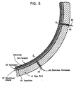
- Fig. 5 is a cross-sectional view of the pipe section of Fig. 1 showing how electrodes are mounted to the wall of the pipe section for non-intrusively generating and sensing displacement current.
- Fig. 6 schematically illustrates the electrodes for generating and sensing displacement currents and the relationship of these electrodes to the pipe wall of the pipe interior.
- Fig. 7 shows a model circuit which models the electrode and pipe system and sensing circuity for determining the magnitude and phase of displacement currents.
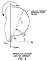
- Fig. 8 is a plot of the magnitude and phase of displacement currents under various circumstances.
- Fig. 9 shows sensing circuitry for determining the magnitude and phase of displacement currents in greater detail.
- Fig. 10 shows circuitry for transmitting parameters such as magnitude and phase of a displacement current to a main computer.
- Fig. 11 shows the algorithm used by the main computer to output information about the state of a multiphase fluid in a pipe.
- Fig. 1 there is shown a cutaway view of a section of pipe 10 in which there flows a multiphase fluid.
- the pipe section is near an oil well head and the multiphase fluid is an oil/gas/water mixture.
- the direction of flow of the multiphase fluid is indicated by the arrow 12.
- the pipe section 10 has a first flange 14 for connection to a downstream pipe section and a second flange 16 for connection to an upstream section.
- the overall length of the pipe section 10 is from 10 inches to 48 inches dependent on pipe diameter.
- the diameter of the pipe section 10 typically is from 2 inches to 60 inches.
- transducers/sensors for performing four types of non-intrusive measurements to obtain parameters which can yield information about the state of the multiphase fluid flowing inside the pipe section.
- the four types of measurements are transit-time, reflexor, bubble detection, and displacement current.
- the transducers/sensors used to perform the measurements are described in greater detail below.
- the pipe section 10 is surrounded by a box-like housing 20.
- the housing 20 is for example 36 inches long, 12 inches wide, and 8 inches high.
- the housing 20 includes a cover 22.
- Mounted on the cover 22 is an optional electronics housing and junction box 24.
- the circuitry in the electronics housing and junction box 24 provides signals to and receives signals from the transducers/sensors coupled to the pipe wall.
- the housing 20 and cover 22 are important because they protect the transducers/sensors from a very harsh external environment such as that found at an oil well head thousands of feet below sea level.
- transducers/sensors are now considered in greater detail. There is a pair of sonic transducers/sensors for obtaining transit-time information. This pair of sonic transducers/sensors is labeled 32, 34.
- the sonic transducers/sensors 32, 34 are contained in a separate housing 36 inside of housing 20.
- Transit-time path 1 is the path between transducer/sensor 32 and transducer/sensor 34.
- a second pair of sonic transducers/sensors may be provided in another separate housing within the housing 20.
- the second pair of transducers/sensors is separated by a second transit-time path.
- Fig. 2 is a longitudinal cross section of a portion of the pipe section 10.
- the transducer/sensor 32 and the transducer/sensor 34 are mounted on the wall of the pipe section 10.
- a pulse of sonic energy 50 is introduced into the fluid in the pipe section 10 by the transducer/sensor 32.
- the pulse of sonic energy propagates generally codirectionally with the fluid flow F.
- the pulse of sonic energy is detected by the transducer/sensor 34.
- the time of propagation of the pulse along transit-time path 1 is t 1 .
- a similar time t 2 is obtained by transmitting a sonic pulse along transit-time path 1 between transducer/sensor 34 and transducer/sensor 32.
- This second pulse propagates generally counter-directionally to the fluid flow F.
- a sonic transducer 52 and sensor 54 for implementing the reflexor technique.
- the transducer 52 and sensor 54 are located within the housing 56 which is contained within the housing 20.
- Fig. 3 shows the operation of the reflexor technique in greater detail.
- Fig. 3 shows a longitudinal cross section of a portion of the pipe section 10.
- the transducer 52 and the sensor 54 are mounted on the wall of the pipe 10.
- the transducer 52 transmits a pulse of sonic energy of a particular frequency into the fluid in the pipe section 10.
- the sonic energy is reflected from particles 58 in the fluid and sensed by the sensor 54.
- the reflected sonic energy is at a different frequency than the initial sonic energy.
- a bubble detector Also coupled to the wall of the pipe section 10 is a bubble detector.
- the bubble detector is not shown in Fig. 1, but can be seen in Fig. 4.
- Fig. 4 is a cross section of the pipe section 10 of Fig. 1 taken along view B.
- Fig. 4 shows the transducer/sensor 32 for transit-time path 1, and the transducer 54 for reflexor detection as well as a bubble detector 60.
- the pipe section 10 includes electrodes for generating and sensing a displacement current which flows in a field created by the electrodes.
- This displacement current will be proportional to the dielectric constant of the fluid in the pipe or to its conductivity or to some combination of each.
- Two sets of electrodes 70, 80 are shown in Fig. 1.
- the set 70 comprises the electrodes E 1 , A 1 .
- the set 80 comprises the electrodes E 2 and A 2 .
- Each electrode is approximately 12 inches long and 1 inch wide.
- the circumferential spacing between adjacent electrodes in the same set is 1/8 inch.
- the longitidinal spacing between corresponding electrodes of the two sets is 1/4 inch.
- Each set 70, 80 may include additional electrodes located on the pipe section circumference.
- the electrodes are separated from the fluid in the pipe by a physical barrier such as a layer of ceramic or other low conductivity or dielectric material.
- FIG. 5 A cross-section of the pipe section 10 taken along A-A is shown in Fig. 5.
- the inner wall of the pipe section 10 is covered with an insulator 61.
- This layer is made from non-conductive material and has a thickness of 1/16 - 1/8 inch.
- the next layer is an electrical shield layer 62 made of steel and having a thickness of 0.01 inches.
- the next layer is an insulator layer 63 made of teflon, for example, and having a thickness of 0.020 inches.
- the electrodes E 1 and A 1 are formed from steel and have a thickness of 0.01 inches.
- the electrodes, as well as portions of the insulator 63 not covered by the electrodes, are covered with a ceramic layer 64 and having a thickness of up to 1/8 inch at the locations which are over the electrodes.
- the pipe wall as well as the layers 61, 62, 63 have openings 66, 67, through which electrode terminals 68, 69, are connected to the electrodes E 1 , A 1 .
- Fig. 6 illustrates the generation and detection of displacement currents using the electrodes.
- Fig. 6 shows the electrodes E 1 , A 1 of Fig. 1 and an additional set of electrodes B 1 not shown in Fig. 1. These electrodes are coupled to the wall of the pipe section 10 in the manner shown in Fig. 5.
- the electrodes E 1 are driven by a variable voltage source 101 at a frequency of 0.1 to 1.0 MHz, for example to generate a displacement current in the interior of the pipe.
- a displacement current which flows along the electric field lines F 1 is detected at the electrode A 1 .
- a displacement current which flows along the electric field lines F 2 is detected at the electrodes B 1 .
- the A sensor circuit measures the magnitude and phase of the displacement current detected at the electrode A 1 .
- the B sensor circuit measures the phase and magnitude of the displacement current detected at the electrode B 1 .
- the circuit path from the electrode E 1 to the electrode A 1 may be modeled by three elements connected in series. There is a capacitive element E c which models the electrode E 1 and the ceramic film 64. There is a capacitive/resistive element A s which models the fluid in the pipe. There is also a capacitive element A c which models the ceramic film 64 and the electrode A 1 .
- a similar set of three elements connected in series can be used to model the circuit path from the electrode E 1 to other electrodes such as the electrodes B 1 of Fig. 6 and the circuit path between the electrodes E 2 and A 2 of Fig. 1.
- Fig. 7 is a circuit diagram which includes a model circuit 90 of the pipe and electrode system of Fig. 6.
- the model circuit 90 includes the capacitive element E c , the capacitive/resistive element A s , and the capacitive element A c .
- the model circuit 90 is driven by the AC voltage source 101.
- Fig. 8 is a plot of a displacement current which flows between the driving electrode E 1 and sensing electrode A 1 in the case of an oil/gas/ water mixture with different relative amounts of each phase.
- the net displacement current which flows between the electrodes E 1 and A 1 depends on the impedances of the circuit elements E c , A s , A c .
- the impedance of A s is lower than the impedance of E c and A c . This results in the displacement current I oil or I gas of Fig. 8.
- the pipe is filled with a conducting fluid such as salt water
- a conducting fluid such as salt water
- the field within the pipe interior is shorted out, so that the net current I saltwater is limited only by the impedance of E c and/or A c so that the largest current flows.
- the impedance element A s has a resistive component resulting in the current I p of Fig. 8.
- the current I p has a phase angle ⁇ relative to the driving voltage V in .
- the magnitude and/or phase of the displacement current will vary. In general, the current resulting from a partially conducting fluid will lie along the locus shown in Fig. 8.
- Fig. 7 shows the model circuit 90 and voltage source 101 as forming one arm 92 of a capacitance bridge 93.
- the other arm 102 of the capacitance bridge is formed by the variable voltage source 103 (which may be implemented by an operational amplifier) and a capacitance C m .
- a variable capacitance C v may be provided for balancing adjustments.
- the bridge may be designed to be in balance when the fluid in the pipe is purely dielectric, e.g., having the dielectric constant of pure oil. Then if some gas is in the pipe, the bridge could become unbalanced in the direction of reduced dielectric constant.
- the bridge would be unbalanced in the direction of increased dielectric constant.
- the phase angle of the current, relative to the driving voltage V in indicates either gas or water, even if the magnitude of the current in both cases happens to be identical.
- the bridge 93 is unbalanced, the current at the node 105 is converted to a voltage by the current-to-voltage converter 107 which may be implemented by an op-amp.
- the bridge 93 of Fig. 7 forms part of the sensing circuitry of Fig. 6 (e.g., the A sensor circuit of Fig. 6).
- the voltage output of the current-to-voltage converter 107 is then transmitted to a phase detector 109 which detects the phase of the signal relative to the input voltage V in and an envelope detector 111 which detects the magnitude of the signal. These signals are then digitized and transmitted to a main computer in a manner to be discussed below.
- a similar circuit including capacitance bridge, phase detector, and envelope detector is provided for other electrodes in set 70 of Fig. 1 (e.g., electrode B 1 ) and for the electrodes of set 80 of Fig. 1.
- Fig. 9 includes the bridge 93, the model 90 of the pipe and electrode system, the driving voltage source 101 and the balancing arm 102, which comprises the capacitor C m and the variable voltage source 103.
- the variable voltage source 103 is formed from an op-amp (operational amplifier) T 1 and variable resistor R 1 .
- the current-to-voltage converter 107 is formed from op-amp T 2 , variable resistor R 2 , resistor R 3 and capacitor C 1 .
- the envelope detector 111 comprises the op-amps T 3 , T 4 , T 5 , T 6 , the resistors R 3 , R 4 , R 5 , R 6 , R 7 , R 8 , R 9 , R 10 , R 11 , the diodes D 1 , D 2 , D 3 , and the capacitors C 2 , and C 3 .
- the output of the envelope detector 111 at the output 120 is the magnitude or envelope of the displacement current.
- the phase detector 109 comprises the comparitors T 7 and T 8 , the XOR gate G 1 , the comparator T 9 , the capacitor C 4 , the resistor R 12 , the op-amp T 10 , the resistors R 13 , R 14 , R 15 , and R 16 , and the capacitor C 5 .
- the output of the phase detector 109 at the output 122 is the phase of the displacement current relative to V in .
- Fig. 10 shows a circuit for accomplishing this.
- the parameters detected by the various sensors non-intrusively coupled to the pipe section 10 of Fig. 1 are input to an A/D converter 300 and converted to digital form.
- the parameters may include magnitudes and phases of displacement currents flowing between particular electrodes, including electrodes from one set having a first location along the pipe section, and electrodes from one or more additional sets located at other locations along the pipe.
- the parameters may also include parameters obtained from transit-time sensors, reflexor sensors, or bubble detector sensors. The parameters may be different depending on the application. In some applications, only parameters obtained from displacement currents may be utilized and the transit-time, reflexor, and bubble detection may be omitted.
- the parameter signals are converted to digital form by A/D converter 300.
- the digitized parameter signals are then multiplexed using MUX 310.
- the multiplexed signal is then transmitted remotely by transmitter 320.
- the transmitted parameters are received by the receiver 330 and transmitted to the computer 340.
- the computer 340 uses the received parameters to provide information about the state of the multiphase fluid inside the pipe section.
- the computer 340 also uses a database stored in the memory 350.
- the database is determined empirically by measuring parameter values for known conditions or states in the pipe.
- the computer does not use the received parameters to evaluate equations of state.
- An alternative approach that might be useful in particular circumstances might be for the computer to use the received parameters to evaluate equations of state.
- the algorithm used by the computer 340 to determine information about the state of the multiphase fluid inside the pipe section is illustrated in the flow chart of Fig. 11.
- the computer receives the parameters (step 410).
- the computer correlates the received parameters with the database, to find the database entry which is closest to the received parameters (step 420).
- This database entry contains information about the state of the multiphase fluid in the pipe section.
- the computer then outputs this information (step 430).
- the database is stored in a memory associated with the computer.
- One significant feature of the invention is that it can be used to generate time based information such as flow rate information. This may be accomplished using the two sets of electrodes 70, 80 of Fig. 1.
- the first set of electrodes 70 may generate a certain set of parameters at a first time. These parameters can be used by the computer 340 to identify a certain state of the multiphase fluid at the location of the first set of electrodes at the first time. The fluid will then flow down the pipe section 10 to the location of the second set of electrodes 80.
- These electrodes will generate at a second time a set of parameters similar to that generated by the first set of electrodes at the first time. This will indicate the time it takes the fluid to travel the known distance between the sets of electrodes by correlating these parameters.
Landscapes
- Physics & Mathematics (AREA)
- Fluid Mechanics (AREA)
- General Physics & Mathematics (AREA)
- Investigating Or Analyzing Materials By The Use Of Electric Means (AREA)
- Measuring Volume Flow (AREA)
Applications Claiming Priority (2)
| Application Number | Priority Date | Filing Date | Title |
|---|---|---|---|
| US3096798A | 1998-02-26 | 1998-02-26 | |
| US30967 | 2008-02-24 |
Publications (1)
| Publication Number | Publication Date |
|---|---|
| EP0947810A1 true EP0947810A1 (fr) | 1999-10-06 |
Family
ID=29248046
Family Applications (1)
| Application Number | Title | Priority Date | Filing Date |
|---|---|---|---|
| EP99301389A Withdrawn EP0947810A1 (fr) | 1998-02-26 | 1999-02-25 | Débitmètre multiphasique |
Country Status (1)
| Country | Link |
|---|---|
| EP (1) | EP0947810A1 (fr) |
Cited By (3)
| Publication number | Priority date | Publication date | Assignee | Title |
|---|---|---|---|---|
| WO2001065212A1 (fr) * | 2000-03-03 | 2001-09-07 | Shell Internationale Research Maatschappij B.V. | Compteur de capacite |
| EP1963819A2 (fr) * | 2005-12-22 | 2008-09-03 | Honeywell International, Inc. | Systeme d'analyseur portatif d'echantillons |
| CN104198813B (zh) * | 2014-05-09 | 2017-06-27 | 杭州电子科技大学 | 一种正交相关法测量超声换能器阻抗角的装置及方法 |
Citations (5)
| Publication number | Priority date | Publication date | Assignee | Title |
|---|---|---|---|---|
| EP0280814A2 (fr) * | 1987-01-05 | 1988-09-07 | Texaco Development Corporation | Appareil et procédé pour la mesure d'une caractéristique fluidique d'un courant de pétrole |
| US5396806A (en) * | 1993-11-12 | 1995-03-14 | Auburn International, Inc. | On-line mass flow measurement in flowing two component systems |
| EP0691527A1 (fr) * | 1994-07-05 | 1996-01-10 | Institut Français du Pétrole | Dispositif et méthode de mesure de profil de vitesse dans un fluide polyphasique |
| EP0691536A1 (fr) * | 1994-07-08 | 1996-01-10 | Institut Francais Du Petrole | Débitmètre polyphasique |
| WO1997039314A1 (fr) * | 1996-04-16 | 1997-10-23 | Mobil Oil Corporation | Procede de controle d'un ecoulement de fluide a trois phases dans des conduits tubulaires |
-
1999
- 1999-02-25 EP EP99301389A patent/EP0947810A1/fr not_active Withdrawn
Patent Citations (5)
| Publication number | Priority date | Publication date | Assignee | Title |
|---|---|---|---|---|
| EP0280814A2 (fr) * | 1987-01-05 | 1988-09-07 | Texaco Development Corporation | Appareil et procédé pour la mesure d'une caractéristique fluidique d'un courant de pétrole |
| US5396806A (en) * | 1993-11-12 | 1995-03-14 | Auburn International, Inc. | On-line mass flow measurement in flowing two component systems |
| EP0691527A1 (fr) * | 1994-07-05 | 1996-01-10 | Institut Français du Pétrole | Dispositif et méthode de mesure de profil de vitesse dans un fluide polyphasique |
| EP0691536A1 (fr) * | 1994-07-08 | 1996-01-10 | Institut Francais Du Petrole | Débitmètre polyphasique |
| WO1997039314A1 (fr) * | 1996-04-16 | 1997-10-23 | Mobil Oil Corporation | Procede de controle d'un ecoulement de fluide a trois phases dans des conduits tubulaires |
Cited By (4)
| Publication number | Priority date | Publication date | Assignee | Title |
|---|---|---|---|---|
| WO2001065212A1 (fr) * | 2000-03-03 | 2001-09-07 | Shell Internationale Research Maatschappij B.V. | Compteur de capacite |
| US6915703B2 (en) | 2000-03-03 | 2005-07-12 | Shell Oil Company | Capacitance meter |
| EP1963819A2 (fr) * | 2005-12-22 | 2008-09-03 | Honeywell International, Inc. | Systeme d'analyseur portatif d'echantillons |
| CN104198813B (zh) * | 2014-05-09 | 2017-06-27 | 杭州电子科技大学 | 一种正交相关法测量超声换能器阻抗角的装置及方法 |
Similar Documents
| Publication | Publication Date | Title |
|---|---|---|
| Shi et al. | Flow rate measurement of oil-gas-water wavy flow through a combined electrical and ultrasonic sensor | |
| JP4800543B2 (ja) | 多相液体/気体混合物の流量及び濃度を同時に測定する方法及び装置 | |
| US10746582B2 (en) | Sensing annular flow in a wellbore | |
| US6650280B2 (en) | Measurement system and method | |
| RU2183012C2 (ru) | Способ измерения многофазного потока и устройство для его осуществления | |
| US10168198B2 (en) | Bulk acoustic wave (BAW) sensors for liquid level measurements | |
| US9714854B2 (en) | Multiphase in situ flow sensing with ultrasonic tomography and vortex shedding | |
| US8820147B2 (en) | Multiphase fluid characterization system | |
| US6467358B1 (en) | Method of measuring flow rates of respective fluids constituting multiphase fluid and flow meter for multiphase flow utilizing same | |
| US4980642A (en) | Detection of influx of fluids invading a borehole | |
| US6598473B2 (en) | Quantity gauging | |
| WO2017222874A1 (fr) | Détection de flux multiphase in situ par tomographie ultrasonore et décollement de tourbillons | |
| NO339488B1 (no) | Anordning og fremgangsmåte for måling av en parameter i en multifasestrømning | |
| RU2002126261A (ru) | Фарадметр | |
| CN108955787B (zh) | 测量设备 | |
| JP2004514876A (ja) | 流体レベル測定装置および方法 | |
| CN111289579A (zh) | 一种基于陆面气液分离集成传感器及持水率矫正方法 | |
| US20150308869A1 (en) | Flow data acquisition and telemetry processing systems | |
| WO2006083170A1 (fr) | Appareil de mesure d’ecoulement | |
| JP2004093565A (ja) | 充填レベル測定機器 | |
| EP0385856A2 (fr) | Procédé et appareil pour mesurer le diamètre de puits à l'aide d'ondes électromagnétiques | |
| EP0947810A1 (fr) | Débitmètre multiphasique | |
| Meribout et al. | Interface layers detection in oil field tanks: A critical review | |
| JP2000249673A (ja) | 多相流体の成分率測定方法及びそれを利用した成分率計 | |
| RU66029U1 (ru) | Комплексное устройство измерения расхода, плотности и вязкости нефтепродуктов |
Legal Events
| Date | Code | Title | Description |
|---|---|---|---|
| PUAI | Public reference made under article 153(3) epc to a published international application that has entered the european phase |
Free format text: ORIGINAL CODE: 0009012 |
|
| AK | Designated contracting states |
Kind code of ref document: A1 Designated state(s): AT BE CH CY DE DK ES FI FR GB GR IE IT LI LU MC NL PT SE |
|
| AX | Request for extension of the european patent |
Free format text: AL;LT;LV;MK;RO;SI |
|
| AKX | Designation fees paid | ||
| REG | Reference to a national code |
Ref country code: DE Ref legal event code: 8566 |
|
| STAA | Information on the status of an ep patent application or granted ep patent |
Free format text: STATUS: THE APPLICATION IS DEEMED TO BE WITHDRAWN |
|
| 18D | Application deemed to be withdrawn |
Effective date: 20000407 |