EP0947818A2 - Simulationsvorrichtung für Kraftfahrzeugunfälle und Verfahren zum Simulieren von Kraftfahrzeugunfällen - Google Patents
Simulationsvorrichtung für Kraftfahrzeugunfälle und Verfahren zum Simulieren von Kraftfahrzeugunfällen Download PDFInfo
- Publication number
- EP0947818A2 EP0947818A2 EP99101648A EP99101648A EP0947818A2 EP 0947818 A2 EP0947818 A2 EP 0947818A2 EP 99101648 A EP99101648 A EP 99101648A EP 99101648 A EP99101648 A EP 99101648A EP 0947818 A2 EP0947818 A2 EP 0947818A2
- Authority
- EP
- European Patent Office
- Prior art keywords
- motor vehicle
- speed
- sensors
- roadway
- simulation device
- Prior art date
- Legal status (The legal status is an assumption and is not a legal conclusion. Google has not performed a legal analysis and makes no representation as to the accuracy of the status listed.)
- Granted
Links
- 238000000034 method Methods 0.000 title claims description 18
- 238000004088 simulation Methods 0.000 claims abstract description 19
- 206010039203 Road traffic accident Diseases 0.000 claims abstract description 6
- 238000011156 evaluation Methods 0.000 claims description 14
- 230000004888 barrier function Effects 0.000 claims description 4
- 238000004364 calculation method Methods 0.000 claims description 4
- 238000002604 ultrasonography Methods 0.000 claims description 4
- 230000005540 biological transmission Effects 0.000 claims description 2
- 238000001514 detection method Methods 0.000 description 7
- 238000002360 preparation method Methods 0.000 description 6
- 230000001419 dependent effect Effects 0.000 description 3
- 238000002485 combustion reaction Methods 0.000 description 1
- 230000000694 effects Effects 0.000 description 1
- 238000012423 maintenance Methods 0.000 description 1
- 230000001105 regulatory effect Effects 0.000 description 1
Images
Classifications
-
- G—PHYSICS
- G01—MEASURING; TESTING
- G01M—TESTING STATIC OR DYNAMIC BALANCE OF MACHINES OR STRUCTURES; TESTING OF STRUCTURES OR APPARATUS, NOT OTHERWISE PROVIDED FOR
- G01M17/00—Testing of vehicles
- G01M17/007—Wheeled or endless-tracked vehicles
- G01M17/0078—Shock-testing of vehicles
Definitions
- the invention relates to a simulation device for motor vehicle accidents with a Roadway on which at least one motor vehicle collides with a point of collision Obstacle or another motor vehicle is movable, according to the preamble of claim 1.
- the invention further relates to a method for simulating motor vehicle accidents, wherein at least one motor vehicle on a collision point on a roadway is moved with an obstacle or another motor vehicle, according to the preamble of claim 10.
- DE 40 06 433 A1 and EP 0 445 671 A1 describe an apparatus and a method known for checking effects of a motor vehicle accident, in which at least a motor vehicle is guided to a previously defined collision point.
- the Motor vehicle is guided remotely according to specified movement parameters, a memory with target values for these movement parameters is provided.
- a The on-board controller is connected to sensors in the motor vehicle and thereby takes actual values the movement parameters.
- the vehicle or vehicles are connected to a guide cable led on a predetermined path. This guide cable is on or in a lane arranged. Corresponding trigger marks on the guide cable result in synchronization of several vehicles that point to a common collision point drive in and arrive there at the same time.
- this system has the disadvantage that the components for recording actual values for vehicle speed and Vehicle position are complicated and expensive because they are arranged in the vehicle and must be trained to be crash-proof.
- DE-OS 26 48 126 describes an arrangement for speed control of trackless vehicles using a guide cable. This is from a sound frequency AC flowed through. This alternating current creates a magnetic field, which in turn in at least two coils in the motor vehicle from the lateral deviation of the Vehicle-dependent voltages generated for the guide cable. From these tensions corresponding control signals for a steering controller are derived.
- This guide cable is arranged with an additional cable, which is of a current flow through a selectable measuring frequency compared to the current in the guide cable. A crossover is provided for the voltage induced with the measuring frequency, which in an evaluation circuit depending on the distance between the cables controls the vehicle speed. Also with this system are essential Parts of the actual value detection for speed and position of the motor vehicle in this self-arranged, which corresponds to a preparation effort for a simulation run elevated.
- a device for speed control is trackless Vehicles known by brands arranged along the road, each of which emits a signal as soon as the vehicle drives past. These signals are from a corresponding Equipment recorded in the vehicle itself and evaluated accordingly. Again there are the appropriate facilities for speed and Position detection in the vehicle itself.
- DE-AS 21 52 752 teaches alongside the roadway emitting frequency signals Arrange setpoint device for a vehicle speed, which is from a Vehicle itself arranged receiver can be read out. An actuator for the vehicle drive controls a vehicle speed in accordance with these frequency signals. The respective actual values to be compared with the target signals for the Speed is determined in the vehicle itself with all of these in the aforementioned Wise disadvantages.
- the present invention is therefore based on the object of a simulation device of the above type and a method of the above. kind of providing the disadvantages mentioned above being overcome.
- stationary sensors are arranged along the road, each one scan predetermined area of the lane area and a speed and detect a position of the motor vehicle on the road.
- a complete and complete scanning of the road area can be achieved that the sensors are arranged such that their respective scanning areas at least partially overlap.
- the sensors transmit to detect speed and position of the motor vehicle a signal and take appropriate Reflections and / or interruptions of this signal from one on the road located motor vehicle on.
- an echo run time of the reflections a distance of the motor vehicle from the sensor and thus its location and from a Doppler shift of the reflected signal, possibly a speed of the vehicle be determined.
- the signals emitted by the sensors are expediently ultrasound and / or electromagnetic waves in the visible range and / or infrared range and / or radar range.
- the sensors have at least one light barrier.
- At least one sensor is expediently a laser scanner or a video camera.
- a pressure sensor for example, one is corresponding by driving over one in a pressure generated by gas-filled device.
- all sensors have an evaluation unit connected, which receives scanning signals emitted by the sensors and for the calculation of actual values of the speed and the position of the motor vehicle evaluates on the road.
- the evaluation unit expediently has one Calculation unit, which, for example, from the actual values below Comparison with control signals corresponding control signals for control devices in the motor vehicle calculated.
- the evaluation unit also has a transmission device, in particular a radio transmitter or infrared transmitter, which transmits the control signals to a corresponding receiver in the motor vehicle.
- the speed and / or position of the Motor vehicle from at least one sensor using a signal echo method, in particular by means of ultrasound and / or electromagnetic waves in the visible range, determined in the infrared range and / or in the radar range.
- a particularly simple and reliable method can be achieved in that the Speed and / or position of the motor vehicle by means of at least one sensor a signal interruption method, for example by means of a light barrier, is determined.
- the speed and / or Position of the motor vehicle by at least one sensor in the form of a laser scanner certainly.
- scanning signals emitted by the sensors are emitted by a Evaluation unit included and for determining actual values for speed and location of the motor vehicle evaluated.
- control signals For a precisely predetermined guidance of the motor vehicle on the road to The collision point is made up of the actual values and a comparison with target values of a control unit corresponding control signals for control devices in the motor vehicle calculated. It is particularly expedient here for the control signals to be wireless to transmit the motor vehicle.
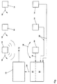
- a motor vehicle 10 is along a roadway 12 to a collision point, not shown movable there.
- Sensors 14 are arranged on both sides of the road with a respective detection area 16. When the vehicle 10 moves along the Roadway 12 occurs one after the other in the respective detection areas 16 of the sensors 14 a.
- Each sensor is connected via a line 18 to a computer-controlled pre-evaluation unit 20 connected.
- the actual values are obtained via lines 18 received sensor scanning signals determined and via a transmitter 22 and Radio link 24 transmitted to vehicle 10.
- This radio link is preferred as a carrier electromagnetic waves, for example in the infrared (IR) or frequency range Ultra short wave (VHF).
- the vehicle 10 is intended to collide with an obstacle or another Vehicle collide in a predetermined manner and is therefore also called a crash vehicle 10 designated.
- the position and the speed of appropriate control devices of the vehicle 10 regulated.
- target values are in the vehicle, for example saved for location and speed. These have to be used to calculate Control signals for corresponding actuators with instantaneous actual values for position and Speed can be compared.
- These actual values determine the stationary ones outside the vehicle 10 Sensors 14, for example, using an echo evaluation method.
- send the Sensors emit a signal, such as a radar wave, and take an echo signal on.
- the actual values determined in this way become the control devices located in the vehicle 10 for position (actuator for steering) and speed (e.g. actuator for Throttle valve of an internal combustion engine) supplied via the radio link 24.
- control signals can also be determined directly in the pre-evaluation unit 20 are so that the control signals for the respective actuators directly via the radio link 24 be transmitted.
- the sensors do not have to be reinstalled for every simulation run, but instead are permanently arranged so that they are available at all times and without reinstallation. Since they are stationary and immovable, this is not necessary with conventional systems required high maintenance and preparation effort for these systems for position / speed detection.
Landscapes
- Physics & Mathematics (AREA)
- General Physics & Mathematics (AREA)
- Traffic Control Systems (AREA)
- Electric Propulsion And Braking For Vehicles (AREA)
Abstract
Description
- 10
- Kraftfahrzeug
- 12
- Fahrbahn
- 14
- Sensoren
- 16
- Erfassungsbereich
- 18
- Leitung
- 20
- Vorauswerteinheit
- 22
- Sender
- 24
- Funkstrecke
Claims (16)
- Simulationsvorrichtung für Kraftfahrzeugunfälle mit einer Fahrbahn (12), auf der wenigstens ein Kraftfahrzeug (10) auf einen Kollisionspunkt mit einem Hindernis oder einem anderen Kraftfahrzeug zubewegbar ist,
dadurch gekennzeichnet, daß
entlang der Fahrbahn (12) stationär Sensoren (14) angeordnet sind, welche jeweils einen vorbestimmten Bereich (16) des Fahrbahnbereiches abtasten sowie eine Geschwindigkeit und eine Lage des Kraftfahrzeuges (10) auf der Fahrbahn (12) erfassen. - Simulationsvorrichtung nach Anspruch 1,
dadurch gekennzeichnet, daß
die Sensoren (14) derart angeordnet sind, daß sich deren jeweilige Abtastbereiche (16) wenigstens teilweise überschneiden. - Simulationsvorrichtung nach Anspruch 1 oder 2,
dadurch gekennzeichnet, daß
die Sensoren (14) zum Erfassen von Geschwindigkeit und Lage des Kraftfahrzeuges (10) ein Signal aussenden und entsprechende Reflektionen und/oder Unterbrechungen dieses Signals von einem auf der Fahrbahn (12) befindlichen Kraftfahrzeug (10) aufnehmen. - Simulationsvorrichtung nach einem der vorhergehenden Ansprüche,
dadurch gekennzeichnet, daß
das Signal Ultraschall und/oder elektromagnetische Wellen im sichtbaren Bereich und/oder Infrarotbereich und/oder Radarbereich sind. - Simulationsvorrichtung nach einem der vorhergehenden Ansprüche,
dadurch gekennzeichnet, daß
die Sensoren (14) wenigstens eine Lichtschranke aufweisen. - Simulationsvorrichtung nach einem der vorhergehenden Ansprüche,
dadurch gekennzeichnet, daß
wenigstens ein Sensor (14) ein Laserscanner, ein Drucksensor oder eine Videokamera ist. - Simulationsvorrichtung nach einem der vorhergehenden Ansprüche,
dadurch gekennzeichnet, daß
alle Sensoren (14) mit einer Auswerteeinheit (20) verbunden sind, welche von den Sensoren (14) abgegebene Abtastsignale aufnimmt und zur Berechnung von Ist-Werten der Geschwindigkeit und der Lage des Kraftfahrzeuges (10) auf der Fahrbahn (10) auswertet. - Simulationsvorrichtung nach Anspruch 7,
dadurch gekennzeichnet, daß
die Auswerteeinheit (20) eine Berechnungseinheit aufweist, welche aus den Ist-Werten unter Vergleich mit Soll-Werten entsprechende Regelsignale für Regeleinrichtungen im Kraftfahrzeug (10) berechnet. - Simulationsvorrichtung nach Anspruch 7 oder 8,
dadurch gekennzeichnet, daß
die Auswerteeinheit (20) ferner eine Übertragungseinrichtung (22,24), insbesondere einen Funksender oder Infrarotsender, aufweist, welcher die Regelsignale an einen entsprechenden Empfänger im Kraftfahrzeug (10) überträgt. - Verfahren zum Simulieren von Kraftfahrzeugunfällen, wobei auf einer Fahrbahn wenigstens ein Kraftfahrzeug auf einen Kollisionspunkt mit einem Hindernis oder einem anderen Kraftfahrzeug zubewegt wird,
dadurch gekennzeichnet, daß
während der Bewegung des Kraftfahrzeugs auf der Fahrbahn Ist-Werte von dessen Geschwindigkeit und Lage von benachbart zur Fahrbahn liegenden Positionen aus bestimmt werden. - Verfahren nach Anspruch 10,
dadurch gekennzeichnet, daß
die Geschwindigkeit und/oder Lage des Kraftfahrzeugs von wenigstens einem Sensor mittels eines Signalechoverfahrens, insbesondere mittels Ultraschall und/oder elektromagnetischen Wellen im sichtbaren Bereich, im Infrarotbereich und/oder im Radarbereich bestimmt wird. - Verfahren nach Anspruch 10 oder 11,
dadurch gekennzeichnet, daß
die Geschwindigkeit und/oder Lage des Kraftfahrzeugs von wenigstens einem Sensor mittels eines Signalunterbrechungsverfahrens, beispielsweise mittels einer Lichtschranke, bestimmt wird. - Verfahren nach einem der Ansprüche 10 bis 12,
dadurch gekennzeichnet, daß
die Geschwindigkeit und/oder Lage des Kraftfahrzeugs von wenigstens einem Sensor in Form eines Laserscanners bestimmt wird. - Verfahren nach einem der Ansprüche 10 bis 13,
dadurch gekennzeichnet, daß
von den Sensoren abgegebene Abtastsignale von einer Auswerteeinheit aufgenommen und zum Bestimmen von Ist-Werten für Geschwindigkeit und Lage des Kraftfahrzeuges ausgewertet werden. - Verfahren nach einem der Ansprüche 10 bis 12,
dadurch gekennzeichnet, daß
aus den Ist-Werten und einem Vergleich mit Soll-Werten von einer Berechnungseinheit entsprechende Regelsignale für Regeleinrichtungen im Kraftfahrzeug berechnet werden. - Verfahren nach Anspruch 15,
dadurch gekennzeichnet, daß
die Regelsignale drahtlos an das Kraftfahrzeug übertragen werden.
Applications Claiming Priority (2)
| Application Number | Priority Date | Filing Date | Title |
|---|---|---|---|
| DE19814844 | 1998-04-02 | ||
| DE1998114844 DE19814844B4 (de) | 1998-04-02 | 1998-04-02 | Simulationsvorrichtung für Kraftfahrzeugunfälle und Verfahren zum Simulieren von Kraftfahrzeugunfällen |
Publications (3)
| Publication Number | Publication Date |
|---|---|
| EP0947818A2 true EP0947818A2 (de) | 1999-10-06 |
| EP0947818A3 EP0947818A3 (de) | 2000-01-12 |
| EP0947818B1 EP0947818B1 (de) | 2008-06-18 |
Family
ID=7863402
Family Applications (1)
| Application Number | Title | Priority Date | Filing Date |
|---|---|---|---|
| EP19990101648 Expired - Lifetime EP0947818B1 (de) | 1998-04-02 | 1999-02-05 | Simulationsvorrichtung für Kraftfahrzeugunfälle und Verfahren zum Simulieren von Kraftfahrzeugunfällen |
Country Status (2)
| Country | Link |
|---|---|
| EP (1) | EP0947818B1 (de) |
| DE (2) | DE19814844B4 (de) |
Cited By (1)
| Publication number | Priority date | Publication date | Assignee | Title |
|---|---|---|---|---|
| WO2005071384A1 (de) * | 2004-01-21 | 2005-08-04 | TÜV SÜD Automotive GmbH | Verfahren zum führen eines fahrzeugs längs einer vorbestimmten bahn sowie fahrzeug und system zum durchführen von crash-versuchen |
Families Citing this family (3)
| Publication number | Priority date | Publication date | Assignee | Title |
|---|---|---|---|---|
| DE102004056380B4 (de) * | 2004-11-23 | 2010-07-08 | TÜV Kraftfahrt GmbH - TÜV Rheinland Group | Messvorrichtung und Verfahren zur Messung eines freifliegenden Körpers |
| DE102008030612B3 (de) * | 2008-06-27 | 2009-12-31 | Audi Ag | Vorrichtung und Verfahren zum Herbeiführen von kollisionsnahen und kollisionsfreien Situationen zwischen einem Testfahrzeug und einem Kollisionsobjekt und Einrichtung zur Funktionsprüfung eines Fahrerassistenzsystems |
| DE102008051233A1 (de) | 2008-10-10 | 2009-05-20 | Daimler Ag | Vorrichtung und Verfahren zum Testen mindestens einer Funktion mindestens eines Fahrerassistenzsystems |
Family Cites Families (7)
| Publication number | Priority date | Publication date | Assignee | Title |
|---|---|---|---|---|
| NL135492B (de) * | 1961-07-25 | |||
| US3681597A (en) * | 1970-06-01 | 1972-08-01 | Alden Self Transit Syst | Transportation system |
| DE3022356A1 (de) * | 1980-06-14 | 1982-01-14 | Reinhold 7996 Meckenbeuren Fischer | Geschwindigkeitsmesssystem, insbesondere fuer strassenfahrzeuge |
| DE3830598A1 (de) * | 1988-09-08 | 1990-03-22 | Messerschmitt Boelkow Blohm | Verfahren zum messen des verkehrsflusses auf strassen |
| DE4006433C2 (de) * | 1990-03-01 | 2000-01-20 | Inst Fahrzeugtechnik Gmbh Unte | Verfahren und Vorrichtung zum Überprüfen von Wirkungen eines Kraftfahrzeug-Unfalls |
| DE19529801C1 (de) * | 1995-08-14 | 1996-07-18 | Ford Werke Ag | Vorrichtung zur Durchführung eines Crashtests bei einem Fahrzeug |
| IT1286684B1 (it) * | 1996-07-26 | 1998-07-15 | Paolo Sodi | Dispositivo e metodo per il rilevamento di infrazioni stradali con sistemi di puntamento dinamico |
-
1998
- 1998-04-02 DE DE1998114844 patent/DE19814844B4/de not_active Expired - Fee Related
-
1999
- 1999-02-05 DE DE59914787T patent/DE59914787D1/de not_active Expired - Fee Related
- 1999-02-05 EP EP19990101648 patent/EP0947818B1/de not_active Expired - Lifetime
Cited By (4)
| Publication number | Priority date | Publication date | Assignee | Title |
|---|---|---|---|---|
| WO2005071384A1 (de) * | 2004-01-21 | 2005-08-04 | TÜV SÜD Automotive GmbH | Verfahren zum führen eines fahrzeugs längs einer vorbestimmten bahn sowie fahrzeug und system zum durchführen von crash-versuchen |
| CN1918462B (zh) * | 2004-01-21 | 2011-01-12 | 迪福南方汽车有限责任公司 | 沿预定路径导引车辆的方法以及执行碰撞试验的车辆和系统 |
| KR101203508B1 (ko) | 2004-01-21 | 2012-11-23 | 투프 수트 오토모티브 게엠베하 | 소정의 경로를 따른 차량 안내 방법 및 충돌 테스트용 차량및 시스템 |
| US8364336B2 (en) | 2004-01-21 | 2013-01-29 | Tuv Sud Automotive Gmbh | Method for guiding a vehicle along a predetermined path as well as vehicle and system for performing crash-tests |
Also Published As
| Publication number | Publication date |
|---|---|
| DE59914787D1 (de) | 2008-07-31 |
| DE19814844B4 (de) | 2006-05-04 |
| EP0947818B1 (de) | 2008-06-18 |
| EP0947818A3 (de) | 2000-01-12 |
| DE19814844A1 (de) | 1999-10-07 |
Similar Documents
| Publication | Publication Date | Title |
|---|---|---|
| EP3038879B1 (de) | Positionsbestimmung eines schienenfahrzeugs | |
| EP0445671B2 (de) | Verfahren sowie Verwendung einer Vorrichtung zum èberprüfen von Wirkungen eines Kraftfahrzeug-Unfalles | |
| EP3058391B1 (de) | Verwendung eines verfahrens und einer vorrichtung zum klassifizieren von hindernissen | |
| EP2464992B1 (de) | Kollisionsüberwachung für ein kraftfahrzeug | |
| DE102016112402A1 (de) | Prüfstand zum Test eines Abstandsradargeräts zur Entfernungs- und Geschwindigkeitsbestimmung von Hindernissen | |
| WO2005073753A1 (de) | Radarsystem für kraftfahrzeuge | |
| DE102008051233A1 (de) | Vorrichtung und Verfahren zum Testen mindestens einer Funktion mindestens eines Fahrerassistenzsystems | |
| DE102010024328B4 (de) | Radarvorrichtung mit situationsadaptiver Modulationsumschaltung und Steuerungsverfahren | |
| DE102012008846A1 (de) | Fahrerloses Transportsystem und Verfahren zum Betreiben eines solchen fahrerlosen Transportsystems | |
| WO2009127478A1 (de) | Verfahren zur überwachung eines verkehrswegs für ein verkehrsmittel einer vorbestimmten art | |
| EP3374791A1 (de) | Seitliche leitplankenerkennung über einen abstandssensor im kfz | |
| DE19814844B4 (de) | Simulationsvorrichtung für Kraftfahrzeugunfälle und Verfahren zum Simulieren von Kraftfahrzeugunfällen | |
| DE102007062566A1 (de) | Kraftfahrzeug | |
| DE19828160B4 (de) | Verfahren zum automatischen Erkennen der Hauptrichtungsfahrbahn bei einer mehrspurigen Strecke | |
| DE102016218502A1 (de) | Testvorrichtung zur Simulierung von Fahrsituationen zwischen einem Fahrzeug und zumindest einem relativ zum Fahrweg des Fahrzeugs bewegbaren Testobjekt | |
| DE102022131469A1 (de) | Verfahren zur Kalibration wenigstens einer Detektionsvorrichtung eines Fahrzeugs, bei dem das Fahrzeug wenigstens teilautonom bewegt wird, Detektionsvorrichtung, Fahrerassistenzsystem, Fahrzeug, Kalibrationsanlage und Fertigungsanlage | |
| EP2605038A2 (de) | Verfahren und Vorrichtung zur Erfassung eines Objektes in einem Radarfeld | |
| EP3321147A1 (de) | Verfahren zum erkennen eines verlaufs von schienen | |
| EP3326891A1 (de) | Verfahren zur lokalisierung eines fahrzeugs entlang einer route in einer parkplatzumgebung | |
| WO2021094065A1 (de) | Verfahren zum betreiben eines abstandssensors eines fahrzeugs mit anpassung eines sendesignals in abhängigkeit von einer klassifizierung eines objekts, recheneinrichtung sowie sensorvorrichtung | |
| EP0816201A1 (de) | Einrichtung zur Eigenortung eines Eisenbahnfahrzeugs | |
| WO2023083875A1 (de) | Verfahren, vorrichtung und system zum betreiben eines schienenfahrzeugs zum warnen vor einer möglichen kollision | |
| DE102022131470A1 (de) | Verfahren zur Kalibration wenigstens einer zur Erfassung wenigstens eine Überwachungsbereichs ausgestalteten Detektionsrichtung eines Fahrzeugs, Detektionsvorrichtungen, Fahrerassistenzsystem und Fahrzeug | |
| EP0949495A1 (de) | Simulationsanordnung für Kraftfahrzeugunfälle und Verfahren zur Simulation von Kraftfahrzeugunfällen | |
| DE4242635A1 (de) | Verfahren zur Erkennung von Hindernissen |
Legal Events
| Date | Code | Title | Description |
|---|---|---|---|
| PUAI | Public reference made under article 153(3) epc to a published international application that has entered the european phase |
Free format text: ORIGINAL CODE: 0009012 |
|
| AK | Designated contracting states |
Kind code of ref document: A2 Designated state(s): DE ES FR GB IT |
|
| AX | Request for extension of the european patent |
Free format text: AL;LT;LV;MK;RO;SI |
|
| PUAL | Search report despatched |
Free format text: ORIGINAL CODE: 0009013 |
|
| AK | Designated contracting states |
Kind code of ref document: A3 Designated state(s): AT BE CH CY DE DK ES FI FR GB GR IE IT LI LU MC NL PT SE |
|
| AX | Request for extension of the european patent |
Free format text: AL;LT;LV;MK;RO;SI |
|
| RIC1 | Information provided on ipc code assigned before grant |
Free format text: 7G 01M 17/007 A, 7G 08G 1/04 B |
|
| 17P | Request for examination filed |
Effective date: 20000712 |
|
| AKX | Designation fees paid |
Free format text: DE ES FR GB IT |
|
| 17Q | First examination report despatched |
Effective date: 20060926 |
|
| 17Q | First examination report despatched |
Effective date: 20060926 |
|
| GRAP | Despatch of communication of intention to grant a patent |
Free format text: ORIGINAL CODE: EPIDOSNIGR1 |
|
| GRAS | Grant fee paid |
Free format text: ORIGINAL CODE: EPIDOSNIGR3 |
|
| GRAA | (expected) grant |
Free format text: ORIGINAL CODE: 0009210 |
|
| AK | Designated contracting states |
Kind code of ref document: B1 Designated state(s): DE ES FR GB IT |
|
| REG | Reference to a national code |
Ref country code: GB Ref legal event code: FG4D Free format text: NOT ENGLISH |
|
| REF | Corresponds to: |
Ref document number: 59914787 Country of ref document: DE Date of ref document: 20080731 Kind code of ref document: P |
|
| PG25 | Lapsed in a contracting state [announced via postgrant information from national office to epo] |
Ref country code: ES Free format text: LAPSE BECAUSE OF FAILURE TO SUBMIT A TRANSLATION OF THE DESCRIPTION OR TO PAY THE FEE WITHIN THE PRESCRIBED TIME-LIMIT Effective date: 20080929 |
|
| PLBE | No opposition filed within time limit |
Free format text: ORIGINAL CODE: 0009261 |
|
| STAA | Information on the status of an ep patent application or granted ep patent |
Free format text: STATUS: NO OPPOSITION FILED WITHIN TIME LIMIT |
|
| 26N | No opposition filed |
Effective date: 20090319 |
|
| PG25 | Lapsed in a contracting state [announced via postgrant information from national office to epo] |
Ref country code: IT Free format text: LAPSE BECAUSE OF FAILURE TO SUBMIT A TRANSLATION OF THE DESCRIPTION OR TO PAY THE FEE WITHIN THE PRESCRIBED TIME-LIMIT Effective date: 20080618 |
|
| GBPC | Gb: european patent ceased through non-payment of renewal fee |
Effective date: 20090205 |
|
| REG | Reference to a national code |
Ref country code: FR Ref legal event code: ST Effective date: 20091030 |
|
| PG25 | Lapsed in a contracting state [announced via postgrant information from national office to epo] |
Ref country code: DE Free format text: LAPSE BECAUSE OF NON-PAYMENT OF DUE FEES Effective date: 20090901 |
|
| PG25 | Lapsed in a contracting state [announced via postgrant information from national office to epo] |
Ref country code: GB Free format text: LAPSE BECAUSE OF NON-PAYMENT OF DUE FEES Effective date: 20090205 Ref country code: FR Free format text: LAPSE BECAUSE OF NON-PAYMENT OF DUE FEES Effective date: 20090302 |