EP0947823A2 - Dispositif pour détecter un colorant fluorescent - Google Patents
Dispositif pour détecter un colorant fluorescent Download PDFInfo
- Publication number
- EP0947823A2 EP0947823A2 EP99101241A EP99101241A EP0947823A2 EP 0947823 A2 EP0947823 A2 EP 0947823A2 EP 99101241 A EP99101241 A EP 99101241A EP 99101241 A EP99101241 A EP 99101241A EP 0947823 A2 EP0947823 A2 EP 0947823A2
- Authority
- EP
- European Patent Office
- Prior art keywords
- fluorescent dye
- detected
- excitation
- detecting
- radiation
- Prior art date
- Legal status (The legal status is an assumption and is not a legal conclusion. Google has not performed a legal analysis and makes no representation as to the accuracy of the status listed.)
- Withdrawn
Links
Images

Classifications
-
- G—PHYSICS
- G01—MEASURING; TESTING
- G01N—INVESTIGATING OR ANALYSING MATERIALS BY DETERMINING THEIR CHEMICAL OR PHYSICAL PROPERTIES
- G01N21/00—Investigating or analysing materials by the use of optical means, i.e. using sub-millimetre waves, infrared, visible or ultraviolet light
- G01N21/62—Systems in which the material investigated is excited whereby it emits light or causes a change in wavelength of the incident light
- G01N21/63—Systems in which the material investigated is excited whereby it emits light or causes a change in wavelength of the incident light optically excited
- G01N21/64—Fluorescence; Phosphorescence
- G01N21/645—Specially adapted constructive features of fluorimeters
- G01N21/648—Specially adapted constructive features of fluorimeters using evanescent coupling or surface plasmon coupling for the excitation of fluorescence
-
- G—PHYSICS
- G01—MEASURING; TESTING
- G01N—INVESTIGATING OR ANALYSING MATERIALS BY DETERMINING THEIR CHEMICAL OR PHYSICAL PROPERTIES
- G01N21/00—Investigating or analysing materials by the use of optical means, i.e. using sub-millimetre waves, infrared, visible or ultraviolet light
- G01N21/62—Systems in which the material investigated is excited whereby it emits light or causes a change in wavelength of the incident light
- G01N21/63—Systems in which the material investigated is excited whereby it emits light or causes a change in wavelength of the incident light optically excited
- G01N21/64—Fluorescence; Phosphorescence
- G01N21/645—Specially adapted constructive features of fluorimeters
- G01N21/6452—Individual samples arranged in a regular 2D-array, e.g. multiwell plates
Definitions
- the invention relates to a device for detecting a fluorescent dye in Samples, with a device for excitation of the fluorescent dye to be detected, the surface provided for the application of samples and an excitation light coupling device, by the excitation light from a predetermined Beam direction can be coupled into the device in such a way that the one to be detected Fluorescent dye in applied samples using an evanescent field of Coupled light can be excited, and a device for detecting of fluorescent radiation emitted by the fluorescent dye to be detected has been.
- Such a device is from the article "A Planar Indium Phosphate Monomode Waveguide Evanescent Field Immunosensor "by A.N. Sloper, J.K. Deacon and M.T. Flanagan, in Sensors and Actuators, B1 (1990), pages 589-591.
- this article discloses a first embodiment in which a thin film waveguide is provided on a glass substrate.
- monochromatic laser light is coupled into the thin-film waveguide in such a way that it runs parallel to the surface of the thin film waveguide is directed.
- Fluorescent dye applied in a thin film waveguide Sample is contained by the evanescent field which runs along of the thin-film waveguide is propagated by laser radiation. The through the Fluorescent dye is finally emitted with a photomultiplier proven.
- this article discloses a second embodiment of the one described above Device in which the device for exciting the to be detected Fluorescent dye in the form of a glass plate with an excitation light coupling device is provided, wherein monochromatic laser light from a Light source, which is provided stationary with respect to the glass plate, by the excitation light coupling device is coupled into the glass plate so that it is passed through the glass plate with total reflection.
- Fluorescent dye contained in a sample applied to the glass plate is excited by the evanescent field of laser radiation.
- the resulting fluorescence radiation is in turn by a Detected photomultiplier.
- the invention has for its object the manageability of the known device for the detection of one fluorescent dye or several fluorescent dyes, especially with a view to examining a plurality of samples improve.
- a device of the type mentioned at the outset characterized in that the device for exciting the fluorescent dye to be detected is provided such that the surface for applying samples is movable relative to the direction of irradiation so that the fluorescent faro to be detected can be excited in different parts of the surface.
- the excitation device is movable relative to the direction of irradiation a plurality of samples can be on the surface for application of samples are applied simultaneously, and the corresponding fluorescent dye in them Samples are stimulated in a given order, and finally those through the fluorescent dye emitted by means of the device for Detecting the fluorescent radiation can be detected.
- the device for detection is located facing the surface so that when performing a complete movement the surface is completely scanned. This makes it possible everywhere on the surface of the device for exciting fluorescent dye samples to apply, whereby the surface is used in the best possible way.
- the device for detection can, for example, be a linear photodiode field or have a CCD line.
- the device for detection a detector, in particular a photomultiplier tube, or along a predetermined direction for scanning the surface is arranged to include. Detection devices adapted in this way make it possible in a simple manner that the entire surface of the device for exciting fluorescent dye can be fully scanned, thereby ensuring that all are applied Samples are taken into account.
- the device can to detect a lens system and / or one on the wavelength of it Have matched color filter device to be detected fluorescent radiation.
- the lens system makes it possible to emit the fluorescent radiation on the Focus detection device and thereby a more accurate spatial resolution to achieve on the detection device.
- the adapted to the fluorescence radiation Filter device can be ensured that the detection device only fluorescence radiation is detected, and the detection result is not influenced by other radiation, such as scattered excitation radiation becomes.
- the device can be used to excite what is to be detected Fluorescent dye are provided so that their surface relative to the direction of radiation performs a rotational movement.
- the surface advantageously rotationally symmetrical, in particular annular be. This arrangement enables a particularly effective use of the available standing surface.
- a rotational movement of the surface can be realized with relatively simple mechanical means.
- At least one further device for detecting can advantageously be provided be, in particular the first device for detecting and any further Means for detecting parallel to the surface and below a predetermined one Angles can be arranged to each other. With this measure, the measuring time, according to the number of additionally provided devices for detection, can be further shortened.
- This at least one other device for detection can also be a lens system and / or one based on the wavelength of it Have matched color filter device to be detected fluorescent radiation.
- the first and / or the at least one further device for detection can be used can be provided with various color filter devices. So then one Fluorescent dye that emits fluorescent radiation at different wavelengths or alternatively, different fluorescent dyes detected simultaneously become. In this way, compared to the device known from the prior art the measurement time can also be shortened.
- linear photodiode arrays or the or CCD lines are used, it is advantageous to align them in a substantially radial direction.
- the same applies to Use a photomultiplier tube in a substantially radial direction Provide scanning of the surface feasible. Through this measure, the number of the total devices used for detection can be maximized.
- the device can be used to excite the item to be detected Fluorescent dye are provided so that the surface relative to Direction of irradiation carries out a translational movement.
- the or each device can to detect and synchronize the movement of the surface so that everyone Location on the surface with a detection result from the or each facility is related to detection. This can not only be a statistical Evaluation of the fluorescence radiation of the majority of the samples in their entirety but also an exact assignment of the detected fluorescence radiation of the corresponding sample can be obtained.
- the excitation light coupling device can be used in all of the aforementioned versions be provided so that they are relative to the surface or that they are relative to the direction of irradiation is certain.
- the excitation light coupling device can preferably be in the form of a grating coupler, for example in the form of a holographic grid, or alternatively in the form a mirror.
- the device for excitation of the fluorescent dye to be detected is provided on a substrate Have thin film waveguides or alternatively a glass plate.
- the excitation light coupling device couples the light to excite the fluorescent dye to be detected in the thin-film waveguide a that it passes parallel to the surface of the thin film waveguide the same is directed.
- the light can be coupled in for excitation that there is only one mode of light parallel to the surface of the thin film waveguide spreads.
- the thin-film waveguide is allowed to have a predetermined thickness not exceed and the excitation light must be at a predetermined angle be coupled.
- the excitation light coupling device couples the light into the glass plate to excite the fluorescent dye to be detected, that it is guided through it with total reflection.
- a decoupling device for Decoupling the fluorescent radiation fed back into the device for example in the form of a grating coupler, in particular in the form of a holographic Grid coupler, and a device for detecting this radiation is provided
- the emission spectrum can be dispersed by such a grating, so that with the device for detecting this radiation additionally the sum spectrum of all fluorescent dyes can be determined.
- a Cavity detector as in the on 23.03.1998 by the applicant of the present application filed German patent application is used.
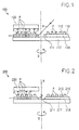
- FIG. 1 shows a first embodiment of a device 100 for detecting a Fluorescent dye F shown in samples P according to the present invention.
- the device 100 comprises a device 110 for exciting the sample P in the sample contained fluorescent dye F, which is in the form of a thin film waveguide 116, the is applied to a substrate 117, is provided.
- the substrate 117 is provided according to FIG. 1 in the form of a circular disk, which is mounted that it can perform a rotational movement D around its center.
- the thin film waveguide 116 On the substrate 117 is the thin film waveguide 116, which has an annular disk shape has, arranged, the center of the annular disc on the axis of rotation lies.
- a light coupling device 111 is on the inside of the ring disk the excitation light from a predetermined irradiation direction R into the thin-film waveguide 116 can be provided.
- Fig. 1 Embodiment is a grid coupler that is concentric about the axis of rotation trained, used. When the light is under a certain, fixed Angle hits the grating coupler 111, it is coupled into the thin-film waveguide in such a way that it spreads parallel to the surface of the thin film waveguide.
- the coupling device 111 can preferably be in the form of a holographically produced one annular grid can be formed.
- the thickness of the thin film waveguide 116 is dependent on the one used Material, in the range of a few 10 nm up to several ⁇ m, so that it is possible through the Grating coupler 111 to couple excitation light into the thin-film waveguide in such a way that only one fashion spreads in it.
- the thickness should be in the range of 100 nm, for synthetic quartz glass with a refractive index of n ⁇ 1.45 the thickness should be in the range of 1-2 ⁇ m.
- the thin film waveguide 116 further includes a surface 112 on which a plurality with respect to a fluorescent dye samples P, of which according to Fig. 1 ten are shown to be applied.
- the device 100 comprises a detection device 120, which is in the form a linear detector line positioned in the radial direction, for example in the form a linear diode array or a CCD line is provided.
- light coming from an irradiation direction R is contains the excitation wavelength, for example monochromatic laser light Excitation wavelength, coupled into the thin film waveguide 116.
- the monochromatic laser light is planted parallel to the surface 112 until it finally comes out of the outer slice edge of the thin film waveguide 116 exits.
- Fluorescent dye F in the samples deposited on the thin film waveguide P is contained by the evanescent field extending along the thin film waveguide 116 moving laser radiation. The through the fluorescent dye F emitted fluorescence radiation is finally emitted by the detection device 120 proven.
- the entire surface 112 is removed from the detection device by the rotary movement D. scanned. Accordingly, detection results for the fluorescent dye F, which is contained in the samples distributed over the entire surface 112, receive.
- the device 120 for detecting and the Movement of surface 112 by the rotational movement of the excitation device 110 originates, synchronized. This will make any location on the surface 112 and thus also each sample with a detection result from the detection device 120 in Relationship set.
- the device 100 shown in FIG. 1 can be modified in a variety of ways.
- the thin-film waveguide can be replaced by a glass plate, into which the light to excite the fluorescent dye to be detected is coupled in that it is guided through it with total reflection.
- This Glass plate preferably has a thickness of a few mm.
- the evanescent field of the laser radiation at the locations of total reflection of the monochromatic laser light for excitation of the fluorescent dye used.
- the fluorescent radiation emitted by the excited fluorescent dye upon de-excitation is finally detected by the detection device 120.
- the excitation light can be through a prism coupler that is ring-shaped and is designed to be firmly connected to the disk.
- the holographic grating coupler 111 can be replaced by a conventional grating coupler, which is produced, for example, by known etching processes become.
- the detector line positioned in the radial direction i.e. the linear diode array or the CCD line can be replaced by a photomultiplier tube.
- This The photomultiplier tube is then arranged to be movable over the entire radius of the disk.
- the movement of the photomultiplier tube can also be used in this case synchronized with the movement of the surface over the radius of the disc be, so that an assignment of the detected radiation to certain samples is possible.
- Such a cavity detector includes for use in that described in FIG. 1 Arrangement a cavity, which is preferably spherical is. This cavity comprises a first opening, which is preferably formed in the form of a gap is.
- the cavity of the cavity detector is thus opposite the device positioned to excite that the first opening of the cavity upon movement of the Device for completely exciting the surface on which samples can be applied are covered. Furthermore, the cavity is provided so that the gap Area of the surface in which the fluorescent radiation from the fluorescent dye is emitted, is opposite.
- the cavity includes a highly reflective inner surface, such as barium sulfate or spectralon. Thanks to this special coating, a Reflectivity of the inner surface of 99.8% can be achieved.
- a second opening is provided in the cavity, into which a first Detector for the detection of fluorescent radiation by the to be detected Fluorescent dye has been emitted, for example in the form of a photomultiplier device, is inserted.
- the one emitted by the excited fluorescent dye Fluorescence radiation is radiated into the cavity, and finally after multiple total reflections on the highly reflective surface by the detector proven.
- the first opening directly opposite the cavity and also the fluorescent radiation generally has no preferred direction in the present Arrangement about 50% of the intensity of fluorescent radiation in the cavity where finally it can be detected, irradiated.
- fluorescence radiation is used in the development according to the invention in the cavity from a solid angle of almost 2 ⁇ steradiene collected and detected there.
- the cavity can also have other geometric shapes, such as one Have a cube shape or the like. Compared to the spherical arrangement However, the number of reflections of the fluorescent radiation in the Increase the cavity until it is detected by the detector, which may the Reflection losses in the cavity can increase.
- the detector of the cavity detector is provided in the form of a photomultiplier.
- a color filter can preferably be placed in front of the photomultiplier wavelength matched by the fluorescent dye F to be detected is.
- a blocking filter device can be installed before the first opening of the cavity be provided.
- This blocking filter device is for that used for excitation Light that is scattered towards the cavity, opaque and for the fluorescence radiation to be detected is transparent.
- additional detectors can be used in corresponding additional openings are used in the cavity can be provided.
- These additional detectors can be constructed identically to the first detector be or be specially adapted to fluorescent radiation, which is in their Wavelength from the fluorescence radiation to be detected with the first detector differs.
- the detectors can also be provided so that they can be used simultaneously Detection of at least one further fluorescent dye is provided are. For this, it may be required to have light with different excitation wavelengths is coupled in via the coupling device.
- the device shown in Fig. 1 with two or several excitation wavelengths can be operated. This can be done, for example the excitation can be modulated in the frequency domain, and the fluorescent radiation with the respective frequency by a correspondingly controlled detection device can be detected.
- fluorescein that is excited to fluoresce at 488 nm can, light of this wavelength must enter the device, for example through an argon laser be irradiated. Since the fluorescence radiation is emitted at 520 nm, a color filter used should be permeable in this area. The same applies to CY5, which can be excited at 633 nm and at 670 nm fluorescence radiation emitted.
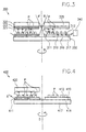
- FIG. 2 shows a second embodiment of a device 200 for the detection of a Fluorescent dye F shown in samples P.
- This device differs from that shown in Fig. 1 in that instead of the grating coupler 111, a coupling mirror 211 is used and furthermore the disk-shaped thin-film waveguide 216 is ground in a trapezoidal shape.
- the coupling mirror 211 is stationary with respect to the direction of radiation R. intended.
- a rotationally symmetrical mirror can also be used, for example firmly connected to the excitation device in the form of a truncated cone be, whereby the mirror also rotates about the axis D.
- FIG. 3 shows a third embodiment of a device 300 for the detection of fluorescent dye F shown in samples P in a schematic sectional view.
- This device differs from the device shown in FIG. 1 in that that the detection device 320 is modified and that in addition to this detection device 320 a further detection device 325, a decoupling device 330 and a further detection device associated with this decoupling device 330 340 are provided.
- the detection device 320 has a lens and / or Aperture system 321. This allows the emitted fluorescent radiation on the Detection device to be focused. Accordingly, with this arrangement Resolution of the detection device can be increased, which opens up the possibility of Number of samples on surface 312 versus a device without one Lens and / or aperture system is operated to increase. Furthermore, the Detection device 320 an to the fluorescent radiation 323 to be detected customized color filter. This can prevent radiation that is not from the fluorescence originates, enters the detection device 320 and the measurement result adulterated.
- the embodiment shown in FIG. 3 includes a further detection device 325, which has the same structure as the detection device 320 has.
- this detection device 325 is opposite the detection device 325, thus at an angle of approximately 180 ° when the device is viewed from above 300, postponed.
- the angle of 180 ° is not a limitation here understand.
- the detector devices can also be used among others Angles to each other are provided.
- the detection device 325 is also provided to detect fluorescent dyes to detect emitted fluorescence radiation. Analogous to that from the direction of radiation R injected light is in the device 300 light that is radiated from R ' is coupled into the excitation device 310 and this light excites fluorescent dyes in the samples located under the detection device 325 on. This light can finally be detected by the detection device 325 become.
- the detection devices 320 and 325 are identical, fluorescent radiation from the detect the same fluorescent dye, with the examination time halved.
- the detection devices 320 and 325 By suitable selection of the detection devices 320 and 325, in particular the one before Color filters provided in these devices can emit fluorescent radiation of the same Fluorescent dye, but from different excitation states results, can be demonstrated at the same time.
- the color filter devices and the incident excitation light can also be provided such that a simultaneous detection of at least one further fluorescent dye F 'is carried out can be.
- the embodiment comprises 3 also a decoupling device 330.
- This decoupling device 3 in the form of a concentric holographic grating coupler, which is attached to the outer edge of the thin-film waveguide.
- the grating coupler attached to the periphery of the thin film waveguide can be part of the fluorescent light that is fed back into the thin film waveguide will be decoupled.
- the grating coupler disperses the emission spectrum, so that with a further, preferably linear CCD detector 340, the sum spectrum of all fluorescent dyes can be detected spectrally.
- FIG. 4 shows a fourth embodiment of a device 400 for the detection of Fluorescent dye F shown in a sample P.
- This device differs from that shown in Fig. 1 only in that the used for coupling the excitation light grating coupler 411 on the outer edge of the annular disk-shaped thin film waveguide 416 is provided. From this embodiment it follows that coupling and decoupling can be interchanged.
- FIG. 4 corresponds to that shown in FIG. and in order to avoid repetition, the remaining components are used only referred to the description in connection with FIG. 1.
- the reference numerals of the corresponding components differ only in their first digit.
- FIGS. 5a and 5b show a fifth embodiment of a device 500 for Detection of fluorescent dye F in samples P in a schematic sectional view and a schematic top view.
- This device differs from the one shown in FIG. 1 in principle in that that the substrate 517 with the thin film waveguide 516 and the coupling device 511 not a rotational movement about an axis, but a translational movement carries out.
- the excitation device 510 which is the substrate 517, the thin film waveguide 516 and the coupling device 511.
- the substrate 517 is in the form of a rectangle educated.
- the thin film waveguide 516 that also has a rectangular shape, applied.
- the light coupling device 511 which also here is preferably provided in the form of a holographic grating.
- the detection device 520 is provided stationary with respect to the direction of irradiation.
- the detection device 520 Since the detection device 520 is stationary with respect to the radiation direction R, there is no change from the different movement for the detection device 520 compared to the detection devices shown in the previous embodiments 120, 220, 320 and 420.
Landscapes
- Health & Medical Sciences (AREA)
- Nuclear Medicine, Radiotherapy & Molecular Imaging (AREA)
- Physics & Mathematics (AREA)
- Life Sciences & Earth Sciences (AREA)
- Chemical & Material Sciences (AREA)
- Analytical Chemistry (AREA)
- Biochemistry (AREA)
- General Health & Medical Sciences (AREA)
- General Physics & Mathematics (AREA)
- Immunology (AREA)
- Pathology (AREA)
- Investigating, Analyzing Materials By Fluorescence Or Luminescence (AREA)
Applications Claiming Priority (3)
| Application Number | Priority Date | Filing Date | Title |
|---|---|---|---|
| DE19815109 | 1998-04-03 | ||
| DE19815109A DE19815109A1 (de) | 1998-04-03 | 1998-04-03 | Vorrichtung zum Nachweis eines Fluoreszenzfarbstoffs |
| US09/286,718 US6317206B1 (en) | 1998-04-03 | 1999-04-06 | Device for the detection of a fluorescent dye |
Publications (2)
| Publication Number | Publication Date |
|---|---|
| EP0947823A2 true EP0947823A2 (fr) | 1999-10-06 |
| EP0947823A3 EP0947823A3 (fr) | 1999-11-17 |
Family
ID=26045272
Family Applications (1)
| Application Number | Title | Priority Date | Filing Date |
|---|---|---|---|
| EP99101241A Withdrawn EP0947823A3 (fr) | 1998-04-03 | 1999-01-22 | Dispositif pour détecter un colorant fluorescent |
Country Status (4)
| Country | Link |
|---|---|
| US (1) | US6317206B1 (fr) |
| EP (1) | EP0947823A3 (fr) |
| JP (1) | JP3187386B2 (fr) |
| DE (1) | DE19815109A1 (fr) |
Cited By (3)
| Publication number | Priority date | Publication date | Assignee | Title |
|---|---|---|---|---|
| EP1120643A3 (fr) * | 2000-01-28 | 2002-03-13 | Leica Microsystems Heidelberg GmbH | Dispositif pour la détection de la lumière fluorescente de plusieurs échantillons ponctuels |
| DE102004039564B4 (de) * | 2004-08-13 | 2006-06-29 | Institut für Lasertechnologien in der Medizin und Meßtechnik an der Universität Ulm | Vorrichtung zum optischen Screening von Oberflächen biologischer Proben in zweidimensionaler Anordnung |
| WO2007010469A1 (fr) | 2005-07-21 | 2007-01-25 | Koninklijke Philips Electronics N. V. | Dispositif pour detecter une excitation faisant appel a un agencement de plusieurs points lumineux |
Families Citing this family (14)
| Publication number | Priority date | Publication date | Assignee | Title |
|---|---|---|---|---|
| DE10056384C2 (de) * | 2000-11-14 | 2003-06-05 | Leica Microsystems | Vorrichtung zur Messung der Lebensdauer eines angeregten Zustandes in einer Probe und Verwendung der Vorrichtung |
| US7545496B2 (en) * | 2003-06-25 | 2009-06-09 | Koninklijke Philips Electronics N.V. | Support with a surface structure for sensitive evanescent-field detection |
| US6987274B1 (en) * | 2004-08-31 | 2006-01-17 | Palo Alto Research Center Incorporated | Light detection and imaging system and method including an array of sensors |
| US20070247628A1 (en) * | 2004-09-10 | 2007-10-25 | Wallac Oy | Instrumentation and Method Adapted For Optical Measurement of an Amplified Luminescent Proximity Homogeneous Assay |
| RU2414695C2 (ru) * | 2004-12-10 | 2011-03-20 | Конинклейке Филипс Электроникс Н.В. | Устройство для многоточечного исследования |
| SE529254C2 (sv) * | 2005-06-17 | 2007-06-12 | Aamic Ab | Optiskt testsystem |
| US8207509B2 (en) * | 2006-09-01 | 2012-06-26 | Pacific Biosciences Of California, Inc. | Substrates, systems and methods for analyzing materials |
| US7943908B2 (en) * | 2007-01-22 | 2011-05-17 | University Of Maryland | Sensor system with surface-plasmon-polariton (SPP) enhanced selective fluorescence excitation and method |
| EP1965195A1 (fr) * | 2007-02-28 | 2008-09-03 | Hitachi High-Technologies Corporation | Appareil de mesure de la luminosité |
| EP2331934B1 (fr) | 2008-09-16 | 2020-01-01 | Pacific Biosciences of California, Inc. | Appareil d'analyse comprenant substrat de guides d'ondes en mode zéro |
| CN102830224B (zh) * | 2012-08-28 | 2014-09-24 | 天津市先石光学技术有限公司 | 用于均相发光免疫检测的光路切换机构 |
| US9352256B2 (en) | 2013-03-14 | 2016-05-31 | The Boeing Company | Filtration systems and methods for filtering particles of a predetermined substance |
| US20140260688A1 (en) * | 2013-03-14 | 2014-09-18 | The Boeing Company | Sensor assembly using micropillars and method of use |
| US9290219B2 (en) | 2013-03-14 | 2016-03-22 | The Boeing Company | Locomotion system and method of controlling a robotic device |
Citations (1)
| Publication number | Priority date | Publication date | Assignee | Title |
|---|---|---|---|---|
| EP0949502A2 (fr) * | 1998-03-23 | 1999-10-13 | Bodenseewerk Perkin-Elmer Gmbh | Dispositif de détection de colorant fluorescent |
Family Cites Families (9)
| Publication number | Priority date | Publication date | Assignee | Title |
|---|---|---|---|---|
| US3975084A (en) * | 1973-09-27 | 1976-08-17 | Block Engineering, Inc. | Particle detecting system |
| IT1153797B (it) * | 1980-04-03 | 1987-01-21 | Luciano Gasbarro | Apparecchio per la lettura ottico-densitometrica di campioni, in specie elettroforetici, con supporto discoidale porta-campioni |
| US5670113A (en) * | 1991-12-20 | 1997-09-23 | Sibia Neurosciences, Inc. | Automated analysis equipment and assay method for detecting cell surface protein and/or cytoplasmic receptor function using same |
| CA2162996C (fr) * | 1993-05-18 | 2008-02-05 | James N. Herron | Appareil et methodes pour fluoro-immuno-essais homogenes multi-analysats |
| JP3326708B2 (ja) * | 1993-08-31 | 2002-09-24 | 日水製薬株式会社 | 光学的測定装置およびその方法 |
| MXPA96005828A (es) * | 1994-05-27 | 2005-07-15 | Novartis Ag Tambien Denominada | Proceso para detectar luminescencia excitada evanescentemente. |
| KR19990014709A (ko) | 1995-05-12 | 1999-02-25 | 한스루돌프하우스 | 센서 플랫폼 및 감쇠 여기된 발광을 이용한 복수 분석물의병렬 검출 방법 |
| US6143247A (en) * | 1996-12-20 | 2000-11-07 | Gamera Bioscience Inc. | Affinity binding-based system for detecting particulates in a fluid |
| JP3287775B2 (ja) * | 1996-02-29 | 2002-06-04 | 松下電器産業株式会社 | 蛍光体の量子効率測定方法および測定装置 |
-
1998
- 1998-04-03 DE DE19815109A patent/DE19815109A1/de not_active Withdrawn
-
1999
- 1999-01-22 EP EP99101241A patent/EP0947823A3/fr not_active Withdrawn
- 1999-04-05 JP JP09811699A patent/JP3187386B2/ja not_active Expired - Fee Related
- 1999-04-06 US US09/286,718 patent/US6317206B1/en not_active Expired - Lifetime
Patent Citations (1)
| Publication number | Priority date | Publication date | Assignee | Title |
|---|---|---|---|---|
| EP0949502A2 (fr) * | 1998-03-23 | 1999-10-13 | Bodenseewerk Perkin-Elmer Gmbh | Dispositif de détection de colorant fluorescent |
Non-Patent Citations (1)
| Title |
|---|
| SLOPER A N; DEACON J K; FLANAGAN M T: "A PLANAR INDIUM PHOSPHATE MONOMODE WAVEGUIDE EVANESCENT FIELD IMMUNOSENSOR", SENSORS AND ACTUATORS B, vol. 1, January 1990 (1990-01-01), pages 589 - 591, XP022084350, DOI: doi:10.1016/0925-4005(90)80279-9 * |
Cited By (6)
| Publication number | Priority date | Publication date | Assignee | Title |
|---|---|---|---|---|
| EP1120643A3 (fr) * | 2000-01-28 | 2002-03-13 | Leica Microsystems Heidelberg GmbH | Dispositif pour la détection de la lumière fluorescente de plusieurs échantillons ponctuels |
| US6603553B1 (en) | 2000-01-28 | 2003-08-05 | Leica Microsystems Heidelberg Gmbh | Arrangement for detecting fluorescent light from a plurality of sample points |
| DE10024132B4 (de) * | 2000-01-28 | 2007-03-22 | Leica Microsystems Cms Gmbh | Anordnung zur Detektion von Fluoreszenzlicht mehrerer Probenpunkte |
| DE102004039564B4 (de) * | 2004-08-13 | 2006-06-29 | Institut für Lasertechnologien in der Medizin und Meßtechnik an der Universität Ulm | Vorrichtung zum optischen Screening von Oberflächen biologischer Proben in zweidimensionaler Anordnung |
| WO2007010469A1 (fr) | 2005-07-21 | 2007-01-25 | Koninklijke Philips Electronics N. V. | Dispositif pour detecter une excitation faisant appel a un agencement de plusieurs points lumineux |
| EP1910809A1 (fr) * | 2005-07-21 | 2008-04-16 | Koninklijke Philips Electronics N.V. | Dispositif pour detecter une excitation faisant appel a un agencement de plusieurs points lumineux |
Also Published As
| Publication number | Publication date |
|---|---|
| DE19815109A1 (de) | 1999-10-07 |
| US6317206B1 (en) | 2001-11-13 |
| EP0947823A3 (fr) | 1999-11-17 |
| JP3187386B2 (ja) | 2001-07-11 |
| JPH11326209A (ja) | 1999-11-26 |
Similar Documents
| Publication | Publication Date | Title |
|---|---|---|
| DE60037184T2 (de) | Abbildungssystem für optischen bildabtaster | |
| EP0834066B1 (fr) | Procede et dispositif permettant de mettre en evidence des reactions et des interactions d'ordre physique, chimique, biologique ou biochimique | |
| EP0947823A2 (fr) | Dispositif pour détecter un colorant fluorescent | |
| DE69730030T2 (de) | Konfokales Spektroskopiesystem und -verfahren | |
| DE3610165C2 (fr) | ||
| DE19653413C2 (de) | Rastermikroskop, bei dem eine Probe in mehreren Probenpunkten gleichzeitig optisch angeregt wird | |
| DE3856381T2 (de) | Kathetersystem zur abbildung | |
| DE10225838B4 (de) | Verfahren zur Scanmikroskopie, Scanmikroskop und Vorrichtung zum Codieren eines Beleuchtungslichtstrahles | |
| DE10008006C2 (de) | SPR-Sensor und SPR-Sensoranordnung | |
| DE3874125T2 (de) | Uv-abtastsystem fuer zentrifuge. | |
| EP0961945A1 (fr) | Dispositif de balayage lumineux | |
| DE2415049A1 (de) | Mehrkanalanalysator zur optischen messung von bei der chromatographie von fluessigkeiten erhaltenen fraktionen | |
| DE2364069B2 (de) | Spektralphotometer | |
| DE69203195T2 (de) | Vorrichtung zur Spektralphotometrie mit Spektralbandfilterung. | |
| EP1507137B1 (fr) | Procédé et dispositif pour l'inspection dépendante de la polarisation et pour l'inspection par résolution spatiale d'une surface ou d'une couche | |
| WO2016173662A1 (fr) | Appareil de mesure d'émission de lumière et procédé pour la mesure d'une d'émission de lumière | |
| DE19828547C2 (de) | Anordnung zum Nachweis biomolekularer Reaktionen und Wechselwirkungen | |
| DE60014944T2 (de) | Vorrichtung zur bestimmung der räumlichen verteilung der spektralen emission eines objekts | |
| DE60205406T2 (de) | Optisches zweiwellenlängen-fluoreszenzanalysegerät | |
| EP0427943B1 (fr) | Capteur à fibres optiques servant à la détection d'effets photothermiques | |
| EP3614130B1 (fr) | Dispositif pour la détermination de caractéristiques optiques d'échantillons | |
| DE2212498A1 (de) | Raman-Spektrometer | |
| DE19728966C2 (de) | Bildgebendes Spektrometer | |
| DE10155142C2 (de) | Dunkelfeld-Abbildungsvorrichtung zur ortsaufgelösten Dunkelfeldabbildung einer flächigen Probe | |
| DD159567B1 (de) | Spektralfluorometer |
Legal Events
| Date | Code | Title | Description |
|---|---|---|---|
| PUAI | Public reference made under article 153(3) epc to a published international application that has entered the european phase |
Free format text: ORIGINAL CODE: 0009012 |
|
| PUAL | Search report despatched |
Free format text: ORIGINAL CODE: 0009013 |
|
| AK | Designated contracting states |
Kind code of ref document: A2 Designated state(s): DE FR GB IT |
|
| AX | Request for extension of the european patent |
Free format text: AL;LT;LV;MK;RO;SI |
|
| AK | Designated contracting states |
Kind code of ref document: A3 Designated state(s): AT BE CH CY DE DK ES FI FR GB GR IE IT LI LU MC NL PT SE |
|
| AX | Request for extension of the european patent |
Free format text: AL;LT;LV;MK;RO;SI |
|
| 17P | Request for examination filed |
Effective date: 20000114 |
|
| AKX | Designation fees paid |
Free format text: DE FR GB IT |
|
| 17Q | First examination report despatched |
Effective date: 20061229 |
|
| STAA | Information on the status of an ep patent application or granted ep patent |
Free format text: STATUS: THE APPLICATION IS DEEMED TO BE WITHDRAWN |
|
| 18D | Application deemed to be withdrawn |
Effective date: 20170307 |