EP0947865A1 - Coupleur optique à voies multiples avec lentille - Google Patents
Coupleur optique à voies multiples avec lentille Download PDFInfo
- Publication number
- EP0947865A1 EP0947865A1 EP99106016A EP99106016A EP0947865A1 EP 0947865 A1 EP0947865 A1 EP 0947865A1 EP 99106016 A EP99106016 A EP 99106016A EP 99106016 A EP99106016 A EP 99106016A EP 0947865 A1 EP0947865 A1 EP 0947865A1
- Authority
- EP
- European Patent Office
- Prior art keywords
- ports
- lens
- optical
- face
- linear array
- Prior art date
- Legal status (The legal status is an assumption and is not a legal conclusion. Google has not performed a legal analysis and makes no representation as to the accuracy of the status listed.)
- Granted
Links
Images


Classifications
-
- G—PHYSICS
- G02—OPTICS
- G02B—OPTICAL ELEMENTS, SYSTEMS OR APPARATUS
- G02B6/00—Light guides; Structural details of arrangements comprising light guides and other optical elements, e.g. couplings
- G02B6/24—Coupling light guides
- G02B6/26—Optical coupling means
- G02B6/28—Optical coupling means having data bus means, i.e. plural waveguides interconnected and providing an inherently bidirectional system by mixing and splitting signals
- G02B6/293—Optical coupling means having data bus means, i.e. plural waveguides interconnected and providing an inherently bidirectional system by mixing and splitting signals with wavelength selective means
- G02B6/29346—Optical coupling means having data bus means, i.e. plural waveguides interconnected and providing an inherently bidirectional system by mixing and splitting signals with wavelength selective means operating by wave or beam interference
- G02B6/29361—Interference filters, e.g. multilayer coatings, thin film filters, dichroic splitters or mirrors based on multilayers, WDM filters
- G02B6/2937—In line lens-filtering-lens devices, i.e. elements arranged along a line and mountable in a cylindrical package for compactness, e.g. 3- port device with GRIN lenses sandwiching a single filter operating at normal incidence in a tubular package
-
- G—PHYSICS
- G02—OPTICS
- G02B—OPTICAL ELEMENTS, SYSTEMS OR APPARATUS
- G02B6/00—Light guides; Structural details of arrangements comprising light guides and other optical elements, e.g. couplings
- G02B6/24—Coupling light guides
- G02B6/26—Optical coupling means
- G02B6/28—Optical coupling means having data bus means, i.e. plural waveguides interconnected and providing an inherently bidirectional system by mixing and splitting signals
- G02B6/293—Optical coupling means having data bus means, i.e. plural waveguides interconnected and providing an inherently bidirectional system by mixing and splitting signals with wavelength selective means
- G02B6/29379—Optical coupling means having data bus means, i.e. plural waveguides interconnected and providing an inherently bidirectional system by mixing and splitting signals with wavelength selective means characterised by the function or use of the complete device
- G02B6/2938—Optical coupling means having data bus means, i.e. plural waveguides interconnected and providing an inherently bidirectional system by mixing and splitting signals with wavelength selective means characterised by the function or use of the complete device for multiplexing or demultiplexing, i.e. combining or separating wavelengths, e.g. 1xN, NxM
-
- G—PHYSICS
- G02—OPTICS
- G02B—OPTICAL ELEMENTS, SYSTEMS OR APPARATUS
- G02B6/00—Light guides; Structural details of arrangements comprising light guides and other optical elements, e.g. couplings
- G02B6/24—Coupling light guides
- G02B6/36—Mechanical coupling means
- G02B6/38—Mechanical coupling means having fibre to fibre mating means
- G02B6/3807—Dismountable connectors, i.e. comprising plugs
- G02B6/3833—Details of mounting fibres in ferrules; Assembly methods; Manufacture
Definitions
- This invention relates to optical coupling technology, and more particularly relates to a multi-port optical device utilizing a lens and preferably a graded index lens.
- optical fiber technology light signals are used in place of electrical signals to transmit information from one place to another.
- transparent optical fibers carry light signals bearing the transmitted information.
- One of the desired components in fiber optic technology is a low cost, high-performance coupler by which light signals sent on one optical fiber may be divided or split into light signals on several optical fibers. Conversely in some splitter/couplers light signals on more than one optical fiber may be combined into one fiber by such a coupler.
- This is a straightforward matter in the more common electrical technology. Wires may be spliced together to form multiple branches. Electrical signals sent along one wire will naturally propagate along all branches connected to the wire; and the converse situation is also true.
- Couplers are some of the most ubiquitous of all passive discrete optical components found in most optical communication systems. However until now, individual discrete couplers have been used. Thus, there is a need for a single device that will provide the function of multiple coupling devices in a single coupling element.
- splitters, couplers and mulitiplexors or demultiplexors are combined to form optical devices with desired functionality.
- the complexity, size and cost of these combined devices increases proportionally.
- such optical circuit may become unwieldy with regards to maintenance or repair as the number of ports increases.
- a splitter combiner/multiplexor that is to perform the function of splitting an optical signal of a first wavelength ⁇ 1 into 16 sub-signals of wavelength ⁇ 1, and combining each of these sub-signals with waveguides carrying a second wavelength ⁇ 2, can be configured using a plurality of 1x2 splitters and 16 wavelength multiplexing filters for combining each of the 16 sub-signals of wavelength ⁇ 1 with the 16 signals having the second wavelength ⁇ 2.
- the losses resulting from each coupling for example each splitter and filter node, are considerable, and cumulative.
- the cost of providing a device that has pluralty of 1x2 splitters and 16 WDM couplers is quite substantial.
- a multi-port optical device comprising:
- a multi-port optical device comprising:
- a multi-port optical device comprising:
- this invention provides complex functionality using very few components, by taking advantage of currently available optical fibre arrays, and symmetrical properties of optical lenses, and preferably GRIN lenses. Further advantageously, this invention allows bulk optical components such as GRIN lenses and optical fibres to be combined with monolithic waveguide technology in a new and unexpected manner, whereby an array of waveguides disposed within a monolithic waveguide chip can be optically coupled with one or more linear arrays of waveguides such as optical fibres via lensing techniques that utilize a region of the lens, heretofore not utilized in this manner. As a result of this integration of technologies, the number of components is substantially reduced from those required before realizing similar functionality.
- the fiber optic coupler has a first optical fiber 8 fixed to one end of a GRIN (GRaded INdex) lens 9 along the optical axis (shown as a dotted line) of the lens 12. At the other end of the lens 9 and also centered about its optical axis is fixed a bundle of N second optic fibers 7.
- GRIN GRaded INdex
- the coupler 5 acts as a splitter
- light from the first fiber 8 is split and is transmitted along each of the N second fibers 7.
- the coupler acts as a combiner where first and second fibers switch roles, i.e., light from any one of the N second fibers 7 is transmitted through the GRIN lens 9 to the first fiber 8.
- the fiber 8 thus combines the signals from the fibers 7; the coupler acts as a combiner
- an optical coupler 10 having an optical element in the form of a splitter filter 16 interposed between collimating inwardly facing ends of a first quarter pitch GRIN lens 2 and a second quarter pitch GRIN lens 3.
- the term optical port referred to hereafter shall be understood to be a predetermined location and/or coupling at a lens end face for launching or receiving light from in the form of an optical signal.
- the first GRIN lens 2 is shown having an input end having input ports 17a and 19a, and a collimating output end.
- the input end further includes output ports 17b and 19b. Since the refractive index of the lens 2 is symmetrical about its optical axis 11 (shown by a dotted line through the center of the lens), pairs of ports are positioned symmetrically about the optical axis 11 such that input port 17a and output port 17b are equidistant from, and on opposite sides of the optical axis 11.
- Input ports 19a and 19b are more distant from the optical axis 11 and are similarly equidistant from it.
- a signal launched into port 17a will reflect from the splitter filter 16 and back into output port 17b.
- a signal launched into port 19a will reflect into port 19b.
- the collimating GRIN lenses 2 and 3 are matched, having a similar refractive index profile, and if they share a common optical axis, output signals launched into the input ports 17a and 19a, not reflecting back to 17b and 19b respectively, will exit the output ports 17c and 19c respectively on the output (non-collimating) end of the second GRIN lens 14.
- Input port 17a and output port 17c are also substantially equidistant from the optical axis.
- optical element 16 described heretofore as a splitter filter 16 may be any at least partially reflecting, partially transmitting discrete optical element, or coating applied to an end of one of the lenses. Furthermore, it may have properties that are dependent upon the wavelength of light incident upon the filter, or, it may have properties that vary with incident angle or incident position on the element.
- the filter may be an attenuating filter a bandpass filter or a wideband splitter filter.
- a GRIN lens 30 of a device 8 input ports and 8 output ports on a same end face is illustrated.
- an optical filter similar to filter 16 shown in Fig. 2a and another same GRIN lens complementary to the lens 30.
- a transmitting port optically aligned with a receiving port is equidistant from the optical axis 11 and will be on opposite sides of the optical axis 11.
- input port 10a is coupled through a reflective means 16 with output port 10b.
- input port 11a is coupled through the same reflective means to output port 11b, and so on, and input port 17a is coupled to output port 17b on the opposite side of the optical axis 11. All of these paired ports are equidistant from and on opposite sides of the optical axis. Furthermore, and not shown, ports 10c to 17c are coupled with ports 10b through 17b from the other compelmentary GRIN lens 30 (not shown).
- the optical arrangement is somewhat limited.
- the input waveguides shown at the end face of the lens 30 in Fig. 3 are limited to being disposed along a radius, along one half of the end face, from the optical axis outward illustrated by ports 10a to 17a.
- all of the ports must be equally spaced from the optical axis.
- One limitation to this design is that a substantial portion of the end face about the periphery of the lens is utilized.
- a more central region of the lens confined within the region indicated by circle 32.
- the arrangement of Fig. 3 is limited, since only a length less than the radius of the lens can be used for either input or output optical ports, and large closely packed arrays of for example, 16 or 32 optical waveguides would not be practicably coupled to standard commercially available GRIN lenses having a diameter of about 2 mm.
- Fig. 4 in accordance with this invention, provides an alternative arrangement that allows a great number of input and output ports to be conveniently coupled to one another through a filter such as 16 shown in Fig. 2 and as well is compatible with commercially available ribbon fibre.
- a greater number of ports can be provided in the embodiment shown in Fig. 4 than Fig. 3 and, ribbon fibre blocks are available that conveniently provide ports as shown in Fig. 4.
- a line of input ports 10a to 21a are shown within the circle 32 forming a linear array indicated by the dotted line in the figure which passes through the ports.
- Spaced and parallel to the input ports 10a to 21a are a set of output ports forming a second linear array defined by ports 10b to 21b parallel to the first array of ports.
- Both linear arrays of ports are shown to be offset from the optical axis and parallel to a dotted line passing through the optical axis. Hence, the top array of input ports is optically coupled with the bottom array of output ports.
- Figs 5, 5a and 5b show a device in accordance with the invention, having only 4 input ports and 4 output ports at a same end, for the purpose of explanation of the optical circuit.
- an optical filter 16 is shown sandwiched between two GRIN lenses 50 and 53.
- Input signals having a first wavelength ⁇ 1 are launched into a first linear array of ports 10a through 13a via optical fibres. These input signals are reflected by the filter 16 and couple into the second linear array defined by ports 10b through 13b, which are parallel to the first linear array of ports.
- a second group of signals having a wavelength of ⁇ 2 are launched into waveguides and enter the lens 53 at ports 10c through 13c and pass through the filter 16 to couple into the optical fibres at ports 10b through 13b to combine with the signals having a wavelength ⁇ 1.
- a more detailed view of the arrangement of the ports is shown in Figs. 5a and 5b.
- FIGs. 4, 5, 5a and 5b are most conveniently realized when used with an optical fibre block 100 such as the one shown in Figs 10 and 11.
- Two ribbons 102 and 104 of optical fibres are contained within the block 100.
- the ribbons 102 and 104 are linear parallel arrays of optical waveguides terminating at an end face of the block.
- two diagonal lines are shown connecting opposite ends of opposite arrays.
- a first diagonal is shown between fibre A 1 and B 16 and a second diagonal is shown between fibre A 16 and B 1 .
- the intersection of these two diagonals is a point 110, which is coincident with the optical axis of the lens it is being coupled with to assist in alignment of the fibres with the lens.
- the block 100 can be coupled directly to an end face of a standard GRIN lens. Furthermore, after approximately aligning the intersection point 110 with the optical axis of the lens, further tuning may be done to both arrays at once, by shifting and rotating the block 100 while providing light beams to one of the arrays, while testing for optimum coupling by detecting the intensity at the other array. When the best position is located the block may be secured to the lens, or alternatively the relative positioning may be fixed.
- a GRIN lens pair is shown having an optical filter 16 disposed between the lenses 2 and 3.
- the beams launched into the end face of the lens 2 do not focus along a straight line at an end face of the lens 3, but focus along a curved line.
- Fig. 13 shows an embodiment wherein a block 120 has a curved face 122. This can be achieved by polishing a curve having a desired radius into a block having a flat end face.
- a communications system is shown wherein 16 optical fibres 10 1 to 10 16 (not all shown) provide bi-directional communication at a wavelength of 1330 nm between a transmitting end (at the left) and 16 subscribers 30a, 30b, 30c, to 30p (at the right).
- Optical multiplexers 60a to 60p are disposed intermediate the two ends of each of the optical fibres 10 1 to 10 16 .
- the multiplexers can be of various known types, for example as is shown in Fig. 8, wherein each multiplexer 60a consists of a dichroic optical filter 16 sandwiched between two back to back collimating GRIN lenses 2 and 3.
- Fig. 6 works in the following manner.
- Each of the 16 signals A', B', C', ....P' are transmitted between subscribers and a single corresponding transmitting and receiving end A, B, C,... P respectively.
- a single 1550 nm signal to be multiplexed is divided by a 1 to 16 splitter 62 and the 16 branches carrying 1550 nm wavelengths are each directed to a different one of the 16 multiplexers 60a to 60p thereby providing a same 1550 nm signal having 1/16 th of the power of the original single signal to each subscriber.
- Fig. 7 is a more detailed diagram showing the 1:16 splitter 62.
- 1:16 splitter is made from a plurality of 1:2 splitters forming a 1:8 splitter and the outputs of the 1:8 splitter are further divided by 1:2 splitters to form a 1:16 splitter.
- 1:2 splitters are further divided by 1:2 splitters to form a 1:16 splitter.
- other configurations are possible depending upon the components available.
- the circuit of Figs. 9a and 9b includes a monolithic glass block 91 having a dividing network 92 of spaced waveguides disposed therein, via any well known technique that will provide a suitable refractive index difference between the waveguides region and the adjacent glass region serving as a cladding such as ion diffusion or ion exchange processes.
- Adjacent to the blocks 90 are two substantially quarter pitch graded index (GRIN) lenses 94 and 96 that provide a means of guiding, collimating and focusing light as required and as will be described.
- GRIN substantially quarter pitch graded index
- a wideband filter 95 designed to pass light of wavelength 1330 nm and reflect light of wavelength 1550 nm is disposed between the two GRIN lenses 94 and 96.
- the filter 95 can be deposited or coated directly onto the end face of one of the lenses 94 or 96 or alternatively can be deposited or coated onto a light transmissive substrate such as glass which is sandwiched between the lenses.
- the dividing network of waveguides 92 within the waveguide block 91 is in the form of a 1:16 splitter having a single input optical fibre waveguide held in a holder 97.
- the network divides a single input waveguide into a branch network of 16 substantially parallel waveguides at another end with a spacing of 127 ⁇ m between adjacent waveguides core centres.
- these waveguides at the end of the block 91 adjacent the GRIN lens 94 are optically aligned with the linear array 102 at an end of the lens 96 via.
- the filter 95 is designed to allow light of wavelengths of about 1550 nm to pass therethrough and to reflect light of about 1300 nm.
- the circuit shown in Figs. 9a and 9b operates in the following manner.
- an input signal having a wavelength of 1550 nm is launched onto the single optical fibre waveguide.
- the signal is subsequently divided by the splitter network and propagates along 16 waveguides toward the GRIN lens 94.
- Each of the sub-beams exiting the 16 end faces of the 1:16 splitter network propagate through the GRIN lens 94 and are directed toward the filter 95 as substantially collimated sub-beams.
- the 16 sub-beams Upon being incident upon the filter 95, the 16 sub-beams are passed through the filter 95 to couple with the linear array of optical fibres 102 contained within block 100.
- the 16 sub-beams of light having a wavelength of 1550 nm then propagate into the waveguides 102.
- Light of having a wavelength of 1300 nm is simultaneously launched into the linear array of waveguides 104 and is reflected to the linear array of waveguides 102 so that both wavelengths couple together.
- This architecture conveniently allows the 1330 nm signal to pass bi-directionally from one end of the device to the other, (between waveguides 102 to 104) and at the same time provides a means of multiplexing the 1550 nm signal into each of the 16 subscriber's homes.
- this circuit is limited to 16 subscribers, in practice it is limited by the number of waveguides that can conveniently be placed within a linear array at the end face of a lens.
- One particular advantage of this circuit is that standard inter-waveguide spacing of 127 ⁇ m can be provided at one end of the block(s) 52 and/or 58, compatible with commercially available linear array ribbon fibre for coupling signals into and out of the device.
- the optical element in the various embodiments may take the form of any optical element for changing a characteristic such as intensity, or direction of light incident upon it. It may be in the form of a wavelength dependent splitter, a wavelength independent splitter/filter, a splitter/coupler, an attenuator, or simply a means for reflecting an optical signal between two ports equidistant from the optical axis of a GRIN lens.
- the block holding the arrays of waveguides can have more than two linear arrays of optically alignable waveguides.
- a first linear array of optical fibres is shown defining an line 132a and a complementary second linear array 132b is shown equally spaced from the centre C of the block 130.
- Third and forth linear arrays defining the lines 134a and 134b are also shown, wherein the third array of waveguides is optically alignable with the fourth array via a lens.
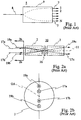
- Figs. 15 and 16 an arrangement of GRIN lenses is shown that allows all input/output waveguides to be disposed at one end.
- Fig. 15 shows a beam 154 launched into a first lens 150 propagating through the first lens, a filter 159, a second and third lens 151 and 152 to be circulated backward via a mirrored surface 157 to an output port 156.
- Fig. 16 a similar arrangement is shown, however the lens 152 is shown having its optical axis offset from the two lenses 150 and 151.
- this allows all input an output waveguides to be disposed at a same end of the device. This is particularly important. Firstly, providing a hermetically sealed package of components is considerably easier when all ports are disposed at a single end of a device. Secondly, there is less mechanical stress on a package of optical components when all ports are disposed at a single end.
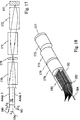
- Fig. 17 illustrates an embodiment of this invention wherein the input output linear arrays 180 and 182 and the single input waveguide 184 are disposed at a single end of the device. From the left to the right end of the device there is a waveguide block 91 having a dividing network as is shown in Fig.9a.
- the two linear arrays of waveguides 180 and 182 are disposed on the top and bottom of the waveguide block respectively, the block being optically coupled with a first lens 170.
- An optical filter 179 is designed to reflect light of a wavelength ⁇ 1 and is designed to pass light of a wavelength ⁇ 2.
- Two collimating lenses 171 and 172 are offset from each other and the lens 172 has a reflective surface such as a mirror 177 at an end.
- These lenses are disposed to guide the beams from the divider network of the block 91 back to ports of the array 180 for combination with the light of wavelength ⁇ 1.
- This embodiment is particularly well suited to being disposed within a hermetically sealed package. This embodiment provides the same functionality as the embodiment of Fig. 9a.
- Fig. 18 illustrates the same embodiment shown in Fig. 17 in perspective view.
Landscapes
- Physics & Mathematics (AREA)
- General Physics & Mathematics (AREA)
- Optics & Photonics (AREA)
- Optical Couplings Of Light Guides (AREA)
- Optical Integrated Circuits (AREA)
Applications Claiming Priority (2)
| Application Number | Priority Date | Filing Date | Title |
|---|---|---|---|
| US52879 | 1998-04-01 | ||
| US09/052,879 US6044187A (en) | 1998-04-01 | 1998-04-01 | Multi-port fiber optical device |
Publications (2)
| Publication Number | Publication Date |
|---|---|
| EP0947865A1 true EP0947865A1 (fr) | 1999-10-06 |
| EP0947865B1 EP0947865B1 (fr) | 2002-06-05 |
Family
ID=21980508
Family Applications (1)
| Application Number | Title | Priority Date | Filing Date |
|---|---|---|---|
| EP99106016A Expired - Lifetime EP0947865B1 (fr) | 1998-04-01 | 1999-03-25 | Coupleur optique à voies multiples avec lentille |
Country Status (5)
| Country | Link |
|---|---|
| US (1) | US6044187A (fr) |
| EP (1) | EP0947865B1 (fr) |
| JP (1) | JPH11326688A (fr) |
| CA (1) | CA2267017A1 (fr) |
| DE (1) | DE69901650T2 (fr) |
Cited By (8)
| Publication number | Priority date | Publication date | Assignee | Title |
|---|---|---|---|---|
| WO2001037010A3 (fr) * | 1999-11-16 | 2001-11-22 | Whitaker Corp | Connecteur de fibres optiques comportant plusieurs interfaces en reseau |
| EP0997754A3 (fr) * | 1998-10-29 | 2002-06-19 | Jds Fitel Inc. | Manchon avec lentille utilisé avec fibres optiques |
| WO2002070987A1 (fr) * | 2001-03-01 | 2002-09-12 | Corning Incorporated | Systeme et procede permettant d'aligner deux axes optiques l'un sur l'autre |
| EP1126294A3 (fr) * | 2000-02-17 | 2003-03-12 | JDS Uniphase Inc. | Configuration optique pour un égalisateur de gain dynamique et multiplexeur à insertion/extraction configurable |
| US6567586B2 (en) | 2001-07-24 | 2003-05-20 | Corning Incorporated | Dual fiber collimator |
| WO2018144696A1 (fr) * | 2017-02-02 | 2018-08-09 | Alliance Fiber Optic Products, Inc. | Ensemble optique de multiplexage par répartition en longueur d'onde à densité de voie accrue |
| US10313045B2 (en) | 2016-11-17 | 2019-06-04 | Alliance Fiber Optic Products, Inc. | Wavelength-division multiplexing optical assembly with increased lane density |
| US11973580B2 (en) | 2021-09-30 | 2024-04-30 | Corning Research & Development Corporation | Redundant wavelength division multiplexing devices and methods for processing light using same |
Families Citing this family (10)
| Publication number | Priority date | Publication date | Assignee | Title |
|---|---|---|---|---|
| CA2217688C (fr) * | 1997-10-07 | 2006-12-05 | Gary Duck | Transmission de la lumidre dans un dispositif monolithique guide d'ondes |
| US6535668B2 (en) * | 1999-02-22 | 2003-03-18 | Alliance Fiber Optics Products, Inc. | Retro-reflective multi-port filter device with triple-fiber ferrule |
| US7035484B2 (en) * | 2002-04-12 | 2006-04-25 | Xtellus, Inc. | Tunable optical filter |
| US8155314B2 (en) * | 2002-06-24 | 2012-04-10 | Microsoft Corporation | Systems and methods for securing video card output |
| JP2004133038A (ja) * | 2002-10-08 | 2004-04-30 | Nippon Sheet Glass Co Ltd | フィルタモジュール |
| US7660502B1 (en) | 2006-07-12 | 2010-02-09 | Wavefront Research, Inc. | Optical interconnect and connector devices |
| CN102645705A (zh) * | 2011-02-21 | 2012-08-22 | 华为技术有限公司 | 一种波分复用器、光开关装置及光开关控制方法 |
| TWI511477B (zh) * | 2011-12-07 | 2015-12-01 | Hon Hai Prec Ind Co Ltd | 光收發裝置 |
| JP6459334B2 (ja) * | 2014-09-18 | 2019-01-30 | 住友電気工業株式会社 | フェルール及び光接続構造 |
| WO2018229992A1 (fr) * | 2017-06-16 | 2018-12-20 | 京セラ株式会社 | Module de connecteur optique |
Citations (6)
| Publication number | Priority date | Publication date | Assignee | Title |
|---|---|---|---|---|
| US4111524A (en) * | 1977-04-14 | 1978-09-05 | Bell Telephone Laboratories, Incorporated | Wavelength division multiplexer |
| US4299488A (en) * | 1979-11-23 | 1981-11-10 | Bell Telephone Laboratories, Incorporated | Time-division multiplexed spectrometer |
| FR2551886A1 (fr) * | 1983-09-09 | 1985-03-15 | Sopelem | Dispositif de couplage de cables de fibres optiques |
| EP0194612A2 (fr) * | 1985-03-14 | 1986-09-17 | Firma Carl Zeiss | Multiplexeur ou démultiplexeur de longueurs d'ondes |
| JPH01178903A (ja) * | 1987-12-29 | 1989-07-17 | Hoya Corp | 光分波・分岐装置 |
| EP0722101A1 (fr) * | 1995-01-13 | 1996-07-17 | SEIKOH GIKEN Co., Ltd. | Embouteur fibre optique et coupleur optique construi utilisant l'embouteur fibre optique |
Family Cites Families (3)
| Publication number | Priority date | Publication date | Assignee | Title |
|---|---|---|---|---|
| US5050954A (en) * | 1990-01-12 | 1991-09-24 | At&T Bell Laboratories | Multiport optical devices |
| US5287424A (en) * | 1992-07-06 | 1994-02-15 | Sheem Sang K | Optical fiber coupler with overlapping core-extensions, and manufacturing methods of the same |
| US5930418A (en) * | 1997-02-25 | 1999-07-27 | Hewlett-Packard Company | Optical assembly and method based on TEC fibres |
-
1998
- 1998-04-01 US US09/052,879 patent/US6044187A/en not_active Expired - Lifetime
-
1999
- 1999-03-25 DE DE69901650T patent/DE69901650T2/de not_active Expired - Fee Related
- 1999-03-25 EP EP99106016A patent/EP0947865B1/fr not_active Expired - Lifetime
- 1999-03-26 CA CA002267017A patent/CA2267017A1/fr not_active Abandoned
- 1999-04-01 JP JP11094884A patent/JPH11326688A/ja active Pending
Patent Citations (6)
| Publication number | Priority date | Publication date | Assignee | Title |
|---|---|---|---|---|
| US4111524A (en) * | 1977-04-14 | 1978-09-05 | Bell Telephone Laboratories, Incorporated | Wavelength division multiplexer |
| US4299488A (en) * | 1979-11-23 | 1981-11-10 | Bell Telephone Laboratories, Incorporated | Time-division multiplexed spectrometer |
| FR2551886A1 (fr) * | 1983-09-09 | 1985-03-15 | Sopelem | Dispositif de couplage de cables de fibres optiques |
| EP0194612A2 (fr) * | 1985-03-14 | 1986-09-17 | Firma Carl Zeiss | Multiplexeur ou démultiplexeur de longueurs d'ondes |
| JPH01178903A (ja) * | 1987-12-29 | 1989-07-17 | Hoya Corp | 光分波・分岐装置 |
| EP0722101A1 (fr) * | 1995-01-13 | 1996-07-17 | SEIKOH GIKEN Co., Ltd. | Embouteur fibre optique et coupleur optique construi utilisant l'embouteur fibre optique |
Non-Patent Citations (1)
| Title |
|---|
| PATENT ABSTRACTS OF JAPAN vol. 013, no. 456 (P - 945) 16 October 1989 (1989-10-16) * |
Cited By (12)
| Publication number | Priority date | Publication date | Assignee | Title |
|---|---|---|---|---|
| EP0997754A3 (fr) * | 1998-10-29 | 2002-06-19 | Jds Fitel Inc. | Manchon avec lentille utilisé avec fibres optiques |
| WO2001037010A3 (fr) * | 1999-11-16 | 2001-11-22 | Whitaker Corp | Connecteur de fibres optiques comportant plusieurs interfaces en reseau |
| US6357928B1 (en) | 1999-11-16 | 2002-03-19 | The Whitaker Corporation | Fiber optic connector having a plurality of array interfaces |
| EP1126294A3 (fr) * | 2000-02-17 | 2003-03-12 | JDS Uniphase Inc. | Configuration optique pour un égalisateur de gain dynamique et multiplexeur à insertion/extraction configurable |
| US6810169B2 (en) | 2000-02-17 | 2004-10-26 | Jds Uniphase Inc. | Wavelength switch with independent channel equalization |
| US6859573B2 (en) | 2000-02-17 | 2005-02-22 | Jds Uniphase Inc. | Double pass arrangement for a liquid crystal device |
| WO2002070987A1 (fr) * | 2001-03-01 | 2002-09-12 | Corning Incorporated | Systeme et procede permettant d'aligner deux axes optiques l'un sur l'autre |
| US6567586B2 (en) | 2001-07-24 | 2003-05-20 | Corning Incorporated | Dual fiber collimator |
| US10313045B2 (en) | 2016-11-17 | 2019-06-04 | Alliance Fiber Optic Products, Inc. | Wavelength-division multiplexing optical assembly with increased lane density |
| WO2018144696A1 (fr) * | 2017-02-02 | 2018-08-09 | Alliance Fiber Optic Products, Inc. | Ensemble optique de multiplexage par répartition en longueur d'onde à densité de voie accrue |
| US10551569B2 (en) | 2017-02-02 | 2020-02-04 | Alliance Fiber Optic Products, Inc. | Wavelength-division multiplexing optical assembly with multiple collimator sets |
| US11973580B2 (en) | 2021-09-30 | 2024-04-30 | Corning Research & Development Corporation | Redundant wavelength division multiplexing devices and methods for processing light using same |
Also Published As
| Publication number | Publication date |
|---|---|
| DE69901650T2 (de) | 2003-02-06 |
| JPH11326688A (ja) | 1999-11-26 |
| CA2267017A1 (fr) | 1999-10-01 |
| EP0947865B1 (fr) | 2002-06-05 |
| US6044187A (en) | 2000-03-28 |
| DE69901650D1 (de) | 2002-07-11 |
Similar Documents
| Publication | Publication Date | Title |
|---|---|---|
| US6044187A (en) | Multi-port fiber optical device | |
| US5748350A (en) | Dense wavelength division multiplexer and demultiplexer devices | |
| US6859573B2 (en) | Double pass arrangement for a liquid crystal device | |
| US4824200A (en) | Optical branching filter | |
| JP4476140B2 (ja) | 波長選択スイッチ | |
| US6337935B1 (en) | Dispersed image inverting optical wavelength multiplexer | |
| EP0722101B1 (fr) | Embouteur fibre optique et coupleur optique construi utilisant l'embouteur fibre optique | |
| US5757994A (en) | Three-part optical coupler | |
| JPH0439642B2 (fr) | ||
| US6055347A (en) | Multi-pass optical filter | |
| EP0571379A1 (fr) | Filtres optiques reglables | |
| US6941072B2 (en) | Compact optical multiplexer/demultiplexer | |
| US20210149117A1 (en) | Wavelength-division multiplexing devices with modified angles of incidence | |
| WO2006006197A1 (fr) | Module optique et multiplexeur/démultiplexeur optique de longueurs d’onde | |
| US20030081908A1 (en) | Dual fiber collimator assembly pointing control | |
| US5680237A (en) | Graded index lens system and method for coupling light | |
| US7039271B2 (en) | Reduced element optical add-drop multiplexer | |
| EP0463779A1 (fr) | Séparateur de faisceau pour coupleurs de guide d'ondes à fibres optiques | |
| US6839485B2 (en) | Optical device for compensation of multiple wavelengths and working distances in dual-fiber collimators | |
| US7103244B2 (en) | Miniaturized reconfigurable DWDM add/drop system for optical communication system | |
| JP2000131542A (ja) | 光送受信モジュール | |
| US20040086221A1 (en) | Low cost, hybrid integrated dense wavelength division multiplexer/demultiplexer for fiber optical networks | |
| KR100487216B1 (ko) | 정렬성이 향상된 온도 무의존형 파장분할 다중화/역다중화장치 및 그 정렬방법 | |
| JPH05181035A (ja) | 光分波・分岐デバイス | |
| EP0947861A1 (fr) | Elément optique de guidage d'onde hybride |
Legal Events
| Date | Code | Title | Description |
|---|---|---|---|
| PUAI | Public reference made under article 153(3) epc to a published international application that has entered the european phase |
Free format text: ORIGINAL CODE: 0009012 |
|
| AK | Designated contracting states |
Kind code of ref document: A1 Designated state(s): DE FR GB NL |
|
| AX | Request for extension of the european patent |
Free format text: AL;LT;LV;MK;RO;SI |
|
| 17P | Request for examination filed |
Effective date: 20000212 |
|
| 17Q | First examination report despatched |
Effective date: 20000414 |
|
| AKX | Designation fees paid |
Free format text: DE FR GB NL |
|
| GRAG | Despatch of communication of intention to grant |
Free format text: ORIGINAL CODE: EPIDOS AGRA |
|
| GRAG | Despatch of communication of intention to grant |
Free format text: ORIGINAL CODE: EPIDOS AGRA |
|
| GRAG | Despatch of communication of intention to grant |
Free format text: ORIGINAL CODE: EPIDOS AGRA |
|
| GRAH | Despatch of communication of intention to grant a patent |
Free format text: ORIGINAL CODE: EPIDOS IGRA |
|
| GRAH | Despatch of communication of intention to grant a patent |
Free format text: ORIGINAL CODE: EPIDOS IGRA |
|
| GRAA | (expected) grant |
Free format text: ORIGINAL CODE: 0009210 |
|
| AK | Designated contracting states |
Kind code of ref document: B1 Designated state(s): DE FR GB NL |
|
| PG25 | Lapsed in a contracting state [announced via postgrant information from national office to epo] |
Ref country code: NL Free format text: LAPSE BECAUSE OF FAILURE TO SUBMIT A TRANSLATION OF THE DESCRIPTION OR TO PAY THE FEE WITHIN THE PRESCRIBED TIME-LIMIT Effective date: 20020605 |
|
| REG | Reference to a national code |
Ref country code: GB Ref legal event code: FG4D |
|
| REF | Corresponds to: |
Ref document number: 69901650 Country of ref document: DE Date of ref document: 20020711 |
|
| ET | Fr: translation filed | ||
| NLV1 | Nl: lapsed or annulled due to failure to fulfill the requirements of art. 29p and 29m of the patents act | ||
| PG25 | Lapsed in a contracting state [announced via postgrant information from national office to epo] |
Ref country code: GB Free format text: LAPSE BECAUSE OF NON-PAYMENT OF DUE FEES Effective date: 20030325 |
|
| PLBE | No opposition filed within time limit |
Free format text: ORIGINAL CODE: 0009261 |
|
| STAA | Information on the status of an ep patent application or granted ep patent |
Free format text: STATUS: NO OPPOSITION FILED WITHIN TIME LIMIT |
|
| 26N | No opposition filed |
Effective date: 20030306 |
|
| PG25 | Lapsed in a contracting state [announced via postgrant information from national office to epo] |
Ref country code: DE Free format text: LAPSE BECAUSE OF NON-PAYMENT OF DUE FEES Effective date: 20031001 |
|
| GBPC | Gb: european patent ceased through non-payment of renewal fee |
Effective date: 20030325 |
|
| PG25 | Lapsed in a contracting state [announced via postgrant information from national office to epo] |
Ref country code: FR Free format text: LAPSE BECAUSE OF NON-PAYMENT OF DUE FEES Effective date: 20031127 |
|
| REG | Reference to a national code |
Ref country code: FR Ref legal event code: ST |