EP0947901A2 - Système de surveillance pour la maintenance des vannes d'une turbine à vapeur - Google Patents
Système de surveillance pour la maintenance des vannes d'une turbine à vapeur Download PDFInfo
- Publication number
- EP0947901A2 EP0947901A2 EP99302523A EP99302523A EP0947901A2 EP 0947901 A2 EP0947901 A2 EP 0947901A2 EP 99302523 A EP99302523 A EP 99302523A EP 99302523 A EP99302523 A EP 99302523A EP 0947901 A2 EP0947901 A2 EP 0947901A2
- Authority
- EP
- European Patent Office
- Prior art keywords
- valve
- housing
- valve stem
- stem
- opening
- Prior art date
- Legal status (The legal status is an assumption and is not a legal conclusion. Google has not performed a legal analysis and makes no representation as to the accuracy of the status listed.)
- Withdrawn
Links
- 238000012423 maintenance Methods 0.000 title description 8
- 238000012544 monitoring process Methods 0.000 claims abstract description 14
- 230000002159 abnormal effect Effects 0.000 claims abstract description 7
- 238000000034 method Methods 0.000 claims description 4
- 238000009530 blood pressure measurement Methods 0.000 claims description 3
- 238000010998 test method Methods 0.000 claims description 2
- 238000012360 testing method Methods 0.000 description 7
- 238000010276 construction Methods 0.000 description 4
- 238000007689 inspection Methods 0.000 description 3
- 238000004891 communication Methods 0.000 description 2
- 238000011144 upstream manufacturing Methods 0.000 description 2
- 230000003466 anti-cipated effect Effects 0.000 description 1
- 238000013459 approach Methods 0.000 description 1
- 238000013461 design Methods 0.000 description 1
- 230000000694 effects Effects 0.000 description 1
- 239000012530 fluid Substances 0.000 description 1
- 238000009434 installation Methods 0.000 description 1
- 230000003647 oxidation Effects 0.000 description 1
- 238000007254 oxidation reaction Methods 0.000 description 1
- 238000012545 processing Methods 0.000 description 1
Images

Classifications
-
- F—MECHANICAL ENGINEERING; LIGHTING; HEATING; WEAPONS; BLASTING
- F16—ENGINEERING ELEMENTS AND UNITS; GENERAL MEASURES FOR PRODUCING AND MAINTAINING EFFECTIVE FUNCTIONING OF MACHINES OR INSTALLATIONS; THERMAL INSULATION IN GENERAL
- F16K—VALVES; TAPS; COCKS; ACTUATING-FLOATS; DEVICES FOR VENTING OR AERATING
- F16K31/00—Actuating devices; Operating means; Releasing devices
-
- F—MECHANICAL ENGINEERING; LIGHTING; HEATING; WEAPONS; BLASTING
- F16—ENGINEERING ELEMENTS AND UNITS; GENERAL MEASURES FOR PRODUCING AND MAINTAINING EFFECTIVE FUNCTIONING OF MACHINES OR INSTALLATIONS; THERMAL INSULATION IN GENERAL
- F16K—VALVES; TAPS; COCKS; ACTUATING-FLOATS; DEVICES FOR VENTING OR AERATING
- F16K37/00—Special means in or on valves or other cut-off apparatus for indicating or recording operation thereof, or for enabling an alarm to be given
- F16K37/0066—Hydraulic or pneumatic means
-
- F—MECHANICAL ENGINEERING; LIGHTING; HEATING; WEAPONS; BLASTING
- F16—ENGINEERING ELEMENTS AND UNITS; GENERAL MEASURES FOR PRODUCING AND MAINTAINING EFFECTIVE FUNCTIONING OF MACHINES OR INSTALLATIONS; THERMAL INSULATION IN GENERAL
- F16K—VALVES; TAPS; COCKS; ACTUATING-FLOATS; DEVICES FOR VENTING OR AERATING
- F16K37/00—Special means in or on valves or other cut-off apparatus for indicating or recording operation thereof, or for enabling an alarm to be given
- F16K37/0075—For recording or indicating the functioning of a valve in combination with test equipment
- F16K37/0083—For recording or indicating the functioning of a valve in combination with test equipment by measuring valve parameters
-
- F—MECHANICAL ENGINEERING; LIGHTING; HEATING; WEAPONS; BLASTING
- F16—ENGINEERING ELEMENTS AND UNITS; GENERAL MEASURES FOR PRODUCING AND MAINTAINING EFFECTIVE FUNCTIONING OF MACHINES OR INSTALLATIONS; THERMAL INSULATION IN GENERAL
- F16K—VALVES; TAPS; COCKS; ACTUATING-FLOATS; DEVICES FOR VENTING OR AERATING
- F16K37/00—Special means in or on valves or other cut-off apparatus for indicating or recording operation thereof, or for enabling an alarm to be given
- F16K37/0075—For recording or indicating the functioning of a valve in combination with test equipment
- F16K37/0091—For recording or indicating the functioning of a valve in combination with test equipment by measuring fluid parameters
Definitions
- This invention relates generally to steam turbines and more particularly to a monitoring system for steam turbine valves.
- valves and associated actuators open and close to control steam flow as required by the control system. Due to the severe operating conditions in high pressure and high temperature steam applications, it is necessary to inspect these valves frequently for wear, excessive friction, oxidation of sliding parts, etc. in order to insure the required reliability. These inspections sometimes require costly shutdowns of the turbine for disassembly and inspection of the valves.
- valve stroke vs. force required to move the valve in a laboratory setting prior to valve shipment.
- Such one-of-a-kind tests merely determine the acceptability of the valve as assembled, and do not in any way enable, or even relate to, online valve testing after installation within the turbine.
- a monitoring system which will record on an ongoing basis hydraulic pressure vs. valve stem stroke as a quantitative measure of valve performance.
- the hydraulic pressure is a measure of the force required to stroke the valve and thus also a measure of valve performance.
- the monitoring system includes a valve stroke measuring device and a pressure transducer to measure hydraulic pressure while stroking the valve.
- the computer also monitors parameters such as rate of valve opening or closing, and hydraulic pressure difference between opening and closing at various stroke points.
- the instrument outputs are sent to a signal processor and a computer system which records and compares the output signals with predetermined limits, design values and/or historical data stored in the computer, and which can signal the need for present or future maintenance.
- the invention provides in an operating steam turbine, a valve monitoring system for a valve assembly having a valve, a valve stem supporting the valve and adapted to move linearly (or rotationally, depending on the specific valve construction) in valve opening and valve closing directions; a valve actuator for causing the valve stem to move in either of the opening and closing directions; a first sensor for measuring stroke length of the valve stem in the opening and closing directions; a second sensor for measuring hydraulic pressure required to move the valve in the opening and closing directions; and means for recording signals from the first and second sensors and comparing the signals to corresponding reference values to thereby enable identification of abnormal valve behavior.
- the invention in another aspect, relates to a method of testing a steam turbine valve, the valve having a valve stem extending through a housing, the stem having a piston fixed to a distal end thereof inside the housing comprising the steps of:
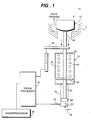
- a valve and actuator assembly 10 includes a steam turbine valve 12 engageable with an annular seat 14 (only partially shown).
- the valve 12 includes an elongated valve stem 16 which extends in an downstream direction (i.e., in the direction of flow through the seat 16) and into an actuator housing 18.
- the latter includes a relatively larger diameter spring enclosing section 20 and a relatively smaller diameter piston enclosing section 22.
- the stem 16 continues beyond flange 26 into the smaller section 22, terminating at a piston 28.
- valve 12 and piston 28 are at opposite ends of the stem 16.
- the piston 28 divides the housing section 22 into chambers 30, 32, respectively, below and above the piston.
- the lower chamber 30 (as viewed in the Figure) is pressurized via a hydraulic pressure input shown at 34, and a pressure transducer 36 communicates with chamber 30 to provide an electrical output corresponding to the pressure in that chamber.
- the spring 24 is calibrated so that movement of the valve 12 toward or away from the seat is determined by pressure within the cavity 30 below the piston 28. In this regard, there are also steam forces acting on the valve stem, which during turbine operation may be much larger than the spring force.
- LVDT linear, variable differential transformer
- the electrical outputs of the transducer 36 and stroke measuring device 38 are sent to a signal processing device 40 and then to a microprocessor (e.g., a PC) 42 which records and compares the outputs with predetermined stored values representing normal and calculated valve behavior.
- a normal valve output is plotted on a stroke vs. hydraulic pressure graph.
- the computer 42 will also monitor the rate of valve opening or closing as well as pressure difference between opening and closing at various points along the stroke, etc.
- the solid lines show a plot of hydraulic pressure vs. valve stroke for a normally operating valve, showing both opening and closing directions.
- the dotted line between the solid lines shows the calculated hydraulic pressure required to balance the spring and steam forces acting on the valve stem.
- the pressure difference Pd is a measure, for any given stroke, of frictional forces which, if excessive, will stall the valve.
- maintenance may be indicated, and the computer would display an appropriate signal to this effect on a monitor.
- readings within a larger window may be acceptable (see the dotted lines A and B in Fig. 2), but readings outside this larger window may be so abnormal as to indicate the need for immediate maintenance.
- all relevant valve information and historical data is stored in the computer memory and is used as necessary to provide the desired display output.
- the computer may also analyze readings within the window to determine the rate at which they approach the solid lines and/or the extended window defined by dotted lines A and/or B and thereby identify abnormal valve behavior indicating possible future maintenance, including projections as to when the valve will stick, etc.
- the monitoring system in accordance with this invention is not limited to use with the specific valve construction illustrated in Figure 1.
- the system may be used in connection with various rotary and linear type valves including butterfly valves, and overhead actuator-type valves.
- an overhead actuator-type valve is illustrated, using reference numerals similar to those used in Figure 1 for corresponding components, but with the prefix "1" added.
- the actuator assembly is upstream of the valve 112 (in the flow direction), but the monitoring system is otherwise similar to that described in connection with Figure 1.
- the annular seat 114, with the valve stem 116 extending in a upstream direction and into the actuator housing 118.
- the housing 118 includes a relatively larger diameter spring enclosing section 120 and a relatively smaller diameter piston enclosing section 122.
- a coil (or other suitable type) spring 124 which is supported on a flange 126 secured to the stem 116. The other end of the spring abuts against the upper wall of the housing 120, thus biasing the valve 112 in an downstream direction toward engagement with the seat 114.
- Valve stem 116 terminates at a piston 128 located in the smaller diameter housing section 122, with the piston dividing the housing section 122 into chambers 130 and 132, respectively.
- a pressure transducer 136 communicates with the chamber 132 and provides an electrical output corresponding to the pressure in that chamber.
- FIG 4 a double acting type actuator is illustrated, with hydraulic pressure applied to either side of the actuator piston 228 (via inputs 234, 234'), depending on whether the valve is opening or closing.
- reference numerals used in the figure are similar to those used for corresponding components in Figure 1, but with the prefix "2" added.
- the valve arrangement is similar to the Figure 3 embodiment, but here, two pressure transducers 236 are employed, in communication with the respective chambers 230, 232 on either side of the piston 228 to monitor the hydraulic pressure in both chambers.
- This type valve assembly eliminates the need for a spring such as 24 ( Figure 1) or 124 ( Figure 3). Otherwise, the operation of the monitoring system is as previously described.
- FIG 5 another double actuator-type valve assembly is shown, but in combination with a spring. More specifically, and using reference numerals similar to those used for corresponding components in Figures 1, 3 and 4, but with the prefix "3" added, a pair of pressure transducers 336 are located on either side of the piston 328, in communication with chambers 330 and 332, respectively. Hydraulic fluid is supplied to chamber 330, 332 by means of input 334, 334'. At the same time, a spring 324 continuously biases the piston flange 326 in a valve closing direction.
- the signal processor takes the output from the pair of pressure transducers above and below the piston and combines the pressures to calculate an effective net opening or closing pressure which would become the horizontal axis of Figure 2.
- valve constructions may benefit from the monitoring system in accordance with this invention.
- data generated in accordance with this invention may be utilized in various additional ways to monitor, record and predict valve behavior.
Landscapes
- Engineering & Computer Science (AREA)
- General Engineering & Computer Science (AREA)
- Mechanical Engineering (AREA)
- Control Of Turbines (AREA)
- Indication Of The Valve Opening Or Closing Status (AREA)
- Fluid-Driven Valves (AREA)
Applications Claiming Priority (2)
| Application Number | Priority Date | Filing Date | Title |
|---|---|---|---|
| US5474198A | 1998-04-03 | 1998-04-03 | |
| US54741 | 1998-04-03 |
Publications (2)
| Publication Number | Publication Date |
|---|---|
| EP0947901A2 true EP0947901A2 (fr) | 1999-10-06 |
| EP0947901A3 EP0947901A3 (fr) | 1999-11-17 |
Family
ID=21993205
Family Applications (1)
| Application Number | Title | Priority Date | Filing Date |
|---|---|---|---|
| EP99302523A Withdrawn EP0947901A3 (fr) | 1998-04-03 | 1999-03-31 | Système de surveillance pour la maintenance des vannes d'une turbine à vapeur |
Country Status (3)
| Country | Link |
|---|---|
| EP (1) | EP0947901A3 (fr) |
| JP (1) | JPH11315955A (fr) |
| KR (1) | KR19990082805A (fr) |
Cited By (11)
| Publication number | Priority date | Publication date | Assignee | Title |
|---|---|---|---|---|
| DE19917737A1 (de) * | 1999-04-20 | 2000-11-23 | Arca Regler Gmbh | Stelleinrichtung, insbesondere Regelventil |
| WO2002017028A1 (fr) * | 2000-08-22 | 2002-02-28 | Fisher Controls International, Inc. | Methode de detection de l'usure d'un couvercle de vanne |
| WO2003053539A1 (fr) * | 2001-12-20 | 2003-07-03 | Goyen Controls Co. Pty Limited | Nettoyage d'elements filtrants par injection d'air comprime a contre-courant |
| EP1443219A1 (fr) * | 2003-01-30 | 2004-08-04 | bar-pneumatische Steuerungssysteme GmbH | Méthode et dispositif pour tester un actionneur pneumatique |
| WO2005112551A3 (fr) * | 2004-05-21 | 2006-03-16 | Hansung Engineering Co Ltd | Procede de compensation d'une ombre partielle dans un systeme d'energie photovoltaique |
| EP1965113A1 (fr) * | 2007-02-28 | 2008-09-03 | Honeywell International Inc. | Ensemble actionneur doté d'un joint hermétique et d'un coupleur rotationnel magnétique |
| CN100507324C (zh) * | 2006-03-29 | 2009-07-01 | 宝山钢铁股份有限公司 | 大流量比例控制水阀 |
| WO2020214159A1 (fr) * | 2019-04-17 | 2020-10-22 | Siemens Energy, Inc. | Système et procédé de contrôle de vanne |
| CN112041601A (zh) * | 2018-05-08 | 2020-12-04 | 阿法拉伐股份有限公司 | 阀控制器和控制阀的方法 |
| US20210222794A1 (en) * | 2020-01-17 | 2021-07-22 | Fisher Controls International Llc | Method and System for Executing Online Tests of Valve Seating Integrity for Control Valves |
| US12123517B2 (en) | 2017-11-29 | 2024-10-22 | Fujikin Incorporated | Valve, abnormality diagnosis method of valve |
Families Citing this family (8)
| Publication number | Priority date | Publication date | Assignee | Title |
|---|---|---|---|---|
| US7886766B2 (en) * | 2006-12-27 | 2011-02-15 | Eltav Wireless Monitoring Ltd. | Device and system for monitoring valves |
| JP5501172B2 (ja) * | 2010-09-13 | 2014-05-21 | リンナイ株式会社 | 止水装置 |
| KR101439061B1 (ko) * | 2013-11-05 | 2014-09-05 | 한전케이피에스 주식회사 | 공기구동 밸브 구동기의 스프링와셔 교정 장치 |
| CN104214415B (zh) * | 2014-08-31 | 2016-09-14 | 贵州电力试验研究院 | 一种汽轮机高压缸进汽调节阀开度信号软测量方法 |
| JP6564213B2 (ja) * | 2015-03-25 | 2019-08-21 | 株式会社フジキン | 流体制御装置 |
| US20180058255A1 (en) * | 2016-08-31 | 2018-03-01 | General Electric Technology Gmbh | Guide Condition Assessment Module For A Valve And Actuator Monitoring System |
| JP6845704B2 (ja) * | 2017-02-13 | 2021-03-24 | 株式会社東芝 | 油圧駆動弁監視装置、油圧駆動弁監視方法、および制御システム |
| JP6454815B1 (ja) * | 2018-10-01 | 2019-01-16 | 東北発電工業株式会社 | 測定方法、及び、測定補助具 |
Family Cites Families (8)
| Publication number | Priority date | Publication date | Assignee | Title |
|---|---|---|---|---|
| US4368520A (en) * | 1980-09-29 | 1983-01-11 | Westinghouse Electric Corp. | Steam turbine generator control system |
| GB8620357D0 (en) * | 1986-08-21 | 1986-10-01 | Apv Int Ltd | Flow control valve |
| KR890007306A (ko) * | 1987-10-30 | 1989-06-19 | 제트.엘.더머 | 온라인 밸브 진단 감시 시스템 |
| US4976144A (en) * | 1988-08-25 | 1990-12-11 | Fisher Controls International, Inc. | Diagnostic apparatus and method for fluid control valves |
| US5253185A (en) * | 1991-01-30 | 1993-10-12 | Combustion Engineering, Inc. | Valve diagnostic system including auxiliary transducer box |
| DE4218320A1 (de) * | 1992-06-03 | 1993-12-09 | Siemens Ag | Verfahren und Einrichtung zur Prüfung einer durch ein Medium angetriebenen Armatur |
| IT1265319B1 (it) * | 1993-12-22 | 1996-10-31 | Nuovo Pignone Spa | Sistema perfezionato di comando dell'attuatore di una valvola pneumatica |
| JP3182717B2 (ja) * | 1996-06-06 | 2001-07-03 | 株式会社山武 | 調節弁異常検出方法および検出装置 |
-
1999
- 1999-03-31 JP JP11090409A patent/JPH11315955A/ja not_active Withdrawn
- 1999-03-31 EP EP99302523A patent/EP0947901A3/fr not_active Withdrawn
- 1999-03-31 KR KR1019990011157A patent/KR19990082805A/ko not_active Withdrawn
Cited By (17)
| Publication number | Priority date | Publication date | Assignee | Title |
|---|---|---|---|---|
| DE19917737A1 (de) * | 1999-04-20 | 2000-11-23 | Arca Regler Gmbh | Stelleinrichtung, insbesondere Regelventil |
| WO2002017028A1 (fr) * | 2000-08-22 | 2002-02-28 | Fisher Controls International, Inc. | Methode de detection de l'usure d'un couvercle de vanne |
| WO2003053539A1 (fr) * | 2001-12-20 | 2003-07-03 | Goyen Controls Co. Pty Limited | Nettoyage d'elements filtrants par injection d'air comprime a contre-courant |
| US7517376B2 (en) | 2001-12-20 | 2009-04-14 | Goyen Controls Co. Pty. Ltd. | Reverse pulse cleaning of filter elements |
| EP1443219A1 (fr) * | 2003-01-30 | 2004-08-04 | bar-pneumatische Steuerungssysteme GmbH | Méthode et dispositif pour tester un actionneur pneumatique |
| WO2005112551A3 (fr) * | 2004-05-21 | 2006-03-16 | Hansung Engineering Co Ltd | Procede de compensation d'une ombre partielle dans un systeme d'energie photovoltaique |
| CN100507324C (zh) * | 2006-03-29 | 2009-07-01 | 宝山钢铁股份有限公司 | 大流量比例控制水阀 |
| EP1965113A1 (fr) * | 2007-02-28 | 2008-09-03 | Honeywell International Inc. | Ensemble actionneur doté d'un joint hermétique et d'un coupleur rotationnel magnétique |
| US12123517B2 (en) | 2017-11-29 | 2024-10-22 | Fujikin Incorporated | Valve, abnormality diagnosis method of valve |
| US11725677B2 (en) | 2018-05-08 | 2023-08-15 | Alfa Laval Corporate Ab | Valve controller and method of controlling a valve |
| CN112041601A (zh) * | 2018-05-08 | 2020-12-04 | 阿法拉伐股份有限公司 | 阀控制器和控制阀的方法 |
| WO2020214159A1 (fr) * | 2019-04-17 | 2020-10-22 | Siemens Energy, Inc. | Système et procédé de contrôle de vanne |
| US20210222794A1 (en) * | 2020-01-17 | 2021-07-22 | Fisher Controls International Llc | Method and System for Executing Online Tests of Valve Seating Integrity for Control Valves |
| CN113217702A (zh) * | 2020-01-17 | 2021-08-06 | 费希尔控制产品国际有限公司 | 用于执行控制阀的阀落座完整性的在线测试的方法和系统 |
| US11835152B2 (en) * | 2020-01-17 | 2023-12-05 | Fisher Controls International Llc | Method and system for executing online tests of valve seating integrity for control valves |
| US12352368B2 (en) | 2020-01-17 | 2025-07-08 | Fisher Controls International Llc | Method and system for executing online tests of valve seating integrity for control valves |
| CN113217702B (zh) * | 2020-01-17 | 2026-03-06 | 费希尔控制产品国际有限公司 | 用于执行控制阀的阀落座完整性的在线测试的方法和系统 |
Also Published As
| Publication number | Publication date |
|---|---|
| JPH11315955A (ja) | 1999-11-16 |
| KR19990082805A (ko) | 1999-11-25 |
| EP0947901A3 (fr) | 1999-11-17 |
Similar Documents
| Publication | Publication Date | Title |
|---|---|---|
| EP0947901A2 (fr) | Système de surveillance pour la maintenance des vannes d'une turbine à vapeur | |
| EP0708389B1 (fr) | Méthode et appareil pour détecter un défaut d'un dispositif de vanne de commande dans une boucle de régulation | |
| EP3051285B1 (fr) | Système de contrôle de soupape de commande | |
| EP1508736B1 (fr) | Procédé de diagnostic d'un système cyclique | |
| US5524484A (en) | Solenoid operated valve diagnostic system | |
| JP5015396B2 (ja) | プロセス制御ループパラメータの推定値の統計的に決定する方法 | |
| US6240789B1 (en) | Permanently instrumented actuated valve assembly, with internally-gauged, permanently instrumented shaft | |
| CN103180647B (zh) | 用于提升阀的诊断方法和用于执行所述方法的测量装置 | |
| US5487302A (en) | Method and system for measuring gate valve clearances and seating force | |
| JPH09502292A (ja) | 圧力フィードバック、動的補正、および診断機能を備えたバルブ位置制御装置 | |
| CN113464711B (zh) | 一种基于振动测量技术的阀门内漏监测系统及方法 | |
| JP7356267B2 (ja) | 異常検知装置、異常検知方法及びプログラム | |
| JP2012508857A (ja) | 故障様式および健全状態の徴候としてバルブの可動コアのストローク、速度および/または加速度を決定するためのセンサを有するソレノイドバルブ | |
| JP2009526332A (ja) | 流体調節のためのシステムおよび方法 | |
| JP6823089B2 (ja) | ターボ機械の非回転部品を監視するための方法およびシステム | |
| US8147211B2 (en) | Method and system for monitoring a reciprocating compressor valve | |
| KR20050078804A (ko) | 공기구동식 밸브시스템의 진단장치 | |
| JP2011080805A (ja) | 弁装置の健全性監視評価システム及び方法 | |
| WO2007107725A1 (fr) | Détermination par capteur de l'état d'une soupape de sûreté | |
| US6549856B2 (en) | Fluid contaminant sensor | |
| WO2013048266A1 (fr) | Système et procédé de surveillance d'efficacité polytropique d'un compresseur de gaz de charge | |
| Sharif et al. | Sensor-based performance monitoring of a control valve unit | |
| JP3188267B2 (ja) | モーター駆動弁システムの状態モニター方法 | |
| Charbonneau | Innovations in Non-Intrusive Testing and Trending of Motor Operated Valves and Check Valves | |
| Ghosh et al. | Prognostics & health management of swing type check valves |
Legal Events
| Date | Code | Title | Description |
|---|---|---|---|
| PUAI | Public reference made under article 153(3) epc to a published international application that has entered the european phase |
Free format text: ORIGINAL CODE: 0009012 |
|
| PUAL | Search report despatched |
Free format text: ORIGINAL CODE: 0009013 |
|
| AK | Designated contracting states |
Kind code of ref document: A2 Designated state(s): DE FR GB |
|
| AX | Request for extension of the european patent |
Free format text: AL;LT;LV;MK;RO;SI |
|
| AK | Designated contracting states |
Kind code of ref document: A3 Designated state(s): AT BE CH CY DE DK ES FI FR GB GR IE IT LI LU MC NL PT SE |
|
| AX | Request for extension of the european patent |
Free format text: AL;LT;LV;MK;RO;SI |
|
| RIC1 | Information provided on ipc code assigned before grant |
Free format text: 6G 05B 23/02 A |
|
| 17P | Request for examination filed |
Effective date: 20000517 |
|
| AKX | Designation fees paid |
Free format text: DE FR GB |
|
| 17Q | First examination report despatched |
Effective date: 20030211 |
|
| STAA | Information on the status of an ep patent application or granted ep patent |
Free format text: STATUS: THE APPLICATION IS DEEMED TO BE WITHDRAWN |
|
| 18D | Application deemed to be withdrawn |
Effective date: 20030624 |