EP0947947A2 - Robustes Verfahren zur Ermittlung der Lagen von Registrierungsmarken - Google Patents
Robustes Verfahren zur Ermittlung der Lagen von Registrierungsmarken Download PDFInfo
- Publication number
- EP0947947A2 EP0947947A2 EP99302194A EP99302194A EP0947947A2 EP 0947947 A2 EP0947947 A2 EP 0947947A2 EP 99302194 A EP99302194 A EP 99302194A EP 99302194 A EP99302194 A EP 99302194A EP 0947947 A2 EP0947947 A2 EP 0947947A2
- Authority
- EP
- European Patent Office
- Prior art keywords
- marker
- image
- pattern
- document
- variance
- Prior art date
- Legal status (The legal status is an assumption and is not a legal conclusion. Google has not performed a legal analysis and makes no representation as to the accuracy of the status listed.)
- Granted
Links
Images


Classifications
-
- G—PHYSICS
- G06—COMPUTING OR CALCULATING; COUNTING
- G06V—IMAGE OR VIDEO RECOGNITION OR UNDERSTANDING
- G06V10/00—Arrangements for image or video recognition or understanding
- G06V10/40—Extraction of image or video features
- G06V10/50—Extraction of image or video features by performing operations within image blocks; by using histograms, e.g. histogram of oriented gradients [HoG]; by summing image-intensity values; Projection analysis
- G06V10/507—Summing image-intensity values; Histogram projection analysis
-
- G—PHYSICS
- G06—COMPUTING OR CALCULATING; COUNTING
- G06V—IMAGE OR VIDEO RECOGNITION OR UNDERSTANDING
- G06V10/00—Arrangements for image or video recognition or understanding
- G06V10/40—Extraction of image or video features
- G06V10/42—Global feature extraction by analysis of the whole pattern, e.g. using frequency domain transformations or autocorrelation
- G06V10/421—Global feature extraction by analysis of the whole pattern, e.g. using frequency domain transformations or autocorrelation by analysing segments intersecting the pattern
Definitions
- the present invention is related to image processing and pattern recognition and, more particularly, to assessing the image quality produced by an electronic scanning device by using test targets containing special image patterns.
- Image quality assessment and adjustment is often done in an image processing system (such as a photocopier, electronic scanner, digital camera, or video camera) by capturing the image of a test target with known physical attributes.
- the measured attributes are compared to the physical measurements to provide a characterization of the system.
- a sequence of gray patches, increasing from light to dark can be produced with known darknesses (optical densities) by measuring the ratio of impinging light to the amount of reflected light under controlled conditions.
- the step-wedge is then captured with an electronic imaging device so that the image is represented as an array of pixel values.
- Each patch represents a different optical density and maps to a "digital count" in the imaging device.
- a mapping can thus be inferred from true optical density to digital counts in the electronic device.
- This mapping called a tone reproduction curve (TRC)
- TRC tone reproduction curve
- An automatic means of detecting the location of patches in the array of pixels in electronic device (or computer memory) is needed to conveniently compute the mapping.
- One method is to put distinguishing markers in the corners of the test target and measure the positions of the patches relative to the markers.
- a calibration program as executed by a central processing unit would analyze the array to detect the markers. By knowing the physical distance among the markers and computing the distance between the detected markers in the image, a scale factor can be computed which allows the positions of the patches in the array to be computed.
- Automatic calibration is desirable in a commercial product where the na ⁇ ve user is relieved of the task of calibration. Indeed, a set of instructions can be provided to the user to image a test target and press a button and then continue with image capture.
- the entire test target is rendered, printed in halftones and scanned in. Measurements from original patches are compared with scanned halftoned patches. To make this process automatic for a naive user, the registration markers must be detected even though they have suffered serious degradation through scanning, halftoning, printing and rescanning.
- Figure 2 shows an example of a test target.
- the two markers at the top are to be detected.
- Calibration algorithms use the detected positions to then compute the positions of the patches in the image array.
- the same test target may be scanned in a plurality of resolutions, including anisotropic aspect ratios (e.g. 400 by 600 dots per inch), as well as being subject to extreme distortions by the imaging system.
- anisotropic aspect ratios e.g. 400 by 600 dots per inch
- an algorithm to detect the markers must be robust against these distortions (halftoning, low contrast, etc).
- the present invention is designed and proven to be robust against a variety of distortions.
- US Patent 5,198,907 provides a means for target registration using an inverted 'L'-shaped figure, called “guide bars”.
- Guide bars are detected using edge detection and following. The algorithm starts at the upper left corner and uses differences in "exposure” to detect the edge. It then follows edges to find bard with the correct width and height.
- the guide bars are long relative to the captured area and in horizontal and vertical directions. The dimensions (lengths and widths) must be known beforehand to allow detection. These constraints preclude marker identification under the extreme distortions this invention overcomes.
- US Patent 5,642,202 provides a means for calibrating a printer. Using registration marks, the original and scanned, printed version can be registered and compared to generate calibration data. Registration marks are three collinear triangles having designated non-collinear "apexes" at known positions which are used to compute the registration transformation from the scanned image to the original. These triangles are detected using black-to-white and white-to-black transitions along horizontal scans. This method is not robust to halftoning (dithering or error diffusion) nor can there can be any image content or noise between the triangles because the algorithm looks for exactly 6 transitions. Nor can there be large amounts of document skew that would make it impossible to find the six transitions.
- US Patent No. 4,153,897 to Yasuda et al. discloses a pattern recognition system where similarities between unknown and standard patterns are identified. Similarities are detected at first in respective shifting conditions where the unknown and standard patterns are relatively shifted from each other over the first limited extent, including the condition without shift. The maximum value of these similarities is then detected. The similarities are further detected in respective shifting conditions where the unknown and standard patterns are relatively shifted from each other over the second extent larger than the first limited extent, when the shifting condition which gave the maximum value is that without relative shift.
- US Patent No. 5216724 to Suzuki et al. discloses an apparatus for image reading or processing that can precisely identify a particular pattern, such as bank notes or securities.
- a detecting unit detects positional information of an original image and a discriminating unit extracts pattern data from a certain part of the original image to discriminate whether the original image is the predetermined image based on the similarity between the pattern data and the predetermined pattern.
- US Patent No. 5,291,243 Heckman et al. discloses a system for printing security documents which have copy detection or tamper resistance in plural colors with a single pass electronic printer.
- a validating signature has two intermixed color halftone patterns with halftone density gradients varying across the signature in opposite directions, but different from the background.
- a method for detecting the presence and orientation of a predefined marker on a document comprises capturing a document having at least one test marker;
- test target when the test target is captured, it is represented as a gray-scale image in device or computer memory where each picture element (pixel) is represented by a value between 0 and 255, inclusive, stored in a byte.
- each picture element pixel
- black is represented by 0
- white is represented by 255. This assumption is not necessary for the invention, but simplifies this exposition.
- image not so represented means well-known in the prior art could be used to convert it to this representation.
- the first step is to threshold the image using a value T to produce a binary representation by assigning those pixels with a value less than T the value 0 and those greater than or equal to T, the value 1.
- the next step is to determine the eight (or four)-connected components in the binary image.
- the markers will be among these.
- Finding connected components in a binary image is well-known in the prior art.
- the preferred embodiment converts the binary image to a runlength representation, builds a line adjacency graph, and then finds connected components in this graph [T. Pavlidis, Algorithms for Graphics and Image Processing, 1981 , Computer Science Press, Rockville, MD].
- each is inspected to determine whether or not it is a marker or not.
- the centroid of the markers are reported to the calibration process, which has stored the positions of the patches relative to these markers.
- the identification method in a scanner production environment, where testing must be done quickly and reliably for each machine, is the subject of this invention.
- a test target image such as the one in Figure 2 is captured as a raster scan comprised by an array of values in computer memory where each of which is a value between 0 and 255.
- the value 0 represents black, or minimum reflectance
- 255 represents white, or maximum reflectance.
- the image may be obtained by any electronic capture device, typically, but not limited to a document scanner, an electronic (digital) still image camera, or video camera.
- any image representation amenable to binary representation can also be processed. All that is required is that the shapes of the symbols in the image be represented in a binary way.
- the image is a color image with each pixel represented as a triplet of red, green, and blue reflectances
- procedures known in the prior art can be used to convert the color image to an "intensity" image.
- any one or all of the red, green, and blue channels can be processed.
- the marker need not be black on white, but must have a spectral reflectance that is distinguishable from the spectral reflectance of the background.
- the image is thresholded.
- Other values such as 127 or 129 could be used.
- the pixel value is great than or equal to T, the pixel value is labeled white and black otherwise.
- the resulting binary image captures the essential shape of the marker (and content in the image). As noted above, black and white serve as labels to distinguish the marker from the back ground based upon some decision procedure, whether it be a simply threshold, a sophisticated adaptive binarization algorithm or analysis of the spectral reflectances of the image.
- Figure 3 is a depiction of a "perfect” or “ideal” "X” marker.
- Figure 4 shows the same "X", scanned anisotropically, particularly with a higher resolution horizontally than vertically, thereby providing the distorted appearance.
- the inventive method is designated to be robust in the face of such distortions.
- the next step is to convert the binary image into 8-connected (or alternatively 4-connected) contiguous regions of black. These regions are called connected components and efficient methods for finding them are well-known in the prior art.
- Each component is represented as a collection of black horizontal runlengths with starting and end coordinates, this being one of the many representations of a connected component well-known in the prior art.
- Each has an associated data structure which serves to store features measured for each connected component. For each component, the following are computed.
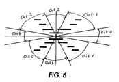
- the first feature is the centroid also called the center of gravity and the central first moment. Calculation of the centroid is well-known in the prior art. From the centroid, the plane is divided into four quadrants as depicted in Figure 5.
- ne For each quadrant, labeled ne, nw, se, and sw , a count is tallied of the number of runlengths completely contained within each quadrant. The average and sum of squared errors is computed, designated mean and variance, respectively. If the shape is an 'X', one would expect the mean to be less than but near 1.0 and the variance to be small.
- oct0 (345, 15]
- oct1 (15, 75]
- oct2 (75, 105]
- oct3 (105, 165]
- oct4 (165, 195]
- oct5 (195, 255]
- oct6 (255, 285]
- oct7 (285, 345].
- a tally is made of the number of horizontal runlengths that have midpoints in that octant. To increase detection accuracy, only runlengths with a midpoint a certain distance from the centroid are tallied.
- the calibration process having the coordinates of various patches relative to the markers along with the captured image resolution, can find the patches on the image and register them to the known data for the patches on the test image original.
- the scanned image data obtained from these "patches” are can be processed by a microprocessor using software to determine the scanner's modulation transfer function (MTF), pixel-to-pixel uniformity, tone reproduction curve (TRC) and random noise. Patch locations relative to special markers are known to the analysis software.
- MTF modulation transfer function
- TRC tone reproduction curve
- Patch locations relative to special markers are known to the analysis software.
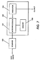
- a scanning apparatus 102 would capture a document image that would include such markers.
- a microprocessor 101 would receive the document image and conduct the analysis given the software accessed from memory 103. Marker detection, or failure of detection would then be conveyed electronically to the user through signaling means 104 such as a CRT.
Landscapes
- Engineering & Computer Science (AREA)
- Physics & Mathematics (AREA)
- General Physics & Mathematics (AREA)
- Multimedia (AREA)
- Theoretical Computer Science (AREA)
- Computer Vision & Pattern Recognition (AREA)
- Image Analysis (AREA)
- Facsimile Scanning Arrangements (AREA)
- Accessory Devices And Overall Control Thereof (AREA)
Applications Claiming Priority (2)
| Application Number | Priority Date | Filing Date | Title |
|---|---|---|---|
| US09/050,213 US6141464A (en) | 1998-03-30 | 1998-03-30 | Robust method for finding registration marker positions |
| US50213 | 1998-03-30 |
Publications (3)
| Publication Number | Publication Date |
|---|---|
| EP0947947A2 true EP0947947A2 (de) | 1999-10-06 |
| EP0947947A3 EP0947947A3 (de) | 2000-09-20 |
| EP0947947B1 EP0947947B1 (de) | 2004-06-30 |
Family
ID=21963984
Family Applications (1)
| Application Number | Title | Priority Date | Filing Date |
|---|---|---|---|
| EP99302194A Expired - Lifetime EP0947947B1 (de) | 1998-03-30 | 1999-03-22 | Robustes Verfahren zur Ermittlung der Lagen von Registrierungsmarken |
Country Status (4)
| Country | Link |
|---|---|
| US (1) | US6141464A (de) |
| EP (1) | EP0947947B1 (de) |
| JP (1) | JP2000082144A (de) |
| DE (1) | DE69918349T2 (de) |
Cited By (3)
| Publication number | Priority date | Publication date | Assignee | Title |
|---|---|---|---|---|
| EP1274224A3 (de) * | 2001-06-28 | 2004-11-17 | Nokia Corporation | Bildverbesserungsverfahren und -vorrichtung |
| WO2014080294A3 (en) * | 2012-11-12 | 2014-11-27 | Vistaprint Schweiz Gmbh | Method and system for detecting and removing printer control marks from rasterized image for placement in image container of document template |
| CN105528784A (zh) * | 2015-12-02 | 2016-04-27 | 沈阳东软医疗系统有限公司 | 一种前景背景分割的方法和装置 |
Families Citing this family (25)
| Publication number | Priority date | Publication date | Assignee | Title |
|---|---|---|---|---|
| US6442497B1 (en) * | 2000-04-14 | 2002-08-27 | Eastman Kodak Company | Calibration method and strip for film scanners in digital photofinishing systems |
| US7023578B2 (en) * | 2001-01-23 | 2006-04-04 | Xerox Corporation | Printer image processing system with customized tone reproduction curves |
| US6603882B2 (en) * | 2001-04-12 | 2003-08-05 | Seho Oh | Automatic template generation and searching method |
| US6842538B2 (en) * | 2001-03-23 | 2005-01-11 | Shih-Jong J. Lee | Automatic detection of alignment or registration marks |
| US6507675B1 (en) | 2001-03-23 | 2003-01-14 | Shih-Jong J. Lee | Structure-guided automatic learning for image feature enhancement |
| US6667756B2 (en) * | 2001-08-27 | 2003-12-23 | Xerox Corporation | Method of shifting an image or paper to reduce show through in duplex printing |
| US6763199B2 (en) | 2002-01-16 | 2004-07-13 | Xerox Corporation | Systems and methods for one-step setup for image on paper registration |
| US7167574B2 (en) * | 2002-03-14 | 2007-01-23 | Seiko Epson Corporation | Method and apparatus for content-based image copy detection |
| US6903758B1 (en) | 2002-12-17 | 2005-06-07 | Xerox Corporation | Method for maintaining image squareness and image on image registration |
| US7039348B2 (en) * | 2002-12-17 | 2006-05-02 | Xerox Corporation | Method for maintaining image on image and image on paper registration |
| US7532804B2 (en) * | 2003-06-23 | 2009-05-12 | Seiko Epson Corporation | Method and apparatus for video copy detection |
| US7206008B2 (en) * | 2004-10-28 | 2007-04-17 | Xerox Corporation | Method for calibrating color in a printing device |
| US7486827B2 (en) * | 2005-01-21 | 2009-02-03 | Seiko Epson Corporation | Efficient and robust algorithm for video sequence matching |
| US7420719B2 (en) * | 2005-06-30 | 2008-09-02 | Xerox Corporation | Skew correction |
| DE102005035678A1 (de) * | 2005-07-27 | 2007-02-01 | Adc Automotive Distance Control Systems Gmbh | Vorrichtung zur Kalibrierung einer Kamera |
| JP4847302B2 (ja) * | 2005-12-01 | 2011-12-28 | 富士フイルム株式会社 | 記録媒体搬送量測定方法及びインクジェット記録装置 |
| KR101158005B1 (ko) * | 2007-03-06 | 2012-06-25 | 삼성전자주식회사 | 인쇄품질 평가지표 산출 방법 및 장치 |
| US8154771B2 (en) * | 2008-01-29 | 2012-04-10 | K-Nfb Reading Technology, Inc. | Training a user on an accessiblity device |
| US8249343B2 (en) | 2008-10-15 | 2012-08-21 | Xerox Corporation | Representing documents with runlength histograms |
| US8305642B2 (en) * | 2008-12-19 | 2012-11-06 | Xerox Corporation | Method and system for correlating of uniformity compensations across halftone screens |
| WO2012063107A1 (en) * | 2010-11-08 | 2012-05-18 | Manipal Institute Of Technology | Automated tuberculosis screening |
| DE102011084829B4 (de) | 2011-10-19 | 2016-07-14 | Carl Zeiss Ag | Mikroskopie mehrerer Proben mit optischer Mikroskopie und Teilchenstrahlmikroskopie |
| JP7365986B2 (ja) * | 2020-09-25 | 2023-10-20 | Kddi株式会社 | カメラキャリブレーション装置、方法およびプログラム |
| CN116109577A (zh) * | 2022-12-27 | 2023-05-12 | 无锡群欢包装材料有限公司 | 一种印刷标签缺陷检测系统及方法 |
| CN119090856A (zh) * | 2024-09-06 | 2024-12-06 | 常州市新创智能科技有限公司 | 碳纤维丝束接头检测方法、装置、设备及介质 |
Family Cites Families (10)
| Publication number | Priority date | Publication date | Assignee | Title |
|---|---|---|---|---|
| JPS5313840A (en) * | 1976-07-23 | 1978-02-07 | Hitachi Ltd | Analogy calculator |
| US4989257A (en) * | 1987-03-13 | 1991-01-29 | Gtx Corporation | Method and apparatus for generating size and orientation invariant shape features |
| DE69023782T2 (de) * | 1989-02-10 | 1996-06-13 | Canon Kk | Gerät zum Lesen oder Verarbeiten eines Bildes. |
| EP0405400A3 (en) * | 1989-06-30 | 1992-09-02 | Mita Industrial Co., Ltd. | Image distinguishing device |
| US5267328A (en) * | 1990-01-22 | 1993-11-30 | Gouge James O | Method for selecting distinctive pattern information from a pixel generated image |
| US5054094A (en) * | 1990-05-07 | 1991-10-01 | Eastman Kodak Company | Rotationally impervious feature extraction for optical character recognition |
| US5198907A (en) * | 1991-08-23 | 1993-03-30 | Eastman Kodak Company | Method and appratus for automatically locating predefined exposure areas in a scanned image |
| DE69228741T2 (de) * | 1991-10-02 | 1999-09-02 | Fujitsu Ltd. | Verfahren zur bestimmung der lokalen orientierung eines kontursegmentes und zur bestimmung von linien und ecken |
| US5291243A (en) * | 1993-02-05 | 1994-03-01 | Xerox Corporation | System for electronically printing plural-color tamper-resistant documents |
| US5642202A (en) * | 1994-12-01 | 1997-06-24 | Xerox Corporation | Scan image target locator system for calibrating a printing system |
-
1998
- 1998-03-30 US US09/050,213 patent/US6141464A/en not_active Expired - Lifetime
-
1999
- 1999-03-22 DE DE69918349T patent/DE69918349T2/de not_active Expired - Lifetime
- 1999-03-22 EP EP99302194A patent/EP0947947B1/de not_active Expired - Lifetime
- 1999-03-26 JP JP11082692A patent/JP2000082144A/ja active Pending
Cited By (6)
| Publication number | Priority date | Publication date | Assignee | Title |
|---|---|---|---|---|
| EP1274224A3 (de) * | 2001-06-28 | 2004-11-17 | Nokia Corporation | Bildverbesserungsverfahren und -vorrichtung |
| US7426316B2 (en) | 2001-06-28 | 2008-09-16 | Nokia Corporation | Method and apparatus for image improvement |
| US8103123B2 (en) | 2001-06-28 | 2012-01-24 | Nokia Corporation | Method and apparatus for image improvement |
| WO2014080294A3 (en) * | 2012-11-12 | 2014-11-27 | Vistaprint Schweiz Gmbh | Method and system for detecting and removing printer control marks from rasterized image for placement in image container of document template |
| CN105528784A (zh) * | 2015-12-02 | 2016-04-27 | 沈阳东软医疗系统有限公司 | 一种前景背景分割的方法和装置 |
| CN105528784B (zh) * | 2015-12-02 | 2019-01-25 | 沈阳东软医疗系统有限公司 | 一种前景背景分割的方法和装置 |
Also Published As
| Publication number | Publication date |
|---|---|
| US6141464A (en) | 2000-10-31 |
| JP2000082144A (ja) | 2000-03-21 |
| DE69918349T2 (de) | 2005-07-14 |
| DE69918349D1 (de) | 2004-08-05 |
| EP0947947B1 (de) | 2004-06-30 |
| EP0947947A3 (de) | 2000-09-20 |
Similar Documents
| Publication | Publication Date | Title |
|---|---|---|
| EP0947947B1 (de) | Robustes Verfahren zur Ermittlung der Lagen von Registrierungsmarken | |
| EP1014677B1 (de) | Entfernung parasitärer Signale für schräglagenkorrigierte Bilder | |
| CN117541588B (zh) | 一种纸制品的印刷缺陷检测方法 | |
| CN102422328B (zh) | 用于钞票检测器装置的方法和钞票检测器装置 | |
| US6026186A (en) | Line and curve detection using local information | |
| US8139117B2 (en) | Image quality analysis with test pattern | |
| US6970606B2 (en) | Automatic image quality evaluation and correction technique for digitized and thresholded document images | |
| US8331670B2 (en) | Method of detection document alteration by comparing characters using shape features of characters | |
| JP3545506B2 (ja) | 特定色領域抽出方式および特定色領域除去方式 | |
| JPH0869534A (ja) | 画像品質の検知方法及び装置 | |
| KR100542365B1 (ko) | 영상 화질 개선 장치 및 그 방법 | |
| CN115423771B (zh) | 基于特征非一致性的准动态镭射防伪标签识别方法 | |
| CN115170525B (zh) | 一种图像差异检测方法及装置 | |
| CA2281113C (en) | Automatic inspection of print quality using an elastic model | |
| US20040131242A1 (en) | Monitoring method | |
| JP2021039734A (ja) | 光学コードのモジュールサイズの特定 | |
| EP0505729B1 (de) | Bildbinarisierungssystem | |
| KR100726473B1 (ko) | 이미지 분별 장치 및 그 방법 | |
| CN112215319B (zh) | 颜色标记特征图形的二维码及其识别方法 | |
| CN120088794B (zh) | 一种档案图像质量检测方法 | |
| JPH10214327A (ja) | 画像を用いた表面欠陥検出方法 | |
| JP3823379B2 (ja) | 画像処理方法 | |
| Mettanen et al. | Alignment and statistical analysis of 2D small-scale paper property maps | |
| AU2008261177B2 (en) | Target feature detection system | |
| JPH05172535A (ja) | ピーク点検出方法及びキャリブレーション方法 |
Legal Events
| Date | Code | Title | Description |
|---|---|---|---|
| PUAI | Public reference made under article 153(3) epc to a published international application that has entered the european phase |
Free format text: ORIGINAL CODE: 0009012 |
|
| AK | Designated contracting states |
Kind code of ref document: A2 Designated state(s): DE FR GB |
|
| AX | Request for extension of the european patent |
Free format text: AL;LT;LV;MK;RO;SI |
|
| PUAL | Search report despatched |
Free format text: ORIGINAL CODE: 0009013 |
|
| AK | Designated contracting states |
Kind code of ref document: A3 Designated state(s): AT BE CH CY DE DK ES FI FR GB GR IE IT LI LU MC NL PT SE |
|
| AX | Request for extension of the european patent |
Free format text: AL;LT;LV;MK;RO;SI |
|
| RIC1 | Information provided on ipc code assigned before grant |
Free format text: 7G 06K 9/46 A, 7G 06K 9/32 B |
|
| 17P | Request for examination filed |
Effective date: 20010320 |
|
| AKX | Designation fees paid |
Free format text: DE FR GB |
|
| 17Q | First examination report despatched |
Effective date: 20021129 |
|
| GRAP | Despatch of communication of intention to grant a patent |
Free format text: ORIGINAL CODE: EPIDOSNIGR1 |
|
| GRAS | Grant fee paid |
Free format text: ORIGINAL CODE: EPIDOSNIGR3 |
|
| GRAA | (expected) grant |
Free format text: ORIGINAL CODE: 0009210 |
|
| AK | Designated contracting states |
Kind code of ref document: B1 Designated state(s): DE FR GB |
|
| REG | Reference to a national code |
Ref country code: GB Ref legal event code: FG4D |
|
| REF | Corresponds to: |
Ref document number: 69918349 Country of ref document: DE Date of ref document: 20040805 Kind code of ref document: P |
|
| REG | Reference to a national code |
Ref country code: GB Ref legal event code: 746 Effective date: 20041130 |
|
| ET | Fr: translation filed | ||
| REG | Reference to a national code |
Ref country code: FR Ref legal event code: D6 |
|
| PLBE | No opposition filed within time limit |
Free format text: ORIGINAL CODE: 0009261 |
|
| STAA | Information on the status of an ep patent application or granted ep patent |
Free format text: STATUS: NO OPPOSITION FILED WITHIN TIME LIMIT |
|
| 26N | No opposition filed |
Effective date: 20050331 |
|
| REG | Reference to a national code |
Ref country code: FR Ref legal event code: PLFP Year of fee payment: 17 |
|
| PGFP | Annual fee paid to national office [announced via postgrant information from national office to epo] |
Ref country code: DE Payment date: 20150219 Year of fee payment: 17 |
|
| PGFP | Annual fee paid to national office [announced via postgrant information from national office to epo] |
Ref country code: FR Payment date: 20150319 Year of fee payment: 17 Ref country code: GB Payment date: 20150226 Year of fee payment: 17 |
|
| REG | Reference to a national code |
Ref country code: DE Ref legal event code: R119 Ref document number: 69918349 Country of ref document: DE |
|
| GBPC | Gb: european patent ceased through non-payment of renewal fee |
Effective date: 20160322 |
|
| REG | Reference to a national code |
Ref country code: FR Ref legal event code: ST Effective date: 20161130 |
|
| PG25 | Lapsed in a contracting state [announced via postgrant information from national office to epo] |
Ref country code: DE Free format text: LAPSE BECAUSE OF NON-PAYMENT OF DUE FEES Effective date: 20161001 Ref country code: GB Free format text: LAPSE BECAUSE OF NON-PAYMENT OF DUE FEES Effective date: 20160322 Ref country code: FR Free format text: LAPSE BECAUSE OF NON-PAYMENT OF DUE FEES Effective date: 20160331 |