EP0948017B1 - Appareil interrupteur électromagnétique - Google Patents
Appareil interrupteur électromagnétique Download PDFInfo
- Publication number
- EP0948017B1 EP0948017B1 EP19990104165 EP99104165A EP0948017B1 EP 0948017 B1 EP0948017 B1 EP 0948017B1 EP 19990104165 EP19990104165 EP 19990104165 EP 99104165 A EP99104165 A EP 99104165A EP 0948017 B1 EP0948017 B1 EP 0948017B1
- Authority
- EP
- European Patent Office
- Prior art keywords
- armature
- bracket
- switching device
- anchor
- brackets
- Prior art date
- Legal status (The legal status is an assumption and is not a legal conclusion. Google has not performed a legal analysis and makes no representation as to the accuracy of the status listed.)
- Expired - Lifetime
Links
- 239000000725 suspension Substances 0.000 claims 5
- 239000000463 material Substances 0.000 description 2
- 238000000034 method Methods 0.000 description 2
- 229910000639 Spring steel Inorganic materials 0.000 description 1
- 238000004873 anchoring Methods 0.000 description 1
- 230000015572 biosynthetic process Effects 0.000 description 1
- 238000013016 damping Methods 0.000 description 1
- 230000001419 dependent effect Effects 0.000 description 1
- 210000005069 ears Anatomy 0.000 description 1
- 230000005284 excitation Effects 0.000 description 1
- 230000002349 favourable effect Effects 0.000 description 1
- 230000004907 flux Effects 0.000 description 1
- 238000003780 insertion Methods 0.000 description 1
- 230000037431 insertion Effects 0.000 description 1
- 238000009434 installation Methods 0.000 description 1
- 238000010409 ironing Methods 0.000 description 1
- 238000004519 manufacturing process Methods 0.000 description 1
- 230000036316 preload Effects 0.000 description 1
- 239000007787 solid Substances 0.000 description 1
Images



Classifications
-
- H—ELECTRICITY
- H01—ELECTRIC ELEMENTS
- H01H—ELECTRIC SWITCHES; RELAYS; SELECTORS; EMERGENCY PROTECTIVE DEVICES
- H01H50/00—Details of electromagnetic relays
- H01H50/64—Driving arrangements between movable part of magnetic circuit and contact
- H01H50/648—Driving arrangements between movable part of magnetic circuit and contact intermediate part being rigidly combined with armature
-
- H—ELECTRICITY
- H01—ELECTRIC ELEMENTS
- H01H—ELECTRIC SWITCHES; RELAYS; SELECTORS; EMERGENCY PROTECTIVE DEVICES
- H01H50/00—Details of electromagnetic relays
- H01H50/16—Magnetic circuit arrangements
- H01H50/18—Movable parts of magnetic circuits, e.g. armature
-
- H—ELECTRICITY
- H01—ELECTRIC ELEMENTS
- H01H—ELECTRIC SWITCHES; RELAYS; SELECTORS; EMERGENCY PROTECTIVE DEVICES
- H01H50/00—Details of electromagnetic relays
- H01H50/02—Bases; Casings; Covers
- H01H50/04—Mounting complete relay or separate parts of relay on a base or inside a case
- H01H50/041—Details concerning assembly of relays
- H01H50/045—Details particular to contactors
-
- H—ELECTRICITY
- H01—ELECTRIC ELEMENTS
- H01H—ELECTRIC SWITCHES; RELAYS; SELECTORS; EMERGENCY PROTECTIVE DEVICES
- H01H50/00—Details of electromagnetic relays
- H01H50/64—Driving arrangements between movable part of magnetic circuit and contact
- H01H50/641—Driving arrangements between movable part of magnetic circuit and contact intermediate part performing a rectilinear movement
Definitions
- the invention relates to an electromagnetic switching device with a magnetic core and an anchor connected to a receiving part.
- the invention is based on the object, as versatile as possible attachment for the anchor to create, with constant given mechanical forces to reduce the overall height of the anchor is around the To be able to use anchors in different shooters.
- This object is according to a connected to a receiving part anchor according to the invention achieved in that the armature at two opposite Side lateral hook-shaped projections under training a magnetic core facing Ein goodnut and at least a bracket on each of the two opposite sides of the hook-shaped projection encompassing with a bent hooking end is suspended in the Ein healthynut, so that the anchor to at least two each other opposite arranged ironing is suspended and on the Magnet core remote from the top of the armature arranged the receiving part is and the bracket with its other bent attachment end the receiving part overlap and by means of a screw of the bracket on the receiving part is fastened.
- the inventively proposed anchor attachment by means of individual Bracket wherein at least one pair of brackets is provided for an anchor takes place exclusively on the sides of the anchor.
- This will cause a cross-sectional loss avoided by a central attachment by means of pins, as in the anchor center is no hole and thus the overall height of the anchor can be reduced be given excitation without loss of power of the drive against an anchor attachment according to the prior art.
- the temples allow a very simple attachment of the anchor to the receiving part by means Screws, wherein the receiving part applied to the top of the anchor is and clasp the temples anchor and receiving part laterally. That's already given a simple positive engagement and the subsequent attachment means Screw connection leads to a nearly rigid connection between receiving part and anchor.
- Another embodiment of the anchor attachment according to the invention is therein to see that the bracket C-shaped with a short bent hooking end and a long approximately at right angles rounded bent attachment end are formed. By forming a rounded bent long leg, a bias of the bracket is generated, which is favorable for the assembly and the anchor clearly positioned.
- higher power requirements in the device can be the bias of the hanger or the number of hangers, with where the anchor is attached to the receiving part can be increased.
- Two brackets can be four straps for attaching the anchor to the receiving part be provided, for example, very high for switching devices Performance, such as vacuum switching devices.
- the receiving parts to which the anchor is attached by means of the bracket are on its top for attachment of the bracket with appropriate mounting areas or investment areas for the temple ends and trained have a corresponding screw hole for the mounting screw for the respective bracket on.
- a connection between the armature and receiving part by means of Bar reached which corresponds to a rigid connection.
- the armature 1 according to FIGS. 1 and 2 can be made in one piece or from one by means of rivets 12, 13 held together laminated core, the laminated cores Through holes 12a, 13b have and outer cover plates 11 are covered.
- the anchor is laterally with hook-shaped projections 121 formed to the lower edge 14, i. the magnetic core facing side, limit the Ein fatiguenut 122 to the armature core out.
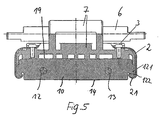
- the hook-shaped projections 121 ends at a distance s in front of the lower edge 14 of the armature, so that enough space remains to the bracket 2 to the hook-shaped projection 121 to hang in the Einitatinut 122 with the Ein cognitiveende 21.
- Bracket 2 in the hooked on the hook-shaped projections 121 state does not protrude beyond the lower edge 14 of the armature, which is the magnetic core enclosing bobbins not damaged or destroyed.
- the bracket 2 are, as shown in FIG. 3, approximately C-shaped in Cross-section formed, for example, spring steel and have a tight bent Einitatiende 21 on and a rounded bent approximately at right angles longer end 22 with Medicarekantetem end 23 for attachment on the receiving part.
- This attachment end 22 of the bracket 2 is Also provided through hole 20 for receiving a screw 3.
- the receiving part 5 is on top 19 of the armature 1 shown in FIG. 2 placed.
- the brackets 2 are assigned each attachment regions 52, 53 provided on the receiving part, Fig. 4, here additional insertion slots 51, 50 in order to appropriate pockets the receiving part 5, the strap ends 22 introduce.
- the screws 3 can then from the top into corresponding screw holes in the receiving part. 5 be screwed. This is a rigid connection of the armature 1 to the Receiving part 5 by means of two bracket 2 takes place.
- Brackets are attached to a receiving part, with each side of the Ankers two brackets 2 are provided, as shown for example in FIG. 7.
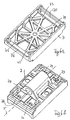
- a receptacle for an anchor that is attached with four straps is to see for example in Figs. 6a and 6b, the receiving part 7 has this corresponding to four receiving areas on its top four screw holes 71, 72, 73, 74 for fixing the brackets by means of screws.
- the Receiving part 7 further has on its upper side a bearing bore 70th for a bolt 6, see Fig. 7, on for the attachment of the receiving part with Anchor.
- bearing surfaces 75, 76 are provided for the proper installation of the armature 1.
- FIG. 5 shows the longitudinal section through the anchor fastening according to FIG. 7 shown.
- FIGs. 8a and 8b is another possibility of the embodiment of a Receiving parts 7 shown for attachment of the anchor by means of four brackets 2, wherein this receiving part of the receiving part 7 according to 6a, 6b characterized by a simpler surface design.
- this receiving part of the receiving part 7 according to 6a, 6b characterized by a simpler surface design.
- top damping components 8 applied become.
- the invention enables a simple anchor attachment, the versatile applicable is, whereby an economical production is given and in the a maximum utilization of the anchor volume with respect to the driving force is reached.
Landscapes
- Physics & Mathematics (AREA)
- Electromagnetism (AREA)
- Electromagnets (AREA)
Claims (7)
- Commutateur électromagnétique comprenant un noyau magnétique muni d'un induit (1) relié à une pièce d'accueil (5 ; 7), caractérisé en ce que l'induit (1) présente sur deux côtés opposés l'un à l'autre des parties en saillie (121) latérales en forme de crochets en formant une rainure d'accrochage (122) qui fait face au noyau magnétique et au moins un étrier (2) est accroché à chacun des deux côtés opposés l'un à l'autre de la partie en saillie (121) en forme de crochet de manière à l'entourer avec une extrémité d'accrochage (21) courbée dans la rainure d'accrochage (122) de manière à ce que l'induit (1) puisse être accroché à au moins deux étriers (2) disposés en opposition l'un à l'autre et la pièce d'accueil (5) ou (7) soit disposée sur le dessus (19) de l'induit (1) à l'opposé du noyau magnétique et les étriers (2) recouvrent la pièce d'accueil (5 ; 7) avec leur autre extrémité de fixation (22) coudée et l'étrier (2) peut être fixé à la pièce d'accueil (5 ; 7) au moyen d'une vis (3).
- Commutateur selon la revendication 1, caractérisé en ce que l'étrier (2) est réalisé en forme de C avec une extrémité d'accrochage (21) coudée courte et une extrémité d'accrochage (22) coudée longue arrondie approximativement en angle droit.
- Commutateur selon la revendication 1 ou 2, caractérisé en ce que l'extrémité de fixation (22) présente un trou ou un trou de vis (20) pour accueillir une vis (3).
- Commutateur selon l'une des revendications 1 à 3, caractérisé en ce que les parties en saillie (121) latérales en forme de crochet de l'induit (1) s'étendent au maximum jusqu'au dessous (14) de l'induit qui fait face au noyau magnétique et l'espace (S) restant est suffisant pour accueillir l'extrémité d'accrochage (21) de l'étrier (2).
- Commutateur selon l'une des revendications 1 à 4, caractérisé en ce que la liaison entre l'induit et la pièce d'accueil au moyen des étriers correspond à une liaison rigide.
- Commutateur selon l'une des revendications 1 à 5, caractérisé en ce que pour les commutateurs de très grande puissance tels que les commutateurs sous vide, quatre étriers (2) sont prévus pour relier l'induit (1) avec la pièce d'accueil (7).
- Commutateur selon l'une des revendications 1 à 6, caractérisé en ce que pour fixer les étriers (2), la pièce d'accueil (5 ou 7) est équipée sur son dessus de zones de fixation correspondantes comprenant un trou de vis.
Applications Claiming Priority (2)
| Application Number | Priority Date | Filing Date | Title |
|---|---|---|---|
| DE1998114399 DE19814399C1 (de) | 1998-03-31 | 1998-03-31 | Elektromagnetisches Schaltgerät |
| DE19814399 | 1998-03-31 |
Publications (3)
| Publication Number | Publication Date |
|---|---|
| EP0948017A2 EP0948017A2 (fr) | 1999-10-06 |
| EP0948017A3 EP0948017A3 (fr) | 2000-10-11 |
| EP0948017B1 true EP0948017B1 (fr) | 2005-08-24 |
Family
ID=7863110
Family Applications (1)
| Application Number | Title | Priority Date | Filing Date |
|---|---|---|---|
| EP19990104165 Expired - Lifetime EP0948017B1 (fr) | 1998-03-31 | 1999-03-02 | Appareil interrupteur électromagnétique |
Country Status (3)
| Country | Link |
|---|---|
| EP (1) | EP0948017B1 (fr) |
| CN (1) | CN1136597C (fr) |
| DE (1) | DE19814399C1 (fr) |
Families Citing this family (2)
| Publication number | Priority date | Publication date | Assignee | Title |
|---|---|---|---|---|
| DE19732324A1 (de) | 1997-07-28 | 1999-02-04 | Kloeckner Moeller Gmbh | Schaltungsanordnung und Verfahren zur Speicherplatzverwaltung und zur Abarbeitung von Anwenderprogrammen in Kleinsteuerungen |
| DE102004053791A1 (de) * | 2004-11-08 | 2006-05-24 | Siemens Ag | Elektromagnetisches Schaltgerät |
Family Cites Families (5)
| Publication number | Priority date | Publication date | Assignee | Title |
|---|---|---|---|---|
| DE1615938B1 (de) * | 1968-01-02 | 1971-12-09 | Calor Emag Elek Zitaets Ag | Elektromagnetisches Schaltgeraet,insbesondere Schuetz mit E-Anker |
| DE2514904C3 (de) * | 1975-04-05 | 1979-12-06 | Brown, Boveri & Cie Ag, 6800 Mannheim | Elektromagnetisches Schaltgerät |
| DE2943440C2 (de) * | 1979-10-26 | 1984-09-06 | Nixdorf Computer Ag, 4790 Paderborn | Klappankermagnet |
| KR840003135A (ko) * | 1982-02-03 | 1984-08-13 | 카다야마 히도 하지로 | 전력 개폐장치 |
| DE29622093U1 (de) * | 1996-12-19 | 1997-02-27 | Siemens AG, 80333 München | Elektromagnetisches Relais |
-
1998
- 1998-03-31 DE DE1998114399 patent/DE19814399C1/de not_active Expired - Lifetime
-
1999
- 1999-03-02 EP EP19990104165 patent/EP0948017B1/fr not_active Expired - Lifetime
- 1999-03-30 CN CNB99103466XA patent/CN1136597C/zh not_active Expired - Lifetime
Also Published As
| Publication number | Publication date |
|---|---|
| DE19814399C1 (de) | 1999-10-21 |
| EP0948017A3 (fr) | 2000-10-11 |
| HK1021773A1 (en) | 2000-06-30 |
| EP0948017A2 (fr) | 1999-10-06 |
| CN1233845A (zh) | 1999-11-03 |
| CN1136597C (zh) | 2004-01-28 |
Similar Documents
| Publication | Publication Date | Title |
|---|---|---|
| EP3254340B1 (fr) | Châssis de support pour connector électrique modulaire | |
| EP1133038B1 (fr) | Porte-câbles pour fixer des câbles dans une structure de véhicule | |
| DE10008820A1 (de) | Anschlußverbindungsvorrichtung mit einem Rückhalteaufbau und dem dazugehörigen Verfahren | |
| DE2835316C2 (fr) | ||
| DE19814399C1 (de) | Elektromagnetisches Schaltgerät | |
| DE102015205322B4 (de) | Einheit aus Anschlussvorrichtung und spiral- oder schraubenförmig ausgebildeter Zugfeder | |
| EP0284740B1 (fr) | Dispositif de suspension pour lampes | |
| EP0263390A2 (fr) | Borne à vis | |
| DE10261473B4 (de) | Elektromagnetisches Relais | |
| DE3539392C2 (fr) | ||
| DE69114752T2 (de) | Klemme zur Befestigung von Klammern an Anschlusselementen. | |
| DE102006041803B4 (de) | Vorrichtung zur Befestigung eines Gerätes an einer Tragschiene | |
| DE3802393C2 (fr) | ||
| DE29515362U1 (de) | Isolator | |
| DE20320156U1 (de) | Stapelbarer Lautsprecheraufbau | |
| DE2007397C3 (de) | Elektrisches Meßwerk | |
| DE1589508C (de) | Kurzschlußnnganordnung fur U oder E förmige lamellierte Magnetkerne | |
| EP4215250A1 (fr) | Crochet pour anneaux de corde sur un trampolin | |
| DE3333460A1 (de) | Magnetkern | |
| DE2701846C2 (de) | Anordnung zur Halterung von Kontaktleisten in zweigeteilten Gehäusen | |
| AT391381B (de) | Klemmvorrichtung fuer den anschluss von elektrischen leiterenden | |
| DE2036482C3 (de) | Elektromagnetisches Schütz | |
| DE202023100355U1 (de) | Anschlagmodul | |
| AT333881B (de) | Verankerungsvorrichtung zum losbaren befestigen von gegenstanden an einer unterlage | |
| DE2514904A1 (de) | Elektromagnetisches schaltgeraet |
Legal Events
| Date | Code | Title | Description |
|---|---|---|---|
| PUAI | Public reference made under article 153(3) epc to a published international application that has entered the european phase |
Free format text: ORIGINAL CODE: 0009012 |
|
| AK | Designated contracting states |
Kind code of ref document: A2 Designated state(s): CH FR IT LI SE |
|
| AX | Request for extension of the european patent |
Free format text: AL;LT;LV;MK;RO;SI |
|
| PUAL | Search report despatched |
Free format text: ORIGINAL CODE: 0009013 |
|
| AK | Designated contracting states |
Kind code of ref document: A3 Designated state(s): AT BE CH CY DE DK ES FI FR GB GR IE IT LI LU MC NL PT SE |
|
| AX | Request for extension of the european patent |
Free format text: AL;LT;LV;MK;RO;SI |
|
| 17P | Request for examination filed |
Effective date: 20010321 |
|
| AKX | Designation fees paid |
Free format text: CH FR IT LI SE |
|
| REG | Reference to a national code |
Ref country code: DE Ref legal event code: 8566 |
|
| GRAP | Despatch of communication of intention to grant a patent |
Free format text: ORIGINAL CODE: EPIDOSNIGR1 |
|
| GRAS | Grant fee paid |
Free format text: ORIGINAL CODE: EPIDOSNIGR3 |
|
| GRAA | (expected) grant |
Free format text: ORIGINAL CODE: 0009210 |
|
| AK | Designated contracting states |
Kind code of ref document: B1 Designated state(s): CH FR IT LI SE |
|
| PG25 | Lapsed in a contracting state [announced via postgrant information from national office to epo] |
Ref country code: IT Free format text: LAPSE BECAUSE OF FAILURE TO SUBMIT A TRANSLATION OF THE DESCRIPTION OR TO PAY THE FEE WITHIN THE PRE;WARNING: LAPSES OF ITALIAN PATENTS WITH EFFECTIVE DATE BEFORE 2007 MAY HAVE OCCURRED AT ANY TIME BEFORE 2007. THE CORRECT EFFECTIVE DATE MAY BE DIFFERENT FROM THE ONE RECORDED.SCRIBED TIME-LIMIT Effective date: 20050824 |
|
| RTI1 | Title (correction) |
Free format text: ELECTROMAGNETIC SWITCHING DEVICE |
|
| REG | Reference to a national code |
Ref country code: CH Ref legal event code: EP |
|
| REG | Reference to a national code |
Ref country code: CH Ref legal event code: NV Representative=s name: DTS ZUERICH SCHWEIZER- UND EUROPAEISCHE PATENTANWA |
|
| REG | Reference to a national code |
Ref country code: SE Ref legal event code: TRGR |
|
| ET | Fr: translation filed | ||
| PLBE | No opposition filed within time limit |
Free format text: ORIGINAL CODE: 0009261 |
|
| STAA | Information on the status of an ep patent application or granted ep patent |
Free format text: STATUS: NO OPPOSITION FILED WITHIN TIME LIMIT |
|
| 26N | No opposition filed |
Effective date: 20060526 |
|
| REG | Reference to a national code |
Ref country code: CH Ref legal event code: PCAR Representative=s name: DTS ZUERICH; CH |
|
| REG | Reference to a national code |
Ref country code: CH Ref legal event code: PCAR Free format text: DTS ZUERICH;RESIRAIN 1;8125 ZOLLIKERBERG (CH) |
|
| REG | Reference to a national code |
Ref country code: FR Ref legal event code: PLFP Year of fee payment: 18 |
|
| REG | Reference to a national code |
Ref country code: FR Ref legal event code: PLFP Year of fee payment: 19 |
|
| REG | Reference to a national code |
Ref country code: FR Ref legal event code: PLFP Year of fee payment: 20 |
|
| PGFP | Annual fee paid to national office [announced via postgrant information from national office to epo] |
Ref country code: CH Payment date: 20180226 Year of fee payment: 20 |
|
| PGFP | Annual fee paid to national office [announced via postgrant information from national office to epo] |
Ref country code: FR Payment date: 20180220 Year of fee payment: 20 Ref country code: SE Payment date: 20180226 Year of fee payment: 20 |
|
| REG | Reference to a national code |
Ref country code: CH Ref legal event code: PL |