EP0948083A2 - Schleifenantennenanordnung und ihre Verwendung in einem Datenverarbeitungsgerät mit Wechselspeichermedium - Google Patents
Schleifenantennenanordnung und ihre Verwendung in einem Datenverarbeitungsgerät mit Wechselspeichermedium Download PDFInfo
- Publication number
- EP0948083A2 EP0948083A2 EP99104083A EP99104083A EP0948083A2 EP 0948083 A2 EP0948083 A2 EP 0948083A2 EP 99104083 A EP99104083 A EP 99104083A EP 99104083 A EP99104083 A EP 99104083A EP 0948083 A2 EP0948083 A2 EP 0948083A2
- Authority
- EP
- European Patent Office
- Prior art keywords
- loop antenna
- main body
- data processing
- processing apparatus
- antenna main
- Prior art date
- Legal status (The legal status is an assumption and is not a legal conclusion. Google has not performed a legal analysis and makes no representation as to the accuracy of the status listed.)
- Withdrawn
Links
Images



Classifications
-
- G—PHYSICS
- G06—COMPUTING OR CALCULATING; COUNTING
- G06K—GRAPHICAL DATA READING; PRESENTATION OF DATA; RECORD CARRIERS; HANDLING RECORD CARRIERS
- G06K17/00—Methods or arrangements for effecting co-operative working between equipments covered by two or more of main groups G06K1/00 - G06K15/00, e.g. automatic card files incorporating conveying and reading operations
-
- H—ELECTRICITY
- H01—ELECTRIC ELEMENTS
- H01Q—ANTENNAS, i.e. RADIO AERIALS
- H01Q1/00—Details of, or arrangements associated with, antennas
- H01Q1/12—Supports; Mounting means
- H01Q1/22—Supports; Mounting means by structural association with other equipment or articles
- H01Q1/2208—Supports; Mounting means by structural association with other equipment or articles associated with components used in interrogation type services, i.e. in systems for information exchange between an interrogator/reader and a tag/transponder, e.g. in Radio Frequency Identification [RFID] systems
- H01Q1/2225—Supports; Mounting means by structural association with other equipment or articles associated with components used in interrogation type services, i.e. in systems for information exchange between an interrogator/reader and a tag/transponder, e.g. in Radio Frequency Identification [RFID] systems used in active tags, i.e. provided with its own power source or in passive tags, i.e. deriving power from RF signal
-
- G—PHYSICS
- G06—COMPUTING OR CALCULATING; COUNTING
- G06F—ELECTRIC DIGITAL DATA PROCESSING
- G06F13/00—Interconnection of, or transfer of information or other signals between, memories, input/output devices or central processing units
-
- H—ELECTRICITY
- H01—ELECTRIC ELEMENTS
- H01Q—ANTENNAS, i.e. RADIO AERIALS
- H01Q1/00—Details of, or arrangements associated with, antennas
- H01Q1/12—Supports; Mounting means
- H01Q1/22—Supports; Mounting means by structural association with other equipment or articles
-
- H—ELECTRICITY
- H01—ELECTRIC ELEMENTS
- H01Q—ANTENNAS, i.e. RADIO AERIALS
- H01Q1/00—Details of, or arrangements associated with, antennas
- H01Q1/48—Earthing means; Earth screens; Counterpoises
-
- H—ELECTRICITY
- H01—ELECTRIC ELEMENTS
- H01Q—ANTENNAS, i.e. RADIO AERIALS
- H01Q3/00—Arrangements for changing or varying the orientation or the shape of the directional pattern of the waves radiated from an antenna or antenna system
- H01Q3/44—Arrangements for changing or varying the orientation or the shape of the directional pattern of the waves radiated from an antenna or antenna system varying the electric or magnetic characteristics of reflecting, refracting, or diffracting devices associated with the radiating element
-
- H—ELECTRICITY
- H01—ELECTRIC ELEMENTS
- H01Q—ANTENNAS, i.e. RADIO AERIALS
- H01Q7/00—Loop antennas with a substantially uniform current distribution around the loop and having a directional radiation pattern in a plane perpendicular to the plane of the loop
- H01Q7/005—Loop antennas with a substantially uniform current distribution around the loop and having a directional radiation pattern in a plane perpendicular to the plane of the loop with variable reactance for tuning the antenna
Definitions
- the present invention relates to a loop antenna used for a data processing apparatus having a radio communication function for conducting radio transmission and reception between the data processing apparatus and a removable data storing medium having a radio communication function, and thereby conducting predetermined data processing such as data transmission and reception with the removable data storing medium.
- the present invention further relates to the removable data storing medium including this loop antenna.
- radio waves each having a strong electric field strength in order to conduct communication stably without being affected by its environment such as noise. Because of the stipulation of the radio law, however, it is impossible to radiate a radio wave having an unlimited strong electric field strength from a data processing apparatus. In the radio law, therefore, it is permitted to radiate a certain fixed strong radio wave for a specific frequency. However, the present frequency is strictly stipulated, and sufficient care is necessary for its use.
- ⁇ /2 ⁇ is located near a measurement distance of 3 m stipulated by the radio law.
- the radio law When calculating the strength of a radiant electric field, it is typically difficult to make the theoretical calculation coincide with actually measured values when the distance is in the vicinity of ⁇ /2 ⁇ .
- the environment of measurement also exerts a great influence. In other words, if an antenna is designed on a desk on the basis of various conditions and a measurement is actually conducted in the vicinity of 3 m, then a value largely different from the design value is obtained, and the radio law cannot be satisfied in many cases.
- a removable data storing medium having a loop antenna it is desirable to send a signal with an electric strength as strong as possible.
- the electric strength is regulated by the radio law. Therefore, it is desirable to make an adjustment and ship the medium as a storing medium having the very highest electric field strength the regulation range will permit. If the electric field strength is calculated in a design stage and actual measured data is derived, then a portion other than the antenna portion functions as an antenna, and a very large difference occurs between the theoretical value and the actual value. In such a state that the electric field strength cannot be controlled accurately, therefore, there is a problem that it is impossible to design and ship the medium as a storing medium having the very highest electric field strength the radio law will permit.
- An object of the present invention is to provide a loop antenna for accurately implementing the electric field strength requested by the radio law by providing ground in parallel to the main body of the antenna to stabilize the electric field characteristic and making the design value of the antenna coincide with the actual measured value, and a removable data storing medium using this loop antenna.
- an antenna device includes a loop antenna main body having a predetermined aperture area, and a conductor element insulated from the loop antenna main body, connected to a ground potential, and formed in parallel with the loop antenna main body.
- the conductor element insulated from the loop main body is disposed in parallel with the loop main body which tends to become unstable in the electric field characteristic.
- the conductor element functions as the ground for the antenna main body. Since the electric field characteristic of the antenna main body can thus be stabilized, it becomes possible to bring the electric field strength in the design stage close to that in the actual measurement stage as compared with the conventional technique. In the design stage, therefore, it becomes possible to calculate the accurate electric field strength. It thus becomes possible to implement a loop antenna having a characteristic of a value which is infinitely close to the electric field strength requested by the radio law. As a result, the output of, for example, the removable data storing medium using this loop antenna has an electric field strength which is infinitely close to the electric field strength permitted by the radio law. As compared with the conventional technique, therefore, a higher value can be obtained.
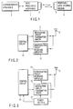
- FIG. 1 schematically shows the configuration of a radio communication system according to the present embodiment.
- this radio communication system includes a data processing apparatus 1 having a radio communication function, a loop antenna 2 of the data processing apparatus 1, a superordinate apparatus 3 for the data processing apparatus 1, a removable data storing medium 4 having a radio communication function, and a loop antenna 5 of the removable data storing medium 4.
- the data processing apparatus 1 conducts radio transmission and reception with the removable data storing medium. Thereby the data processing apparatus 1 transmits data to the removable data storing medium 4 and receives data therefrom. As a result, predetermined data processing is conducted.
- FIG. 2 schematically shows an example of a basic configuration of the data processing apparatus 1.
- the data processing apparatus 1 includes a modulating circuit transmitter driver 11 and a demodulating circuit receiving amplifier 12.
- the loop antenna 2 is connected to the modulating circuit transmitter driver 11 and the demodulating circuit receiving amplifier 12.
- the data processing apparatus 1 further includes a control circuit 13 for executing various kinds of processing. To the control circuit 13, the modulating circuit transmitter driver 11 and the demodulating circuit receiving amplifier 12 are connected.
- Data generated by the superordinate apparatus 3 are sent to the control circuit 13.
- a signal provided with the data in the control circuit 13 is modulated and amplified in the modulating circuit transmitter driver 11 and supplied to the loop antenna 2.
- the loop antenna 2 radiates the signal supplied from the modulating circuit transmitter driver 11 into space as a radio wave.
- a radio wave transmitted from the removable data storing medium 4 is received by the loop antenna 2 of the data processing apparatus 1, and sent to the demodulating circuit receiving amplifier 12.
- the demodulating circuit receiving amplifier 12 processing such as amplification and demodulation is conducted on the received signal, and received data is obtained.
- the received data thus obtained is sent to the control circuit 13.
- predetermined processing based upon the received data is conducted.
- FIG. 16A is an exterior view of the removable data storing medium having the loop antenna of the present invention.
- FIG. 16B is a side view of the removable data storing medium having the loop antenna of the present invention.
- FIGS. 16A and 16B an example of the removable data storing medium having the loop antenna of the present invention is shown.
- the loop antenna which is a feature of the present invention will hereafter be described in detail.
- FIG. 3 schematically shows an example of a basic configuration of the removable data storing medium 4.
- the removable data storing medium 4 includes a demodulating circuit receiving amplifier 21 and a modulating circuit transmitter driver 22.
- the loop antenna 5 is connected to the demodulating circuit receiving amplifier 21 and the modulating circuit transmitter driver 22, the loop antenna 5 is connected.
- the removable data storing medium 4 further includes a control circuit 23 for executing various kinds of processing.
- the demodulating circuit receiving amplifier 21 and the modulating circuit transmitter driver 22 are connected.
- a power section 23 such as a battery is provided to supply operation power to the respective circuits.
- the radio wave radiated into space by the data processing apparatus 1 is received by the loop antenna 5.
- the received signal is sent to the demodulating circuit receiving amplifier 21.
- processing such as amplification and demodulation is conducted on the received signal to obtain received data.
- the received data thus obtained is sent to the control circuit 23.
- predetermined processing based upon the received data is conducted.
- the modulating circuit transmitter driver 22 modulates and amplifies the transmission data, and supplies it to the loop antenna 5.
- the loop antenna 5 radiates a signal supplied from the modulating circuit transmitter driver 22 into space as a radio wave.
- the data processing apparatus 1 application to, for example, a radio card reader/writer is conceivable.
- the removable data Storing medium 4 application to, for example, a radio card used as a commutation ticket or the like is conceivable.
- application to, for example, an automatic ticket barrier apparatus is conceivable as the superordinate apparatus 3.
- a battery is used as the power section 24 .
- a power wave may be transmitted from the data processing apparatus 1.
- power used within the removable data storing medium 4 may be generated from the power wave.
- loop antenna 2 used in the data processing apparatus 1 will be described in detail.
- FIG. 4 shows a typical example of a loop antenna. If a loop antenna 31 shown in FIG. 4 is replaced by a circuit element, it becomes an inductor.
- the loop antenna is a rectangular loop coil having two turns, and a matching circuit 32 is connected thereto.
- the matching circuit 32 is a resonance circuit and an impedance conversion circuit. Typically, in the field of radio communication devices, impedance conversion to 50 ⁇ is conducted. Furthermore, a signal source 33 is provided.
- FIG. 5 a radiation system and a measurement system of the loop antenna are shown.
- the loop antenna is considered as that having one turn for brevity.
- a loop antenna 41 having one turn, a matching circuit 42, a signal generator 43, an antenna 44 for measurement, and a spectrum analyzer 45 are provided.
- ⁇ /2 ⁇ is approximately 3 m. In other words, the frequency is approximately ten and several MHz.
- a loop antenna is often used as the antenna 44. A signal transmitted from the signal generator 43 is passed through the impedance conversion circuit and the resonance circuit in the matching circuit 42, and radiated from the loop antenna 42.
- a radio wave radiated from the loop antenna 41 is received by the antenna 44.
- a level of a received signal is confirmed in the spectrum analyzer 45.
- the radiant electric field strength of the loop antenna 41 can be calculated.
- FIG. 6 shows a radiant electric field strength model from a minute loop coil.
- a minute loop coil 51 considered as a design value, and polar coordinate representation 52 used in the electromagnetics or the like are shown.
- formulas concerning the electric field strength and the magnetic field strength at a point P are already known through literature, and they are omitted here.
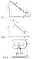
- FIG. 7 shows a solution of radiation from a minute loop antenna. Letting the distance between the antennas be r, a characteristic curve 61 represents a magnetic field Hr component, and a characteristic curve 62 represents a magnetic field H ⁇ component. A characteristic curve 63 represents a line of 1/r3. Paying attention to the vicinity of 3 m, it is an area where a 1/r term, a 1/r2 term, and a 1/r3 term in the Hr component and the H ⁇ component are equal, and the calculated value does not readily coincide with the actually measured value. If a transmission antenna of bad performance is used and an electric field strength at this point is measured, an electric field strength largely different from its design value is measured.
- FIG. 8 shows an example of distance versus radiant electric field (magnetic field) strength in the case where an antenna of bad performance is used.
- the Hr component is important in antennas. Therefore, only the Hr component is shown in the graph of FIG. 8.
- a characteristic curve 71 shows measured values, and a characteristic curve 72 shows a line of 1/r3.
- the characteristic curve 71 largely differs from the design value, and dips in the vicinity of 3 m. Therefore, the component is largely disturbed thereafter.
- FIG. 9 shows a loop antenna according to a first embodiment.
- a ground pattern serving as a platelike conductor is disposed along a loop antenna main body. In this example, it is implemented by using a printed wiring board. Alternatively, an ordinary wiring material may be used, and there is no difference in characteristic. In the embodiment hereafter described, the ground pattern is implemented by a printed wiring board.
- a loop antenna main body 81 having a predetermined aperture area is shown.
- a rectangular loop coil having one turn is used.
- a printed wiring board 83 is interposed between a ground pattern 82 serving as a platelike conductor and a loop antenna main body 81.
- the ground pattern 82 is formed across from the loop antenna main body 81 and along the loop antenna main body 81.
- the ground pattern 82 is connected to a ground terminal (grounding point) of the loop antenna main body 81.
- FIG. 10 shows a loop antenna according to a second embodiment.
- a ferrite plate serving as a platelike magnetic substance is disposed on the back side of the antenna main body shown in FIG. 9.
- a ferrite plate 85 serving as a platelike magnetic substance is disposed via a spacer 84.
- the spacer 84 is an insulative spacer for adjusting the gap between the ferrite plate 85 and the printed wiring board 83.
- the ferrite plate 85 has a high permittivity.
- the magnetic field strength in the vicinity of the loop antenna main body 81 tends to become large. Therefore, the electric field strength at a distance of 3 m is relatively attenuated together with the electric field strength in the vicinity of the antenna. Furthermore, by disposing the ground pattern 82, the disturbance of the radiant electric field strength at a distance of 3 m can be suppressed.
- FIG. 11 shows a loop antenna according to a third embodiment.
- a copper plate serving as a platelike conductor is stuck to the back side of the ferrite plate.
- a copper plate 86 serving as a platelike conductor is stuck to the back side of a ferrite plate 85 in such a state that electric connection with the ferrite plate 85 is maintained.
- the copper plate 86 is electrically connected to ground of the loop antenna main body 81. Furthermore, the copper plate 86 is electrically connected to the ferrite plate 85.
- FIGS. 12A and 12B show a loop antenna according to a fourth embodiment, and relate to disposition of a feeding point of the rectangular loop antenna main body and the ground pattern.
- the loop antenna main body 81 takes the shape of a rectangle having short sides "a" and long sides "b," i.e., b/a > 1, then it is necessary to dispose the feeding point near the center of the long side "b" without fail.
- the feeding point is disposed on the short side "a" or at an end of the long side "b,” the radiant electric field strength pattern at a distance of 3 m is disturbed.
- the transmission antenna is rotated at a distance of 3 m, then the ideal radiant pattern is not observed, and the pattern takes a distorted shape.
- a part of a ground pattern 82 is extended from an opposite side toward the feeding point on the long side "b" of the loop antenna main body 81.
- An extension 82a is connected to ground of the loop antenna main body 81 via a through hole 87 near the feeding point.
- the through hole 87 is formed in a printed wiring board 83 to connect the extension 82a of the ground pattern 82 to the ground of the loop antenna main body 81.
- FIG. 13 shows an example of the matching circuit.
- the matching circuit includes a loop antenna main body 81, a ground pattern 82, a resonance capacitor 91, a Q adjusting resistor 92, an impedance adjusting capacitor 93, and a connector 94. According to how these components are arranged, the electric field strength characteristic at a distance of 3 m is changed.
- FIG. 14 is a diagram concerning the layout of the matching circuit shown in FIG. 13.
- the loop antenna the loop antenna main body 81, the ground pattern 82, the resonance capacitor 91, the Q adjusting resistor 92, the impedance adjusting capacitor 93, and the connector 94. It is necessary to dispose the resonance capacitor 91 and the Q adjusting resistor 92 on the line of the loop antenna main body 81 so as to be located on a straight line.
- the resonance capacitor 91 and the Q adjusting resistor 92 forms a part of a resonance circuit, and a large current flows through them. Therefore, radiation from these components poses a problem.
- radiation from the resistor 92 and the capacitor 91 can be considered as a part of radiation from the loop antenna main body 81.
- FIG. 15 shows an example of actually measured values in the antenna configuration shown in FIG. 14. In trial manufacture conducted lately, the actually measured value could be let in an error of approximately 1 dB from the design value.
- a characteristic curve 73 represents a line of 1/r3 and a characteristic curve 74 represents actually measured values.
- the present invention is capable of making the actually measured value of an antenna coincide with the design value by providing the ground in parallel with the antenna main body and thus stabilizing the electric field characteristic, and providing a loop antenna implementing accurately the electric field strength requested by the radio law, and a removable data storing medium using this loop antenna.
Landscapes
- Engineering & Computer Science (AREA)
- Theoretical Computer Science (AREA)
- Physics & Mathematics (AREA)
- General Physics & Mathematics (AREA)
- General Engineering & Computer Science (AREA)
- Details Of Aerials (AREA)
- Near-Field Transmission Systems (AREA)
- Support Of Aerials (AREA)
- Aerials With Secondary Devices (AREA)
Applications Claiming Priority (2)
| Application Number | Priority Date | Filing Date | Title |
|---|---|---|---|
| JP8687098 | 1998-03-31 | ||
| JP08687098A JP4260917B2 (ja) | 1998-03-31 | 1998-03-31 | ループアンテナ |
Publications (2)
| Publication Number | Publication Date |
|---|---|
| EP0948083A2 true EP0948083A2 (de) | 1999-10-06 |
| EP0948083A3 EP0948083A3 (de) | 2000-09-13 |
Family
ID=13898867
Family Applications (1)
| Application Number | Title | Priority Date | Filing Date |
|---|---|---|---|
| EP99104083A Withdrawn EP0948083A3 (de) | 1998-03-31 | 1999-03-18 | Schleifenantennenanordnung und ihre Verwendung in einem Datenverarbeitungsgerät mit Wechselspeichermedium |
Country Status (4)
| Country | Link |
|---|---|
| US (1) | US6243045B1 (de) |
| EP (1) | EP0948083A3 (de) |
| JP (1) | JP4260917B2 (de) |
| KR (1) | KR100323343B1 (de) |
Cited By (60)
| Publication number | Priority date | Publication date | Assignee | Title |
|---|---|---|---|---|
| EP1229482A3 (de) * | 2001-02-03 | 2003-04-02 | SAMSUNG ELECTRONICS Co. Ltd. | Antenne für Kartenleser |
| US8228765B2 (en) | 2006-06-30 | 2012-07-24 | Murata Manufacturing Co., Ltd. | Optical disc |
| US8299929B2 (en) | 2006-09-26 | 2012-10-30 | Murata Manufacturing Co., Ltd. | Inductively coupled module and item with inductively coupled module |
| US8336786B2 (en) | 2010-03-12 | 2012-12-25 | Murata Manufacturing Co., Ltd. | Wireless communication device and metal article |
| US8381997B2 (en) | 2009-06-03 | 2013-02-26 | Murata Manufacturing Co., Ltd. | Radio frequency IC device and method of manufacturing the same |
| US8400365B2 (en) | 2009-11-20 | 2013-03-19 | Murata Manufacturing Co., Ltd. | Antenna device and mobile communication terminal |
| US8413907B2 (en) | 2007-07-17 | 2013-04-09 | Murata Manufacturing Co., Ltd. | Wireless IC device and electronic apparatus |
| US8424769B2 (en) | 2010-07-08 | 2013-04-23 | Murata Manufacturing Co., Ltd. | Antenna and RFID device |
| US8424762B2 (en) | 2007-04-14 | 2013-04-23 | Murata Manufacturing Co., Ltd. | Wireless IC device and component for wireless IC device |
| US8531346B2 (en) | 2007-04-26 | 2013-09-10 | Murata Manufacturing Co., Ltd. | Wireless IC device |
| US8544759B2 (en) | 2009-01-09 | 2013-10-01 | Murata Manufacturing., Ltd. | Wireless IC device, wireless IC module and method of manufacturing wireless IC module |
| US8552870B2 (en) | 2007-07-09 | 2013-10-08 | Murata Manufacturing Co., Ltd. | Wireless IC device |
| US8590797B2 (en) | 2008-05-21 | 2013-11-26 | Murata Manufacturing Co., Ltd. | Wireless IC device |
| US8602310B2 (en) | 2010-03-03 | 2013-12-10 | Murata Manufacturing Co., Ltd. | Radio communication device and radio communication terminal |
| US8613395B2 (en) | 2011-02-28 | 2013-12-24 | Murata Manufacturing Co., Ltd. | Wireless communication device |
| US8676117B2 (en) | 2006-01-19 | 2014-03-18 | Murata Manufacturing Co., Ltd. | Wireless IC device and component for wireless IC device |
| US8680971B2 (en) | 2009-09-28 | 2014-03-25 | Murata Manufacturing Co., Ltd. | Wireless IC device and method of detecting environmental state using the device |
| US8690070B2 (en) | 2009-04-14 | 2014-04-08 | Murata Manufacturing Co., Ltd. | Wireless IC device component and wireless IC device |
| US8718727B2 (en) | 2009-12-24 | 2014-05-06 | Murata Manufacturing Co., Ltd. | Antenna having structure for multi-angled reception and mobile terminal including the antenna |
| US8720789B2 (en) | 2012-01-30 | 2014-05-13 | Murata Manufacturing Co., Ltd. | Wireless IC device |
| US8740093B2 (en) | 2011-04-13 | 2014-06-03 | Murata Manufacturing Co., Ltd. | Radio IC device and radio communication terminal |
| US8757500B2 (en) | 2007-05-11 | 2014-06-24 | Murata Manufacturing Co., Ltd. | Wireless IC device |
| US8770489B2 (en) | 2011-07-15 | 2014-07-08 | Murata Manufacturing Co., Ltd. | Radio communication device |
| US8797225B2 (en) | 2011-03-08 | 2014-08-05 | Murata Manufacturing Co., Ltd. | Antenna device and communication terminal apparatus |
| US8797148B2 (en) | 2008-03-03 | 2014-08-05 | Murata Manufacturing Co., Ltd. | Radio frequency IC device and radio communication system |
| US8810456B2 (en) | 2009-06-19 | 2014-08-19 | Murata Manufacturing Co., Ltd. | Wireless IC device and coupling method for power feeding circuit and radiation plate |
| US8814056B2 (en) | 2011-07-19 | 2014-08-26 | Murata Manufacturing Co., Ltd. | Antenna device, RFID tag, and communication terminal apparatus |
| US8847831B2 (en) | 2009-07-03 | 2014-09-30 | Murata Manufacturing Co., Ltd. | Antenna and antenna module |
| US8853549B2 (en) | 2009-09-30 | 2014-10-07 | Murata Manufacturing Co., Ltd. | Circuit substrate and method of manufacturing same |
| US8870077B2 (en) | 2008-08-19 | 2014-10-28 | Murata Manufacturing Co., Ltd. | Wireless IC device and method for manufacturing same |
| US8878739B2 (en) | 2011-07-14 | 2014-11-04 | Murata Manufacturing Co., Ltd. | Wireless communication device |
| US8905296B2 (en) | 2011-12-01 | 2014-12-09 | Murata Manufacturing Co., Ltd. | Wireless integrated circuit device and method of manufacturing the same |
| US8917211B2 (en) | 2008-11-17 | 2014-12-23 | Murata Manufacturing Co., Ltd. | Antenna and wireless IC device |
| US8937576B2 (en) | 2011-04-05 | 2015-01-20 | Murata Manufacturing Co., Ltd. | Wireless communication device |
| US8944335B2 (en) | 2010-09-30 | 2015-02-03 | Murata Manufacturing Co., Ltd. | Wireless IC device |
| US8976075B2 (en) | 2009-04-21 | 2015-03-10 | Murata Manufacturing Co., Ltd. | Antenna device and method of setting resonant frequency of antenna device |
| US8981906B2 (en) | 2010-08-10 | 2015-03-17 | Murata Manufacturing Co., Ltd. | Printed wiring board and wireless communication system |
| US8991713B2 (en) | 2011-01-14 | 2015-03-31 | Murata Manufacturing Co., Ltd. | RFID chip package and RFID tag |
| US9001001B2 (en) | 2010-06-18 | 2015-04-07 | Murata Manufacturing Co., Ltd. | Communication terminal apparatus and antenna device |
| US9024725B2 (en) | 2009-11-04 | 2015-05-05 | Murata Manufacturing Co., Ltd. | Communication terminal and information processing system |
| US9024837B2 (en) | 2010-03-31 | 2015-05-05 | Murata Manufacturing Co., Ltd. | Antenna and wireless communication device |
| US9104950B2 (en) | 2009-01-30 | 2015-08-11 | Murata Manufacturing Co., Ltd. | Antenna and wireless IC device |
| US9117157B2 (en) | 2009-10-02 | 2015-08-25 | Murata Manufacturing Co., Ltd. | Wireless IC device and electromagnetic coupling module |
| US9165239B2 (en) | 2006-04-26 | 2015-10-20 | Murata Manufacturing Co., Ltd. | Electromagnetic-coupling-module-attached article |
| US9166291B2 (en) | 2010-10-12 | 2015-10-20 | Murata Manufacturing Co., Ltd. | Antenna device and communication terminal apparatus |
| US9178279B2 (en) | 2009-11-04 | 2015-11-03 | Murata Manufacturing Co., Ltd. | Wireless IC tag, reader-writer, and information processing system |
| US9236651B2 (en) | 2010-10-21 | 2016-01-12 | Murata Manufacturing Co., Ltd. | Communication terminal device |
| US9281873B2 (en) | 2008-05-26 | 2016-03-08 | Murata Manufacturing Co., Ltd. | Wireless IC device system and method of determining authenticity of wireless IC device |
| US9378452B2 (en) | 2011-05-16 | 2016-06-28 | Murata Manufacturing Co., Ltd. | Radio IC device |
| US9444143B2 (en) | 2009-10-16 | 2016-09-13 | Murata Manufacturing Co., Ltd. | Antenna and wireless IC device |
| US9460376B2 (en) | 2007-07-18 | 2016-10-04 | Murata Manufacturing Co., Ltd. | Radio IC device |
| US9460320B2 (en) | 2009-10-27 | 2016-10-04 | Murata Manufacturing Co., Ltd. | Transceiver and radio frequency identification tag reader |
| US9461363B2 (en) | 2009-11-04 | 2016-10-04 | Murata Manufacturing Co., Ltd. | Communication terminal and information processing system |
| US9543642B2 (en) | 2011-09-09 | 2017-01-10 | Murata Manufacturing Co., Ltd. | Antenna device and wireless device |
| US9558384B2 (en) | 2010-07-28 | 2017-01-31 | Murata Manufacturing Co., Ltd. | Antenna apparatus and communication terminal instrument |
| US9692128B2 (en) | 2012-02-24 | 2017-06-27 | Murata Manufacturing Co., Ltd. | Antenna device and wireless communication device |
| US9727765B2 (en) | 2010-03-24 | 2017-08-08 | Murata Manufacturing Co., Ltd. | RFID system including a reader/writer and RFID tag |
| US9761923B2 (en) | 2011-01-05 | 2017-09-12 | Murata Manufacturing Co., Ltd. | Wireless communication device |
| US10013650B2 (en) | 2010-03-03 | 2018-07-03 | Murata Manufacturing Co., Ltd. | Wireless communication module and wireless communication device |
| US10235544B2 (en) | 2012-04-13 | 2019-03-19 | Murata Manufacturing Co., Ltd. | Inspection method and inspection device for RFID tag |
Families Citing this family (24)
| Publication number | Priority date | Publication date | Assignee | Title |
|---|---|---|---|---|
| JP2001168618A (ja) * | 1999-12-08 | 2001-06-22 | Smart Card Technologies:Kk | 無接触形icカードシステムにおけるリードライタ用のアンテナ装置 |
| DE60126419D1 (de) * | 2000-09-27 | 2007-03-22 | Rangestar Wireless Inc | Rundstrahlende antenne mit mehreren polarisationen |
| US6563468B2 (en) | 2001-04-27 | 2003-05-13 | Tyco Electronics Logistics Ag | Omni directional antenna with multiple polarizations |
| US6693598B1 (en) | 2000-09-27 | 2004-02-17 | Tyco Electronics Logistics Ag | Omni directional antenna with multiple polarizations |
| US6593886B2 (en) * | 2001-01-02 | 2003-07-15 | Time Domain Corporation | Planar loop antenna |
| US6597318B1 (en) * | 2002-06-27 | 2003-07-22 | Harris Corporation | Loop antenna and feed coupler for reduced interaction with tuning adjustments |
| JP4747294B2 (ja) * | 2005-05-26 | 2011-08-17 | 三菱マテリアル株式会社 | Rfidタグ |
| US7830311B2 (en) * | 2007-07-18 | 2010-11-09 | Murata Manufacturing Co., Ltd. | Wireless IC device and electronic device |
| JP5029371B2 (ja) * | 2008-01-08 | 2012-09-19 | パナソニック株式会社 | アンテナ装置およびその調整方法 |
| USD594445S1 (en) * | 2008-08-11 | 2009-06-16 | Murata Manufacturing Co., Ltd. | Antenna for wireless tag |
| USD594446S1 (en) * | 2008-08-11 | 2009-06-16 | Murata Manufacturing Co., Ltd. | Antenna for wireless tag |
| USD594447S1 (en) * | 2008-08-11 | 2009-06-16 | Murata Manufacturing Co., Ltd. | Antenna for wireless tag |
| JP5054638B2 (ja) | 2008-08-27 | 2012-10-24 | 富士通コンポーネント株式会社 | 通信装置及びこれを用いたシステム |
| JP2010081563A (ja) * | 2008-08-27 | 2010-04-08 | Fujitsu Component Ltd | アンテナ装置及びこれを用いた通信システム |
| USD602479S1 (en) * | 2008-11-14 | 2009-10-20 | Murata Manufacturing Co., Ltd. | Antenna for wireless tag |
| USD602480S1 (en) * | 2008-11-14 | 2009-10-20 | Murata Manufacturing Co., Ltd. | Antenna for wireless tag |
| US20130154887A1 (en) * | 2011-12-15 | 2013-06-20 | Paul W. Hein | Antenna testing enclosures and methods for testing antenna systems therewith |
| JP6145388B2 (ja) * | 2013-10-30 | 2017-06-14 | 日本電産サンキョー株式会社 | 非接触式通信モジュールおよびカードリーダ |
| DE102014106815B4 (de) * | 2014-05-14 | 2024-01-18 | Infineon Technologies Ag | Kommunikationsmodul |
| CN105337027B (zh) * | 2014-06-30 | 2017-08-04 | 比亚迪股份有限公司 | 一种天线模组的制备方法 |
| JP6677602B2 (ja) * | 2016-08-04 | 2020-04-08 | トッパン・フォームズ株式会社 | 識別体 |
| US11769949B2 (en) * | 2016-08-29 | 2023-09-26 | Silicon Laboratories Inc. | Apparatus with partitioned radio frequency antenna and matching network and associated methods |
| CN111194506B (zh) | 2017-09-28 | 2022-04-26 | 株式会社村田制作所 | 天线装置以及具备天线装置的多轴天线装置 |
| CN111384991B (zh) * | 2018-12-31 | 2023-06-30 | 硅实验室公司 | 射频装置 |
Family Cites Families (9)
| Publication number | Priority date | Publication date | Assignee | Title |
|---|---|---|---|---|
| JPS572102A (en) * | 1980-06-04 | 1982-01-07 | Hitachi Ltd | Loop antenna for car-to-ground communication |
| US4373163A (en) * | 1980-07-14 | 1983-02-08 | I.D. Engineering, Inc. | Loop antenna for security systems |
| EP0397755A4 (en) * | 1988-02-04 | 1992-11-04 | Uniscan Ltd. | Magnetic field concentrator |
| US5327148A (en) * | 1993-02-17 | 1994-07-05 | Northeastern University | Ferrite microstrip antenna |
| FR2724263B1 (fr) * | 1994-09-05 | 1996-11-08 | Valeo Electronique | Antenne utilisee pour l'emission ou la reception d'un signal radiofrequence, un emetteur et un recepteur de telecommande et un systeme de telecommande pour vehicule l'incorporant |
| JP3431045B2 (ja) * | 1995-01-18 | 2003-07-28 | 久松 中野 | 円偏波ループアンテナ |
| US5646633A (en) * | 1995-04-05 | 1997-07-08 | Mcdonnell Douglas Corporation | Microstrip antenna having a plurality of broken loops |
| IT1289333B1 (it) * | 1996-06-21 | 1998-10-02 | Alfa Accessori | Antenna per la ricezione e la trasmissione in polarizzazione circolare |
| US5982335A (en) * | 1997-09-25 | 1999-11-09 | Motorola, Inc. | Antenna with low reluctance material positioned to influence radiation pattern |
-
1998
- 1998-03-31 JP JP08687098A patent/JP4260917B2/ja not_active Expired - Fee Related
-
1999
- 1999-03-18 EP EP99104083A patent/EP0948083A3/de not_active Withdrawn
- 1999-03-19 US US09/272,261 patent/US6243045B1/en not_active Expired - Fee Related
- 1999-03-29 KR KR1019990010739A patent/KR100323343B1/ko not_active Expired - Fee Related
Cited By (77)
| Publication number | Priority date | Publication date | Assignee | Title |
|---|---|---|---|---|
| EP1229482A3 (de) * | 2001-02-03 | 2003-04-02 | SAMSUNG ELECTRONICS Co. Ltd. | Antenne für Kartenleser |
| US6642896B2 (en) | 2001-02-03 | 2003-11-04 | Samsung Electronics Co., Ltd. | Reader coil antenna, and non-contacting type card identification system using the same |
| US8676117B2 (en) | 2006-01-19 | 2014-03-18 | Murata Manufacturing Co., Ltd. | Wireless IC device and component for wireless IC device |
| US8725071B2 (en) | 2006-01-19 | 2014-05-13 | Murata Manufacturing Co., Ltd. | Wireless IC device and component for wireless IC device |
| US9165239B2 (en) | 2006-04-26 | 2015-10-20 | Murata Manufacturing Co., Ltd. | Electromagnetic-coupling-module-attached article |
| US8228765B2 (en) | 2006-06-30 | 2012-07-24 | Murata Manufacturing Co., Ltd. | Optical disc |
| US8299929B2 (en) | 2006-09-26 | 2012-10-30 | Murata Manufacturing Co., Ltd. | Inductively coupled module and item with inductively coupled module |
| US8424762B2 (en) | 2007-04-14 | 2013-04-23 | Murata Manufacturing Co., Ltd. | Wireless IC device and component for wireless IC device |
| US8531346B2 (en) | 2007-04-26 | 2013-09-10 | Murata Manufacturing Co., Ltd. | Wireless IC device |
| US8757500B2 (en) | 2007-05-11 | 2014-06-24 | Murata Manufacturing Co., Ltd. | Wireless IC device |
| US8662403B2 (en) | 2007-07-04 | 2014-03-04 | Murata Manufacturing Co., Ltd. | Wireless IC device and component for wireless IC device |
| US8552870B2 (en) | 2007-07-09 | 2013-10-08 | Murata Manufacturing Co., Ltd. | Wireless IC device |
| US8413907B2 (en) | 2007-07-17 | 2013-04-09 | Murata Manufacturing Co., Ltd. | Wireless IC device and electronic apparatus |
| US9830552B2 (en) | 2007-07-18 | 2017-11-28 | Murata Manufacturing Co., Ltd. | Radio IC device |
| US9460376B2 (en) | 2007-07-18 | 2016-10-04 | Murata Manufacturing Co., Ltd. | Radio IC device |
| US8797148B2 (en) | 2008-03-03 | 2014-08-05 | Murata Manufacturing Co., Ltd. | Radio frequency IC device and radio communication system |
| US8973841B2 (en) | 2008-05-21 | 2015-03-10 | Murata Manufacturing Co., Ltd. | Wireless IC device |
| US8590797B2 (en) | 2008-05-21 | 2013-11-26 | Murata Manufacturing Co., Ltd. | Wireless IC device |
| US9022295B2 (en) | 2008-05-21 | 2015-05-05 | Murata Manufacturing Co., Ltd. | Wireless IC device |
| US9281873B2 (en) | 2008-05-26 | 2016-03-08 | Murata Manufacturing Co., Ltd. | Wireless IC device system and method of determining authenticity of wireless IC device |
| US8870077B2 (en) | 2008-08-19 | 2014-10-28 | Murata Manufacturing Co., Ltd. | Wireless IC device and method for manufacturing same |
| US8917211B2 (en) | 2008-11-17 | 2014-12-23 | Murata Manufacturing Co., Ltd. | Antenna and wireless IC device |
| US8544759B2 (en) | 2009-01-09 | 2013-10-01 | Murata Manufacturing., Ltd. | Wireless IC device, wireless IC module and method of manufacturing wireless IC module |
| US9104950B2 (en) | 2009-01-30 | 2015-08-11 | Murata Manufacturing Co., Ltd. | Antenna and wireless IC device |
| US8876010B2 (en) | 2009-04-14 | 2014-11-04 | Murata Manufacturing Co., Ltd | Wireless IC device component and wireless IC device |
| US8690070B2 (en) | 2009-04-14 | 2014-04-08 | Murata Manufacturing Co., Ltd. | Wireless IC device component and wireless IC device |
| US8976075B2 (en) | 2009-04-21 | 2015-03-10 | Murata Manufacturing Co., Ltd. | Antenna device and method of setting resonant frequency of antenna device |
| US9203157B2 (en) | 2009-04-21 | 2015-12-01 | Murata Manufacturing Co., Ltd. | Antenna device and method of setting resonant frequency of antenna device |
| US9564678B2 (en) | 2009-04-21 | 2017-02-07 | Murata Manufacturing Co., Ltd. | Antenna device and method of setting resonant frequency of antenna device |
| US8381997B2 (en) | 2009-06-03 | 2013-02-26 | Murata Manufacturing Co., Ltd. | Radio frequency IC device and method of manufacturing the same |
| US8810456B2 (en) | 2009-06-19 | 2014-08-19 | Murata Manufacturing Co., Ltd. | Wireless IC device and coupling method for power feeding circuit and radiation plate |
| US8847831B2 (en) | 2009-07-03 | 2014-09-30 | Murata Manufacturing Co., Ltd. | Antenna and antenna module |
| US8680971B2 (en) | 2009-09-28 | 2014-03-25 | Murata Manufacturing Co., Ltd. | Wireless IC device and method of detecting environmental state using the device |
| US8853549B2 (en) | 2009-09-30 | 2014-10-07 | Murata Manufacturing Co., Ltd. | Circuit substrate and method of manufacturing same |
| US9117157B2 (en) | 2009-10-02 | 2015-08-25 | Murata Manufacturing Co., Ltd. | Wireless IC device and electromagnetic coupling module |
| US9444143B2 (en) | 2009-10-16 | 2016-09-13 | Murata Manufacturing Co., Ltd. | Antenna and wireless IC device |
| US9460320B2 (en) | 2009-10-27 | 2016-10-04 | Murata Manufacturing Co., Ltd. | Transceiver and radio frequency identification tag reader |
| US9461363B2 (en) | 2009-11-04 | 2016-10-04 | Murata Manufacturing Co., Ltd. | Communication terminal and information processing system |
| US9178279B2 (en) | 2009-11-04 | 2015-11-03 | Murata Manufacturing Co., Ltd. | Wireless IC tag, reader-writer, and information processing system |
| US9024725B2 (en) | 2009-11-04 | 2015-05-05 | Murata Manufacturing Co., Ltd. | Communication terminal and information processing system |
| US8400365B2 (en) | 2009-11-20 | 2013-03-19 | Murata Manufacturing Co., Ltd. | Antenna device and mobile communication terminal |
| GB2487491B (en) * | 2009-11-20 | 2014-09-03 | Murata Manufacturing Co | Antenna device and mobile communication terminal |
| US8704716B2 (en) | 2009-11-20 | 2014-04-22 | Murata Manufacturing Co., Ltd. | Antenna device and mobile communication terminal |
| US8718727B2 (en) | 2009-12-24 | 2014-05-06 | Murata Manufacturing Co., Ltd. | Antenna having structure for multi-angled reception and mobile terminal including the antenna |
| US8602310B2 (en) | 2010-03-03 | 2013-12-10 | Murata Manufacturing Co., Ltd. | Radio communication device and radio communication terminal |
| US10013650B2 (en) | 2010-03-03 | 2018-07-03 | Murata Manufacturing Co., Ltd. | Wireless communication module and wireless communication device |
| US8528829B2 (en) | 2010-03-12 | 2013-09-10 | Murata Manufacturing Co., Ltd. | Wireless communication device and metal article |
| US8336786B2 (en) | 2010-03-12 | 2012-12-25 | Murata Manufacturing Co., Ltd. | Wireless communication device and metal article |
| US9727765B2 (en) | 2010-03-24 | 2017-08-08 | Murata Manufacturing Co., Ltd. | RFID system including a reader/writer and RFID tag |
| US9024837B2 (en) | 2010-03-31 | 2015-05-05 | Murata Manufacturing Co., Ltd. | Antenna and wireless communication device |
| GB2520876B (en) * | 2010-06-18 | 2015-09-23 | Murata Manufacturing Co | Communication terminal apparatus and antenna device |
| US9001001B2 (en) | 2010-06-18 | 2015-04-07 | Murata Manufacturing Co., Ltd. | Communication terminal apparatus and antenna device |
| GB2495419B (en) * | 2010-06-18 | 2015-05-27 | Murata Manufacturing Co | Communication terminal apparatus and antenna device |
| GB2520876A (en) * | 2010-06-18 | 2015-06-03 | Murata Manufacturing Co | Communication terminal apparatus and antenna device |
| US8424769B2 (en) | 2010-07-08 | 2013-04-23 | Murata Manufacturing Co., Ltd. | Antenna and RFID device |
| US9558384B2 (en) | 2010-07-28 | 2017-01-31 | Murata Manufacturing Co., Ltd. | Antenna apparatus and communication terminal instrument |
| US8981906B2 (en) | 2010-08-10 | 2015-03-17 | Murata Manufacturing Co., Ltd. | Printed wiring board and wireless communication system |
| US8944335B2 (en) | 2010-09-30 | 2015-02-03 | Murata Manufacturing Co., Ltd. | Wireless IC device |
| US9166291B2 (en) | 2010-10-12 | 2015-10-20 | Murata Manufacturing Co., Ltd. | Antenna device and communication terminal apparatus |
| US9236651B2 (en) | 2010-10-21 | 2016-01-12 | Murata Manufacturing Co., Ltd. | Communication terminal device |
| US9761923B2 (en) | 2011-01-05 | 2017-09-12 | Murata Manufacturing Co., Ltd. | Wireless communication device |
| US8991713B2 (en) | 2011-01-14 | 2015-03-31 | Murata Manufacturing Co., Ltd. | RFID chip package and RFID tag |
| US8960561B2 (en) | 2011-02-28 | 2015-02-24 | Murata Manufacturing Co., Ltd. | Wireless communication device |
| US8613395B2 (en) | 2011-02-28 | 2013-12-24 | Murata Manufacturing Co., Ltd. | Wireless communication device |
| US8757502B2 (en) | 2011-02-28 | 2014-06-24 | Murata Manufacturing Co., Ltd. | Wireless communication device |
| US8797225B2 (en) | 2011-03-08 | 2014-08-05 | Murata Manufacturing Co., Ltd. | Antenna device and communication terminal apparatus |
| US8937576B2 (en) | 2011-04-05 | 2015-01-20 | Murata Manufacturing Co., Ltd. | Wireless communication device |
| US8740093B2 (en) | 2011-04-13 | 2014-06-03 | Murata Manufacturing Co., Ltd. | Radio IC device and radio communication terminal |
| US9378452B2 (en) | 2011-05-16 | 2016-06-28 | Murata Manufacturing Co., Ltd. | Radio IC device |
| US8878739B2 (en) | 2011-07-14 | 2014-11-04 | Murata Manufacturing Co., Ltd. | Wireless communication device |
| US8770489B2 (en) | 2011-07-15 | 2014-07-08 | Murata Manufacturing Co., Ltd. | Radio communication device |
| US8814056B2 (en) | 2011-07-19 | 2014-08-26 | Murata Manufacturing Co., Ltd. | Antenna device, RFID tag, and communication terminal apparatus |
| US9543642B2 (en) | 2011-09-09 | 2017-01-10 | Murata Manufacturing Co., Ltd. | Antenna device and wireless device |
| US8905296B2 (en) | 2011-12-01 | 2014-12-09 | Murata Manufacturing Co., Ltd. | Wireless integrated circuit device and method of manufacturing the same |
| US8720789B2 (en) | 2012-01-30 | 2014-05-13 | Murata Manufacturing Co., Ltd. | Wireless IC device |
| US9692128B2 (en) | 2012-02-24 | 2017-06-27 | Murata Manufacturing Co., Ltd. | Antenna device and wireless communication device |
| US10235544B2 (en) | 2012-04-13 | 2019-03-19 | Murata Manufacturing Co., Ltd. | Inspection method and inspection device for RFID tag |
Also Published As
| Publication number | Publication date |
|---|---|
| KR19990078345A (ko) | 1999-10-25 |
| JP4260917B2 (ja) | 2009-04-30 |
| JPH11282993A (ja) | 1999-10-15 |
| EP0948083A3 (de) | 2000-09-13 |
| KR100323343B1 (ko) | 2002-02-19 |
| US6243045B1 (en) | 2001-06-05 |
Similar Documents
| Publication | Publication Date | Title |
|---|---|---|
| US6243045B1 (en) | Removal data storing medium having loop antenna | |
| US6985113B2 (en) | Radio antenna apparatus provided with controller for controlling SAR and radio communication apparatus using the same radio antenna apparatus | |
| US5485166A (en) | Efficient electrically small loop antenna with a planar base element | |
| US7250910B2 (en) | Antenna apparatus utilizing minute loop antenna and radio communication apparatus using the same antenna apparatus | |
| US8150319B2 (en) | Communication apparatus | |
| US8130159B2 (en) | Electromagnetic field generation antenna for a transponder | |
| US9590305B2 (en) | Non-stationary magnetic field emitter, its connection in system and data modulation method | |
| CN101506824B (zh) | Rfid读取设备 | |
| US7595767B2 (en) | Antenna | |
| US8547184B2 (en) | High-frequency coupler and communication device | |
| US7038635B2 (en) | Antenna, and communication device using the same | |
| US7079084B2 (en) | Antenna element, loop antenna using the antenna element, and communications control apparatus using the antenna for wireless communications medium | |
| KR20160027446A (ko) | Rfid 라벨 프린터용 루프 안테나 및 그 설치방법 | |
| US8130158B2 (en) | Antenna apparatus and communication system including the same | |
| JP4363409B2 (ja) | Rfidタグ及びその製造方法 | |
| JP4791883B2 (ja) | アンテナ装置及び物品管理システム | |
| US20100026439A1 (en) | Antenna For Near Field And Far Field Radio Frequency Identification | |
| JP2004336742A (ja) | 無線用アンテナ装置及びそれを用いた無線通信装置 | |
| US9524602B2 (en) | Compact antenna structure with a coupling device | |
| US7528699B2 (en) | Transponder in communication system | |
| JP6426564B2 (ja) | カード型電子装置 | |
| US8140117B2 (en) | Circuit board with adaptive, electromagnetic coupler | |
| JP5412741B2 (ja) | 無線送受信装置 | |
| JP4668575B2 (ja) | Rf−id質問器 | |
| KR101720688B1 (ko) | 마이크로스트립 안테나 |
Legal Events
| Date | Code | Title | Description |
|---|---|---|---|
| PUAI | Public reference made under article 153(3) epc to a published international application that has entered the european phase |
Free format text: ORIGINAL CODE: 0009012 |
|
| 17P | Request for examination filed |
Effective date: 19990318 |
|
| AK | Designated contracting states |
Kind code of ref document: A2 Designated state(s): DE FR GB |
|
| AX | Request for extension of the european patent |
Free format text: AL;LT;LV;MK;RO;SI |
|
| PUAL | Search report despatched |
Free format text: ORIGINAL CODE: 0009013 |
|
| AK | Designated contracting states |
Kind code of ref document: A3 Designated state(s): AT BE CH CY DE DK ES FI FR GB GR IE IT LI LU MC NL PT SE |
|
| AX | Request for extension of the european patent |
Free format text: AL;LT;LV;MK;RO;SI |
|
| AKX | Designation fees paid |
Free format text: DE FR GB |
|
| 17Q | First examination report despatched |
Effective date: 20050622 |
|
| STAA | Information on the status of an ep patent application or granted ep patent |
Free format text: STATUS: THE APPLICATION IS DEEMED TO BE WITHDRAWN |
|
| 18D | Application deemed to be withdrawn |
Effective date: 20071002 |