EP0948094A2 - Structure de connecteur et méthode d'assemblage de connecteurs - Google Patents
Structure de connecteur et méthode d'assemblage de connecteurs Download PDFInfo
- Publication number
- EP0948094A2 EP0948094A2 EP99105042A EP99105042A EP0948094A2 EP 0948094 A2 EP0948094 A2 EP 0948094A2 EP 99105042 A EP99105042 A EP 99105042A EP 99105042 A EP99105042 A EP 99105042A EP 0948094 A2 EP0948094 A2 EP 0948094A2
- Authority
- EP
- European Patent Office
- Prior art keywords
- connector
- mechanism member
- frame
- printed board
- engagement
- Prior art date
- Legal status (The legal status is an assumption and is not a legal conclusion. Google has not performed a legal analysis and makes no representation as to the accuracy of the status listed.)
- Granted
Links
Images


Classifications
-
- H—ELECTRICITY
- H01—ELECTRIC ELEMENTS
- H01R—ELECTRICALLY-CONDUCTIVE CONNECTIONS; STRUCTURAL ASSOCIATIONS OF A PLURALITY OF MUTUALLY-INSULATED ELECTRICAL CONNECTING ELEMENTS; COUPLING DEVICES; CURRENT COLLECTORS
- H01R12/00—Structural associations of a plurality of mutually-insulated electrical connecting elements, specially adapted for printed circuits, e.g. printed circuit boards [PCB], flat or ribbon cables, or like generally planar structures, e.g. terminal strips, terminal blocks; Coupling devices specially adapted for printed circuits, flat or ribbon cables, or like generally planar structures; Terminals specially adapted for contact with, or insertion into, printed circuits, flat or ribbon cables, or like generally planar structures
- H01R12/70—Coupling devices
- H01R12/71—Coupling devices for rigid printing circuits or like structures
- H01R12/72—Coupling devices for rigid printing circuits or like structures coupling with the edge of the rigid printed circuits or like structures
- H01R12/722—Coupling devices for rigid printing circuits or like structures coupling with the edge of the rigid printed circuits or like structures coupling devices mounted on the edge of the printed circuits
-
- H—ELECTRICITY
- H01—ELECTRIC ELEMENTS
- H01R—ELECTRICALLY-CONDUCTIVE CONNECTIONS; STRUCTURAL ASSOCIATIONS OF A PLURALITY OF MUTUALLY-INSULATED ELECTRICAL CONNECTING ELEMENTS; COUPLING DEVICES; CURRENT COLLECTORS
- H01R13/00—Details of coupling devices of the kinds covered by groups H01R12/70 or H01R24/00 - H01R33/00
- H01R13/46—Bases; Cases
- H01R13/516—Means for holding or embracing insulating body, e.g. casing, hoods
Definitions
- the present invention relates to a connector structure having a mechanism member for mutually engaging multi-polar male and female connectors with each other and a method of assembling the male and female connectors to each other.
- Japanese Unexamined Patent Publication (kokai) No. 6-267610 and Japanese Unexamined Utility Model Publication (kokai) No. 6-5148 discloses the conventional connector structures adopting the mechanism member.
- a mechanism member of a general U-shaped cross section which is provided, on upper and lower opposing faces thereof, with a plurality of cam grooves and attachment ribs. According to the disclosed structure, it is possible to assemble the above mechanism member to a male connector by sliding the member with respect to the male connector while respectively inserting the attachment ribs into grooves formed on top and bottom faces of the male connector.
- a female connector shown in the publication has a plurality of terminals partially drawn out of a body of the female connector.
- the terminals are soldered to a printed board, so that the installation of the female connector on the board can be completed.
- the male connector equipped with the mechanism member is temporary engaged with the female connector on the printed board and thereafter, the mechanism member 60 is slid in the longitudinal direction of the male connector 64. In this way, with the respective engagement of cam projections on the female connector with the cam grooves of the mechanism member, the male connector is fitted into the female connector.
- a female connector is provided, at the interior of a housing thereof, with upper and lower accommodation spaces into which a mechanism member is to be inserted.
- the mechanism member has a general U-shaped cross section and is provided, in opposing faces thereof, with cam grooves formed.
- the opposing faces of the mechanism member are inserted into the accommodation spaces through the side face of the female connector, so that the mechanism member is assembled to the female connector temporarily.
- the female connector After assembling of the mechanism member, the female connector is integrated with a printed board by soldering terminals drawn out of the female connector to the printed board.
- the male connector On installation of the female connector on the printed board, the male connector is fitted to a front opening of the female connector temporarily. Subsequently, the depression of the mechanism member into the female connector in the lateral direction allows the mechanism member to draw the male connector, whereby the female connector and the male connector can be fitted to each other.
- the connector housing and the mechanism member are deformed by heat at the time of soldering.
- the deformation may cause the sliding resistance in fitting to be increased, thereby causing the difficulty in fitting the male and female connectors to each other.
- the mechanism member since the mechanism member is assembled to the first connector while the hood part of the mechanism member overlaps the frame of the first connector, it is unnecessary to put the mechanism part of the mechanism member on the first connector, whereby the depth of the connector can be reduced. Additionally, since the mechanism part for drawing the second connector thereinto is not overlapped with the connector, it is possible to reduce the sliding resistance between the first connector and the second connector, whereby the mechanism member can operate smoothly.
- the mechanism member and the first connector are constituted by the different bodies, the heat generated in soldering the terminals of the connector to the printed board does not act on the mechanism member. Therefore, there is no possibility that the function of the mechanism member to draw the second connector thereinto is influenced. That is, even if the first connector is deformed due to the heat at soldering, it is possible to fit the first connector to the mating connector smoothly.
- the frame of the first connector is fixed on the printed board, while the frame is covered with the hood part in the completed assembly of the mechanism member and the first connector.
- the frame of the first connector is provided with at least one key
- the hood part of the mechanism member is provided with at least one key groove for slidable engagement with the key.
- the frame of the first connector is provided with at least one projection
- the hood part of the mechanism member is provided with at least one engagement hole for engagement with the projection.
- the frame of the first connector is provided with at least one key groove
- the hood part of the mechanism member is provided with at least one key for slidable engagement with the key groove. Also in this case, owing to the engagement between the key and the key groove, it is possible to connect the hood part with the frame precisely and smoothly.
- the frame of the first connector is provided with at least one engagement hole
- the hood of the mechanism member is provided with at least one projection for engagement with the engagement hole. Also in this case, owing to the engagement between the projection and the engagement hole, it is possible to connect the first connector to the mechanism member through the hood part and the frame. Of course, the workability in assembling the connector and the mating connector can be improved.
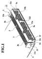
- Fig. 1 is a perspective view of a first connector 1 of the connector structure of the embodiment of the present invention.
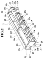
- Fig. 2 is a perspective view of a mechanism member 2.
- Figs. 3 and 4 are perspective and side views showing an assembling operation, respectively.
- Fig. 5 is a side view showing the assembled condition.
- the first connector 1 of the embodiment which is a female connector to be mated with a male connector (not-shown second connector), includes a frame 11 on the front side and a casing 12 (Fig. 3) on the rear side, both of which are made of synthetic resin.
- the frame 11 is in the form of a rectangular frame consisting of a top wall 11a, a bottom wall 11b and left and right sidewalls 11c, 11c.
- the interior of the frame 11 is divided into left and right chambers through a partition wall 11d.
- a pair of extension walls 11e, 11e are formed so as to extend backward from the sidewalls 11c, 11c, respectively.
- Each of the extension walls 11e, 11e is provided, in integral with an exterior face thereof, with a fixing block 13 for thread-engagement with a not-shown screw for fixing the frame 11 on a printed board 4.
- keys 14, 14 are formed to extend up and down of the frame 11. These keys 14, 14 engage with key grooves 24, 24 (mentioned later) formed on the side of the mechanism member 2. Furthermore, an engagement projection 15 is formed on an outer face of each sidewall 11c of the frame 11. The engagement projection 15 is engaged in an engagement hole 25 (also mentioned later) formed on the side of the mechanism member 2.
- Engageably retained in the frame 11 are a plurality of terminals 3 which are soldered to the printed board 4.
- Each terminal 3 is bent in L-shaped manner and has a leading contact 3a retained in the frame 11 to be connected to each mating terminal retained in the mating male connector. While, as shown in Fig. 7A, a rear contact 3b of each terminal 3 penetrates through the printed board 4 and is soldered to a pattern (not shown) on the printed board 4 for electrical connection.
- the casing 12 arranged behind of the frame 11 is provided, on the front side, with an accommodating recess 12a for accommodating the frame 11.
- screw-taps 12b, 12b are formed to accept screws 16 (see Fig. 6) for thread-engagement with the casing 12.
- the accommodating recess 12a of the casing 12 is formed to have a length (width) larger than that of the frame 11.
- a clearance 17 is defined between each sidewalls 11c and the casing 12.
- Respectively inserted into the clearances 17, 17 are a pair of sidewalls 22b, 22b constituting a hood part 22 of the mechanism member 2, which will be described later.
- the accommodating recess 12a is provided, on a rear end thereof, with a flange groove 18 which is longer than the frame 11.
- the hood part 22 of the mechanism member 2 has a pair of flange ribs 28, 28 formed to engage in the flange groove 18. Owing to the engagement of the flange groove 18 with the flange ribs 28, 28, the assembling of the mechanism member 2 to the connector 1 can be guided to prevent the member 2 from disengaging from the connector 1 undesirably.
- the frame 11 is secured on the board 4 by means of the screws through the fixing blocks 13, 13, as shown in Fig. 1.
- the printed board 4 is overlaid with the casing 12 and thereafter, it is fixed on the board 4 by not-shown screws.
- the mechanism member 2 is constituted by a mechanism part 21 for drawing the mating male connector into the connector 1 and the hood part 22 for assembling the mating connector to the connector 1.
- Both of the mechanism part 21 and the hood part 22 are made of synthetic resin, integrally.
- the mechanism part 21 comprises a cylindrical part 23 having a rear opening 23a through which the mating connector is to be inserted, upper and lower slide grooves 30, 30 formed on the cylindrical part 23, a pair of slide members 31, 31 which can slide in the slide grooves 30, 30 reciprocatively and a manipulating lever 32 allowing the respective slide members 31, 31 to reciprocatively slide for engagement or disengagement of the multi-polar female connector 1 with the mating male connector.
- the cylindrical part 23 is in the form of an elongated rectangular cylinder which consists of top and bottom walls 23b, 23c and left and right sidewalls 23d, 23d opposing each other.
- the interior of the cylindrical part 23 is divided into two connector accommodating chambers through a partition wall 23e provide corresponding to the partition wall 11d of the connector 1.
- top wall 23b Integrally standing from the top wall 23b are front and rear walls 23f, 23g between which an upper slide groove 30 is defined. Similarly, a lower slide groove 30 is also defined between the front wall 23f and the rear wall 23g both standing from the bottom wall 23c. Additionally, in the front walls 23f, a plurality of notch guides 23h are formed to introduce guide pins (not shown) of the mating connector into guide grooves 33 in the slide members 31, respectively.
- the guide grooves 33 are formed in the opposite faces of the pair of slide members 31, 31. Each guide groove 33 is inclined to the sliding direction of the slide member 30 at a designated angle.
- the guide grooves 23 are adapted so as to engage with the guide pins of the mating connector, which are introduced through the notch guides 23h. With the sliding movement of the slide members 31, 31 while engaging the guide pins, the mating connector is drawn into the cylindrical part 23.
- the manipulating lever 32 serves to reciprocatively slide the pair of slide members 31, 31 in the opposite directions to each other and has a pivot center hole 32a formed at a center of the base part of the lever 32. Inserted into the pivot center hole 32 is a support shaft 34 which projects from the cylindrical part 23 and through which the manipulating lever 32 is rotatably supported up and down, by the part 23. In the manipulating lever 32, a pair of long holes 32b, 32b are formed on both sides of the pivot center hole 32a. While, the upper and lower slide members 31, 31 are respectively provided with column-shaped attachment bosses 31a, 31a which are inserted into the long holes 32b, 32b in the lever 32, respectively. By rotating the manipulating lever 20 up and down, the upper and lower slide members 31, 31 can be slid in the opposite directions to each other, in reciprocating motion.
- the manipulating lever 32 is provided, on its sidewalls close to the leading end, with rectangular engagement holes 32c for engagement with not-shown engagement protrusions of the cylindrical part 23. With the above structure, it is possible to lock the manipulating lever 32 on the cylindrical part 23.
- the hood part 22 on the front side of the cylindrical part 23 has the interior communicating with the interior of the cylindrical part 23.
- the hood part 22 consists of a top wall 22a and the pair of sidewalls 22b, 22b hanging from left and right ends of the top wall 22a, providing a U-shaped element having an opened lower side. By inserting the frame 11 into the hood part 22 through the above opened lower side, the frame 11 is covered with the hood part 22.
- the hood part 22 is provided, inside both sidewalls 22b, 22b, with the vertical key grooves 24, 24 which engage the keys 14, 14 on the frame 11 of the connector 1, respectively.
- the hood part 22 and the frame 11 can be mutually guided with no lateral slip, thereby completing to put the hood part 22 on the frame 11.
- the hood part 22 is provided, outside both sidewalls 22b, 22b, with the rectangular engagement hole 25, 25 which engage the engagement projections 15, 15 formed on the frame 11, respectively. With this engagement, the hood part 22 can be fixed on the frame 11. In this way, it is possible to assemble the mechanism member 2 to the connector 1.
- the afore-mentioned vertical flange ribs 28, 28 are formed for engagement with the flange groove 18 in the casing 12 of the connector 1.
- the frame 11 of the connector 1 is laid on the printed board 4.
- the contacts 3b of the terminals 3 penetrate respective through-holes (not shown) formed in the printed board 4.
- the frame 11 is secured on the printed board 4.
- the respective contacts 3b of the terminals 3 are connected to a wiring pattern on the printed board 4 by means of solders 5, as shown in Fig. 7A.
- the casing 12 is laid on the printed board 4 and fixed thereon by screws (not shown). In this way, it can be obtained the connector 1 installed on the printed board 4, as shown in Fig. 3.
- the mechanism member 2 is installed on the connector 1 from the upside. That is, as shown with arrows in Figs. 3 and 4, the sidewalls 22b, 22b of the hood 22 are inserted into the clearances 17, 17 each defined between the frame 11 of the connector 1 and the casing 12, from the upside. Consequently, the frame 11 of the connector 1 enters into the hood part 22 through the opened lower side of the hood part 22. At this time, the hood part 22 does slide on the frame 11 downward while the keys 14, 14 on the connector 1 engages with the key grooves 24, 24 of the mechanism member 2, respectively. Therefore, in the sliding movement, the hood part 22 and the frame 11 can mutually slide smooth, without being inclined to each other. In addition, since the above-mentioned assembling does not require to move the mechanism member 2 and the connector 1 in two different directions but requires to slide the mechanism member 2 in one direction (downward), it is possible to carry out the assembling operation with ease.
- the hood part 22 is engaged on the frame 11 with the engagement of the projections 15, 15 with the engagement holes 25, 25, so that the mechanism member 2 is assembled to the connector 1, as shown in Figs. 5 and 6.
- the mechanism member 2 constitutes a part of the housing of the connector 1.
- the flange ribs 28, 28 of the hood part 22 are engaged with the flange groove 18 of the connector 1 in this assembling condition, there is no possibility that the mechanism member 2 disengages from the connector 1 undesirably.
- the mechanism member 2 since the mechanism member 2 is assembled to the connector 1 while the hood part 22 of the mechanism member 2 overlaps the frame 11 of the connector 1, it is unnecessary to put the mechanism part 21 of the mechanism member 2 on the connector 1, whereby the depth of the connector 1 can be reduced. Additionally, since the mechanism part 21 and the connector 1 are provided independent of each other, their configurations are not complicated. Consequently, the sliding resistance of the slide members 31, 31 derived from the deformation during molding etc. can be reduced thereby to realize the smooth drawing of the mating connector into the connector 1.
- the connector 1 and the mechanism member 2 are constituted by different bodies, it is possible to assemble the connector 1 to the printed board 4 under condition that the mechanism member 2 has not been assembled to the connector 1. Therefore, there is no possibility that the mechanism member 2 is deformed by the heat at the time of soldering. Thus, the mechanism member's function to drawn the mating connector is not influenced. Consequently, owing to the provision of such a mechanism member 2, it is possible to accomplish the fitting between the connector 1 and the mating connector, certainly.
- the mechanism member 2 is provided with the hood part 22 which overlaps the frame 11 of the connector 1 in the engagement relationship while the connector 1 and the mechanism member 2 are constituted by different bodies, it is possible to decrease the whole height of the connector structure including the connector 1 and the mechanism member 2
- Figs. 7A and 7B are views for explanation of the above-mentioned effect.
- the male connector may be equipped with the mechanism member in the modification.
- the above keys 14, 14 may be formed on the mechanism member 2 while providing the connector 1 with the key grooves 24, 24.
- the above engagement projections 15, 15 may be formed on the mechanism member 2 while providing the connector 1 with the engagement holes 25, 25.
Landscapes
- Coupling Device And Connection With Printed Circuit (AREA)
- Details Of Connecting Devices For Male And Female Coupling (AREA)
Applications Claiming Priority (2)
| Application Number | Priority Date | Filing Date | Title |
|---|---|---|---|
| JP7784098 | 1998-03-25 | ||
| JP07784098A JP4149553B2 (ja) | 1998-03-25 | 1998-03-25 | コネクタ構造及びコネクタの組付方法 |
Publications (3)
| Publication Number | Publication Date |
|---|---|
| EP0948094A2 true EP0948094A2 (fr) | 1999-10-06 |
| EP0948094A3 EP0948094A3 (fr) | 2003-01-22 |
| EP0948094B1 EP0948094B1 (fr) | 2005-11-30 |
Family
ID=13645257
Family Applications (1)
| Application Number | Title | Priority Date | Filing Date |
|---|---|---|---|
| EP99105042A Expired - Lifetime EP0948094B1 (fr) | 1998-03-25 | 1999-03-22 | Structure de connecteur et méthode d'assemblage de connecteurs |
Country Status (4)
| Country | Link |
|---|---|
| US (1) | US6183276B1 (fr) |
| EP (1) | EP0948094B1 (fr) |
| JP (1) | JP4149553B2 (fr) |
| DE (1) | DE69928591T2 (fr) |
Families Citing this family (6)
| Publication number | Priority date | Publication date | Assignee | Title |
|---|---|---|---|---|
| USD459309S1 (en) | 2000-12-15 | 2002-06-25 | Sumitomo Wiring Systems, Ltd. | Electrical connector |
| USD460048S1 (en) | 2001-01-12 | 2002-07-09 | Japan Aviation Electronics Industry, Limited | Electrical connector |
| SG128501A1 (en) * | 2005-06-15 | 2007-01-30 | Mea Technologies Pte Ltd | Connector for printed wiring board |
| US7347704B2 (en) * | 2006-03-01 | 2008-03-25 | Sumitomo Wiring Systems, Ltd. | Connector |
| JP4153541B2 (ja) * | 2006-09-13 | 2008-09-24 | タイコエレクトロニクスアンプ株式会社 | レバー式電気コネクタ |
| JP5961493B2 (ja) * | 2012-09-04 | 2016-08-02 | 矢崎総業株式会社 | コネクタ装置 |
Family Cites Families (7)
| Publication number | Priority date | Publication date | Assignee | Title |
|---|---|---|---|---|
| JP3134503B2 (ja) | 1992-06-19 | 2001-02-13 | 松下電器産業株式会社 | スイッチ実装構造 |
| JPH06267610A (ja) | 1993-03-11 | 1994-09-22 | Amp Japan Ltd | カム作動型コネクタ |
| JP2799490B2 (ja) | 1995-02-16 | 1998-09-17 | モレックス インコーポレーテッド | カム機構を有する電気コネクタ |
| JP3086656B2 (ja) * | 1996-06-24 | 2000-09-11 | 矢崎総業株式会社 | コネクタの嵌合構造 |
| JP3442577B2 (ja) * | 1996-06-27 | 2003-09-02 | 矢崎総業株式会社 | フードアッシーのコネクタへの組付方法および同組付構造 |
| JP3457146B2 (ja) * | 1997-06-06 | 2003-10-14 | 矢崎総業株式会社 | コネクタの係止構造 |
| US5938458A (en) * | 1998-06-17 | 1999-08-17 | Molex Incorporated | Lever type electrical connector |
-
1998
- 1998-03-25 JP JP07784098A patent/JP4149553B2/ja not_active Expired - Fee Related
-
1999
- 1999-03-22 EP EP99105042A patent/EP0948094B1/fr not_active Expired - Lifetime
- 1999-03-22 DE DE69928591T patent/DE69928591T2/de not_active Expired - Lifetime
- 1999-03-23 US US09/274,974 patent/US6183276B1/en not_active Expired - Lifetime
Also Published As
| Publication number | Publication date |
|---|---|
| DE69928591T2 (de) | 2006-08-10 |
| JPH11273804A (ja) | 1999-10-08 |
| JP4149553B2 (ja) | 2008-09-10 |
| EP0948094A3 (fr) | 2003-01-22 |
| US6183276B1 (en) | 2001-02-06 |
| EP0948094B1 (fr) | 2005-11-30 |
| DE69928591D1 (de) | 2006-01-05 |
Similar Documents
| Publication | Publication Date | Title |
|---|---|---|
| US5425650A (en) | Inclined engagement prevention structure for connector | |
| JP2553115Y2 (ja) | コネクタ | |
| US5980325A (en) | Micro miniature electrical connector and method of manufacture | |
| US5947775A (en) | Connector | |
| US5683272A (en) | Pressure-contact connector | |
| EP1265317A2 (fr) | Contact et connecteur électrique avec un tel contact | |
| US6056582A (en) | Lever fitting connector | |
| US6767239B2 (en) | Connector with interengageable rib and groove for guiding connection and a method of assembling such a connector | |
| EP0843386A1 (fr) | Connecteur à levier | |
| US7198496B2 (en) | Lever type connector | |
| US5702265A (en) | Connector structure | |
| JPH10112355A (ja) | 電気コネクタのガタ防止構造 | |
| US6887098B1 (en) | Combined electrical connector | |
| US5730617A (en) | Guide structure for an electronic unit | |
| US7402069B2 (en) | Connector | |
| EP0948094B1 (fr) | Structure de connecteur et méthode d'assemblage de connecteurs | |
| US6213794B1 (en) | Lever fitting-type connector | |
| KR100615894B1 (ko) | 커넥터의 하우징 및 이를 이용한 커넥터 | |
| JPH0917485A (ja) | リヤホルダー付きコネクタ | |
| JPH09245869A (ja) | 端子係止具付きコネクタ | |
| KR100344897B1 (ko) | 커넥터 결합용 접속부 구조 | |
| US6213792B1 (en) | Connector fitting structure | |
| EP1209775A2 (fr) | Connecteur à jack modulaire | |
| EP1172895A1 (fr) | Connecteur | |
| JPH08287990A (ja) | コネクタ |
Legal Events
| Date | Code | Title | Description |
|---|---|---|---|
| PUAI | Public reference made under article 153(3) epc to a published international application that has entered the european phase |
Free format text: ORIGINAL CODE: 0009012 |
|
| 17P | Request for examination filed |
Effective date: 19990322 |
|
| AK | Designated contracting states |
Kind code of ref document: A2 Designated state(s): AT BE CH CY DE DK ES FI FR GB GR IE IT LI LU MC NL PT SE |
|
| AX | Request for extension of the european patent |
Free format text: AL;LT;LV;MK;RO;SI |
|
| PUAL | Search report despatched |
Free format text: ORIGINAL CODE: 0009013 |
|
| AK | Designated contracting states |
Kind code of ref document: A3 Designated state(s): AT BE CH CY DE DK ES FI FR GB GR IE IT LI LU MC NL PT SE |
|
| AX | Request for extension of the european patent |
Free format text: AL;LT;LV;MK;RO;SI |
|
| AKX | Designation fees paid |
Designated state(s): DE FR GB |
|
| 17Q | First examination report despatched |
Effective date: 20040127 |
|
| GRAP | Despatch of communication of intention to grant a patent |
Free format text: ORIGINAL CODE: EPIDOSNIGR1 |
|
| GRAS | Grant fee paid |
Free format text: ORIGINAL CODE: EPIDOSNIGR3 |
|
| GRAA | (expected) grant |
Free format text: ORIGINAL CODE: 0009210 |
|
| RIC1 | Information provided on ipc code assigned before grant |
Ipc: 7H 01R 12/20 B Ipc: 7H 01R 13/64 B Ipc: 7H 01R 13/629 A |
|
| AK | Designated contracting states |
Kind code of ref document: B1 Designated state(s): DE FR GB |
|
| REG | Reference to a national code |
Ref country code: GB Ref legal event code: FG4D |
|
| REF | Corresponds to: |
Ref document number: 69928591 Country of ref document: DE Date of ref document: 20060105 Kind code of ref document: P |
|
| ET | Fr: translation filed | ||
| PLBE | No opposition filed within time limit |
Free format text: ORIGINAL CODE: 0009261 |
|
| STAA | Information on the status of an ep patent application or granted ep patent |
Free format text: STATUS: NO OPPOSITION FILED WITHIN TIME LIMIT |
|
| 26N | No opposition filed |
Effective date: 20060831 |
|
| PGFP | Annual fee paid to national office [announced via postgrant information from national office to epo] |
Ref country code: FR Payment date: 20130325 Year of fee payment: 15 Ref country code: GB Payment date: 20130320 Year of fee payment: 15 Ref country code: DE Payment date: 20130320 Year of fee payment: 15 |
|
| REG | Reference to a national code |
Ref country code: DE Ref legal event code: R119 Ref document number: 69928591 Country of ref document: DE |
|
| GBPC | Gb: european patent ceased through non-payment of renewal fee |
Effective date: 20140322 |
|
| REG | Reference to a national code |
Ref country code: FR Ref legal event code: ST Effective date: 20141128 |
|
| PG25 | Lapsed in a contracting state [announced via postgrant information from national office to epo] |
Ref country code: DE Free format text: LAPSE BECAUSE OF NON-PAYMENT OF DUE FEES Effective date: 20141001 Ref country code: FR Free format text: LAPSE BECAUSE OF NON-PAYMENT OF DUE FEES Effective date: 20140331 Ref country code: GB Free format text: LAPSE BECAUSE OF NON-PAYMENT OF DUE FEES Effective date: 20140322 |
|
| REG | Reference to a national code |
Ref country code: DE Ref legal event code: R119 Ref document number: 69928591 Country of ref document: DE Effective date: 20141001 |