EP0948113A2 - Verfahren und Vorrichtung zum Betrieb von Energieverbrauchseinheiten - Google Patents
Verfahren und Vorrichtung zum Betrieb von Energieverbrauchseinheiten Download PDFInfo
- Publication number
- EP0948113A2 EP0948113A2 EP99104814A EP99104814A EP0948113A2 EP 0948113 A2 EP0948113 A2 EP 0948113A2 EP 99104814 A EP99104814 A EP 99104814A EP 99104814 A EP99104814 A EP 99104814A EP 0948113 A2 EP0948113 A2 EP 0948113A2
- Authority
- EP
- European Patent Office
- Prior art keywords
- central unit
- central
- unit
- energy consumption
- units
- Prior art date
- Legal status (The legal status is an assumption and is not a legal conclusion. Google has not performed a legal analysis and makes no representation as to the accuracy of the status listed.)
- Withdrawn
Links
Images
Classifications
-
- H—ELECTRICITY
- H02—GENERATION; CONVERSION OR DISTRIBUTION OF ELECTRIC POWER
- H02J—ELECTRIC POWER NETWORKS; CIRCUIT ARRANGEMENTS OR SYSTEMS FOR SUPPLYING OR DISTRIBUTING ELECTRIC POWER; SYSTEMS FOR STORING ELECTRIC ENERGY
- H02J13/00—Circuit arrangements for providing remote monitoring or remote control of equipment in a power distribution network
- H02J13/13—Circuit arrangements for providing remote monitoring or remote control of equipment in a power distribution network characterised by the transmission of data to equipment in the power network
- H02J13/1331—Circuit arrangements for providing remote monitoring or remote control of equipment in a power distribution network characterised by the transmission of data to equipment in the power network using wireless data transmission
-
- H—ELECTRICITY
- H02—GENERATION; CONVERSION OR DISTRIBUTION OF ELECTRIC POWER
- H02J—ELECTRIC POWER NETWORKS; CIRCUIT ARRANGEMENTS OR SYSTEMS FOR SUPPLYING OR DISTRIBUTING ELECTRIC POWER; SYSTEMS FOR STORING ELECTRIC ENERGY
- H02J13/00—Circuit arrangements for providing remote monitoring or remote control of equipment in a power distribution network
- H02J13/12—Monitoring network conditions, e.g. electrical magnitudes or operational status
-
- H—ELECTRICITY
- H02—GENERATION; CONVERSION OR DISTRIBUTION OF ELECTRIC POWER
- H02J—ELECTRIC POWER NETWORKS; CIRCUIT ARRANGEMENTS OR SYSTEMS FOR SUPPLYING OR DISTRIBUTING ELECTRIC POWER; SYSTEMS FOR STORING ELECTRIC ENERGY
- H02J13/00—Circuit arrangements for providing remote monitoring or remote control of equipment in a power distribution network
- H02J13/13—Circuit arrangements for providing remote monitoring or remote control of equipment in a power distribution network characterised by the transmission of data to equipment in the power network
- H02J13/1321—Circuit arrangements for providing remote monitoring or remote control of equipment in a power distribution network characterised by the transmission of data to equipment in the power network using a wired telecommunication network or a data transmission bus
- H02J13/1323—Circuit arrangements for providing remote monitoring or remote control of equipment in a power distribution network characterised by the transmission of data to equipment in the power network using a wired telecommunication network or a data transmission bus using optical fibres
-
- H—ELECTRICITY
- H02—GENERATION; CONVERSION OR DISTRIBUTION OF ELECTRIC POWER
- H02J—ELECTRIC POWER NETWORKS; CIRCUIT ARRANGEMENTS OR SYSTEMS FOR SUPPLYING OR DISTRIBUTING ELECTRIC POWER; SYSTEMS FOR STORING ELECTRIC ENERGY
- H02J2107/00—Circuit arrangements for communication specially adapted for monitoring, managing or controlling operation of power networks remotely
- H02J2107/40—Circuit arrangements for communication specially adapted for monitoring, managing or controlling operation of power networks remotely using simultaneously two or more different transmission means
-
- Y—GENERAL TAGGING OF NEW TECHNOLOGICAL DEVELOPMENTS; GENERAL TAGGING OF CROSS-SECTIONAL TECHNOLOGIES SPANNING OVER SEVERAL SECTIONS OF THE IPC; TECHNICAL SUBJECTS COVERED BY FORMER USPC CROSS-REFERENCE ART COLLECTIONS [XRACs] AND DIGESTS
- Y02—TECHNOLOGIES OR APPLICATIONS FOR MITIGATION OR ADAPTATION AGAINST CLIMATE CHANGE
- Y02E—REDUCTION OF GREENHOUSE GAS [GHG] EMISSIONS, RELATED TO ENERGY GENERATION, TRANSMISSION OR DISTRIBUTION
- Y02E60/00—Enabling technologies; Technologies with a potential or indirect contribution to GHG emissions mitigation
-
- Y—GENERAL TAGGING OF NEW TECHNOLOGICAL DEVELOPMENTS; GENERAL TAGGING OF CROSS-SECTIONAL TECHNOLOGIES SPANNING OVER SEVERAL SECTIONS OF THE IPC; TECHNICAL SUBJECTS COVERED BY FORMER USPC CROSS-REFERENCE ART COLLECTIONS [XRACs] AND DIGESTS
- Y04—INFORMATION OR COMMUNICATION TECHNOLOGIES HAVING AN IMPACT ON OTHER TECHNOLOGY AREAS
- Y04S—SYSTEMS INTEGRATING TECHNOLOGIES RELATED TO POWER NETWORK OPERATION, COMMUNICATION OR INFORMATION TECHNOLOGIES FOR IMPROVING THE ELECTRICAL POWER GENERATION, TRANSMISSION, DISTRIBUTION, MANAGEMENT OR USAGE, i.e. SMART GRIDS
- Y04S10/00—Systems supporting electrical power generation, transmission or distribution
- Y04S10/30—State monitoring, e.g. fault, temperature monitoring, insulator monitoring, corona discharge
-
- Y—GENERAL TAGGING OF NEW TECHNOLOGICAL DEVELOPMENTS; GENERAL TAGGING OF CROSS-SECTIONAL TECHNOLOGIES SPANNING OVER SEVERAL SECTIONS OF THE IPC; TECHNICAL SUBJECTS COVERED BY FORMER USPC CROSS-REFERENCE ART COLLECTIONS [XRACs] AND DIGESTS
- Y04—INFORMATION OR COMMUNICATION TECHNOLOGIES HAVING AN IMPACT ON OTHER TECHNOLOGY AREAS
- Y04S—SYSTEMS INTEGRATING TECHNOLOGIES RELATED TO POWER NETWORK OPERATION, COMMUNICATION OR INFORMATION TECHNOLOGIES FOR IMPROVING THE ELECTRICAL POWER GENERATION, TRANSMISSION, DISTRIBUTION, MANAGEMENT OR USAGE, i.e. SMART GRIDS
- Y04S40/00—Systems for electrical power generation, transmission, distribution or end-user application management characterised by the use of communication or information technologies, or communication or information technology specific aspects supporting them
- Y04S40/12—Systems for electrical power generation, transmission, distribution or end-user application management characterised by the use of communication or information technologies, or communication or information technology specific aspects supporting them characterised by data transport means between the monitoring, controlling or managing units and monitored, controlled or operated electrical equipment
- Y04S40/124—Systems for electrical power generation, transmission, distribution or end-user application management characterised by the use of communication or information technologies, or communication or information technology specific aspects supporting them characterised by data transport means between the monitoring, controlling or managing units and monitored, controlled or operated electrical equipment using wired telecommunication networks or data transmission busses
-
- Y—GENERAL TAGGING OF NEW TECHNOLOGICAL DEVELOPMENTS; GENERAL TAGGING OF CROSS-SECTIONAL TECHNOLOGIES SPANNING OVER SEVERAL SECTIONS OF THE IPC; TECHNICAL SUBJECTS COVERED BY FORMER USPC CROSS-REFERENCE ART COLLECTIONS [XRACs] AND DIGESTS
- Y04—INFORMATION OR COMMUNICATION TECHNOLOGIES HAVING AN IMPACT ON OTHER TECHNOLOGY AREAS
- Y04S—SYSTEMS INTEGRATING TECHNOLOGIES RELATED TO POWER NETWORK OPERATION, COMMUNICATION OR INFORMATION TECHNOLOGIES FOR IMPROVING THE ELECTRICAL POWER GENERATION, TRANSMISSION, DISTRIBUTION, MANAGEMENT OR USAGE, i.e. SMART GRIDS
- Y04S40/00—Systems for electrical power generation, transmission, distribution or end-user application management characterised by the use of communication or information technologies, or communication or information technology specific aspects supporting them
- Y04S40/12—Systems for electrical power generation, transmission, distribution or end-user application management characterised by the use of communication or information technologies, or communication or information technology specific aspects supporting them characterised by data transport means between the monitoring, controlling or managing units and monitored, controlled or operated electrical equipment
- Y04S40/126—Systems for electrical power generation, transmission, distribution or end-user application management characterised by the use of communication or information technologies, or communication or information technology specific aspects supporting them characterised by data transport means between the monitoring, controlling or managing units and monitored, controlled or operated electrical equipment using wireless data transmission
Definitions
- the present invention relates to a method to support operation of energy consumption units with several energy consumption points. Furthermore, the invention relates to a device for performing the method and a unit for operating energy consumption points.
- Energy consumption units in the sense of the present invention for example buildings, industrial buildings, energy-consuming systems and the like, the different energy consumption points and different Have numbers of the same.
- the different energies are connected to one Consumption unit introduced and from a substantially central location the consumption points distributed. If you see a building unit, for example a power supply line arrives at a central location, at others Places can be gas lines, generally fuel lines, heat lines and the like are supplied.
- the consumption units are currently recorded at central points by the Energy suppliers read or communicated to them and the energy consumption settled.
- energy consumers are not interested in final energy, So electricity, natural gas and the like, but only on the use of it resulting quantities, for example light, heat, cold, power and the like.
- the production and delivery of energy should be as close as possible the needs are adjusted or vice versa the consumption of economic favorable or reasonable provider times.
- the operation includes the detection, Management and, if necessary, control.
- the present invention is based on the object of specifying a method for supporting the operation of energy consumption units which, with simple means, has a very effective means of improving the process of energy supply and broadly broadening the possibilities of energy use.
- the invention proposes a method for supporting the operation of energy consumption units with a plurality of energy consumption points, different evaluation, control and query methods being used at the same time, a central unit assigned to an energy consumption unit being accessible externally via at least one remote communication unit and is directly or indirectly connected to at least some of the energy consumption points internally and selectively carries out a data transfer by the central unit and records operating data in consideration of various methods, converts it into a predetermined protocol and makes it available for processing and / or transmission or via the remote Control instructions received communication system are directed to the individual energy consumption points.
- the invention enables central operating data acquisition and processing suggested which, using today's electronic capabilities a significant support in the supply and supply of energy represents.
- the operating data for Remote transmission provided.
- the on a given protocol, a So-called communication protocol, converted data is processed according to a Proposed the invention for remote access.
- the central unit can have a communication line, for example a telephone line, a radio line, one designed for communication Evaluate the power supply line or the like and Detect on the input side whether, for example, meter readings have been carried out or receive control commands.
- the central unit can then under Use of the channel and intended for the respective application Tax rate process the received command, for example one Query the meter reading and transfer the result back or a control command to exercise.
- the central unit is able to handle a large number integrate conventional and customary processes and systems and over to make only one communication line usable.
- the central unit is advantageously also connected to consumption units or Consumers related sensors connected.
- the central unit connected to consumption units or actuators related to consumption points become.
- the recorded operating data can be used to query the status be put together. This makes it possible to control from a control center To request the status of different sensors or actuators.
- sensors and / or actuators in the range of Energy tapping points are arranged. Switchable sockets, Line valves and the like are used.
- sensors and / or actuators energy-consuming devices can be arranged.
- Such remotely controllable Sensors or actuators at energy tapping points and / or energy-consuming devices make the housing technology one remote management matter, in terms of security, optimal Energy use, economy and the like can be optimized.
- Access control units can be connected to the central unit.
- This solution represents an improvement or broadening of the range of services, because areas can be secured via access control units, and against unauthorized access, burglary and the like.
- connections can be considered as connections, namely telephone network, powerline, radio, radio frequencies, broadband cable, Light guides and the like. Can also use mobile phone networks and so on be used.
- Energy consumption is automatically read and billed promptly, Data and market analyzes are carried out, order services be handled, a load management installed, a maintenance management, fault management through to external fault analysis and Work control and the like can be performed.
- Measures such as signaling, observation or checking, reading, Measurement, switching, possibly also programming and in particular Control below.
- the invention also provides a system for carrying out a Process for supporting the operation of energy consumption units of the described type proposed, which comprises at least one central unit, which in turn have at least one processor unit, at least one memory unit, at least one communication interface and at least one Has data interface and directly or indirectly with energy consumption points for data acquisition and with at least one control center for data processing is connectable after their conversion.
- the system according to the invention is based on in the range of Central units arranged as energy consumption units Communication interface in which on the one hand input and / or Output data are passed through with or without processing, on the other hand Messages, commands and the like in the context of a data-based Communication.
- the central unit advantageously has a pulse interface according to a further advantageous proposal of the invention also an interface for Optical fiber.
- the central unit advantageously has one Telephone communication interface on.
- the central unit is also included Connectable energy meters.
- the Central unit with sensors and / or actuators in the range of Energy tapping points and / or energy consuming devices can be connected be. This can be done from a central control center via the Communication interface accessing data or transmitting commands, one full management of an energy consumption unit, for example one Building.
- the central control center can directly with Central units can be connected or with intermediate centers, which in turn again combine a large number of central units.
- the central unit is connected to at least one interface for card reading units, for example, to be able to carry out access controls. Furthermore can the central unit with display units as well as with input and Output devices can be connected to data entry, data output and To enable data display.
- the central unit can be provided with interfaces to for example acoustic signals, video signals or other signals from Recording, processing units and the like to record, prepare and for To make available.
- the system provided by the invention is used for the construction and Maintenance of remote-controlled operation of energy consumption units using simple and economically available means.
- the invention protects a central unit for use in the System according to the invention according to the inventive method, comprising at least one processor unit, at least one memory and each at least one interface for communication and data.
- the present invention is based on the finding that energy consumption on the one hand represents an environmental impact, on the other hand the market of Energy suppliers no longer provide any noteworthy growth. Out of it the result is that the energy market is optimized from an economic point of view must become. On the one hand, this includes improved delivery and use of energy and on the other hand improving services around the Energy supply.
- the core of the invention is a central unit, an energy consumption unit assigned.
- An energy consumption unit for example a building, has a variety of energy consumption points.
- Energy consumption points are Sockets, cable ends, transformers, converter units or radiating units, for example for the supply of district heating. To but also include plants in the industrial sector.
- the central unit can be used for a large number of measures, for example for remote meter reading transmission, which means that energy consumption is automatically read and billed promptly and the data is also available for a market analysis.
- the supply of fuel in price-optimized time phases, load management, maintenance and fault management as well as remote management for customer systems can also be provided.
- This requires a communication interface in order to be able to communicate with the central unit from a control center, and a data interface in order to be able to obtain or output data as a function of the incoming commands or the incoming queries.
- the central unit can be used for extensive measures, whereby the processing of malfunction reports, i.e.
- the information system as a whole is made up of a central control system, a communication unit in the area of the central unit and connections to the most diverse consumption units. It is preferred to to think of a client-server technology, taking dynamic data of the operating systems are to be operated, observed and monitored.
- a Another aspect of the invention is the so-called concentrator technology, one Many central units are networked locally and this network one Intermediate center, a concentrator is assigned. The concentrators in turn are connected to the control center.
- a particular aspect of the invention is the provision of sensors and if necessary also actuators in the area of consumers. You can Sensors and actuators at consumption points, at switches, on devices and the like can be arranged.
- the dialogue-capable energy consumers are thus also remotely controllable via the corresponding central unit.
- This Remote control can be used, one from a consumer perspective maintenance-free operation and maintenance-free provision of the desired To ensure consumption results, i.e. light, heat, cold and the like, without the consumer worrying about each Implementations of the energies must take care.
- Communication network can be used. In the communication area outside the energy consumption units or the customer systems with the invention also proposed the use of the power line. Here are both Communication on low voltage level (400 volts) as well as on the Medium voltage level (20 kV) provided.
- the central unit is with a wide variety of consumption meters, so Electricity meters, gas meters, hot water meters and the like connect. Corresponding data acquisition devices can be used on the meters are arranged, which are digitally connected to the central unit. Also Analog recordings and subsequent digitization are conceivable. Counter interfaces lead to data inputs into the central unit, which follow Transformation for transmission to the control center are available, for example by radio, by mobile phone network, by telephone network, by power line and the same. Services can be billed in the control center. Statistics, pure visualizations and similar applications.
- the main process in the central unit is the conversion of the input data into one Transmission protocol, if necessary also the intermediate storage.
- the central unit has a memory for both has certified as well as non-certified data, a synchronizable Has time base and clock, a self-dialing function, for example in the event of alarms or alarm conditions, a two-way circuit for communication, one if necessary, additional power supply in the event of a power failure, self-monitoring and self-diagnosis, priority detection and Possibility of modem approval, radio interference suppression and remote parameterization.
- a is particularly desirable standardized housing, for example around the central unit according to a counter field To be able to arrange DIN 43870.
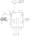
- the central unit designated 1 in FIG. 1, also called KomBox, is shown in a housing 2 preferably arranged according to DIN and has one Processor unit / memory unit 3, a display unit 4 and Interface areas 5, 6, 7 and 8.
- the representation in Figure 1 is not Chosen according to technically exact points of view, but according to points of view the formal clarity.
- the central unit 1 is via the data interface 5 by means of a line 23 connected to an electricity consumption meter.
- the central unit receives data that it stores in a consumption meter appropriate protocol transforms and stores or for communication provides.
- a counter control 22 can also be used by the central unit Control of the counter 21 can be controlled.
- the communication interface 6 is used, for example, for Remote meter transmission, tariff control, load profile detection, the Remote parameterization, the implementation in the event of self-malfunction, the Time synchronization, priority detection and the like.
- the Remote transmission can take place via any medium, for example via the telephone network, through power lines, radio, radio frequencies, broadband cables, Optical fibers and the like. Mobile phone networks are also included.
- control center 9 also called the control center carried out, examples being the visualization 10 which Billing 11, services 12 or statistics 13.
- Another interface 7 is used for input and output of data, for example Counts, tariff control, synchronization, alarms and messages and the like.
- the interface 8 is used, for example, for connection to sensors 14, actuators 15, other counters 16 and the like by means of the LON method (Local Operating Network) or similar procedures.
- LON method Local Operating Network
- conventional Bus systems, fiber optic cables or pulse interfaces also used internally become.
Landscapes
- Engineering & Computer Science (AREA)
- Power Engineering (AREA)
- Selective Calling Equipment (AREA)
- Power Sources (AREA)
Abstract
Description
- Fig. 1
- eine schematische Darstellung einer Zentraleinheit und ihrer Einbindung in das System
- 1
- Zentraleinheit
- 2
- Gehäuse
- 3
- Prozessor/Speicher
- 4
- Anzeigeeinheit
- 5
- Datenschnittstelle
- 6
- Kommunikationsschnittstelle
- 7
- Schnittstelle
- 8
- Schnittstelle
- 9
- Leitstelle
- 10
- Visualisierung
- 11
- Abrechnung
- 12
- Dienstleistung
- 13
- Statistik
- 14
- Sensoren
- 15
- Aktoren
- 16
- andere Zähler
- 17
- Zählimpulse
- 18
- Tarifsteuerung
- 19
- Synchronisation
- 20
- Alarm und Meldungen
- 21
- Zähler
- 22
- Steuerungsleitung
- 23
- Kommunikationsleitung
Claims (25)
- Verfahren zur Unterstützung des Betriebs von Energieverbrauchseinheiten mit mehreren Energieverbrauchsstellen, wobei gleichzeitig verschiedene Auswerte-, Ansteuerungs- und Abfrageverfahren eingesetzt werden, wobei eine einer Energieverbrauchseinheit zugeordnete Zentraleinheit nach Außerhalb über wenigstens eine Fern-Kommunikationseinheit zugänglich und nach Innen mit wenigstens einem Teil der Energieverbrauchsstellen direkt oder indirekt verbunden ist und von der Zentraleinheit selektiv ein Datentransfer durchgeführt und unter Berücksichtigung verschiedener Verfahren Betriebsdaten erfaßt, in ein vorgegebenen Protokoll konvertiert und zur Verarbeitung und/oder Übertragung bereit gestellt bzw. über die Fern-Kommunikationsanlage empfangene Steueranweisungen an die einzelnen Energieverbrauchsstellen geleitet werden.
- Verfahren nach Anspruch 1, dadurch gekennzeichnet, daß die Zentraleinheit mit Energieverbrauchszählern verbunden wird.
- Verfahren nach einem der vorhergehenden Ansprüche, dadurch gekennzeichnet, daß die Zentraleinheit mit verbrauchsbezogenen Sensoren zur Aufnahme von Sensordaten verbunden wird.
- Verfahren nach einem der vorhergehenden Ansprüche, dadurch gekennzeichnet, daß die Zentraleinheit mit Aktoren zur Ansteuerung verbunden wird.
- Verfahren nach einem der Ansprüche 3 oder 4, dadurch gekennzeichnet, daß über die Zentraleinheit Statusabfragen der Sensoren und/oder Aktoren durchgeführt werden.
- Verfahren nach wenigstens einem der Ansprüche 3 bis 5, dadurch gekennzeichnet, daß die Sensoren und/oder Aktoren an Energieentnahmestellen angeordnet werden.
- Verfahren nach wenigstens einem der Ansprüche 3 bis 5, dadurch gekennzeichnet, daß die Sensoren und/oder Aktoren an energieverbrauchenden Geräten angeordnet werden.
- Verfahren nach wenigstens einem der vorhergehenden Ansprüche, dadurch gekennzeichnet, daß die Zentraleinheit zur Durchführung von Zugangskontrollen eingesetzt wird.
- Verfahren nach einem der vorhergehenden Ansprüche, dadurch gekennzeichnet, daß mehrere Zentraleinheiten mit wenigstens einer Zwischenzentrale zu einem zentralen Netz verbunden werden.
- Verfahren nach einem der vorhergehenden Ansprüche, dadurch gekennzeichnet, daß eine Vielzahl von Zentraleinheiten mit oder ohne Zwischenzentralen mit einem zentralen Leitstand verbunden werden.
- System zur Durchführung eines Verfahrens zur Unterstützung des Betriebs von Energieverbrauchseinheiten mit mehreren Energieverbrauchsstellen, umfassend wenigstens eine Zentraleinheit mit wenigstens einer Prozessoreinheit, wenigstens einer Speichereinheit, wenigstens einer Kommunikationsschnittstelle und wenigstens einer Datenschnittstelle, über welche die Zentraleinheit mit Energieverbrauchsstellen direkt oder indirekt verbunden ist, wobei die Zentraleinheit über die wenigstens eine Kommunikationsschnittstelle mit einer Leitstelle verbindbar ist.
- System nach Anspruch 11, dadurch gekennzeichnet, daß die Zentraleinheit eine Impulsschnittstelle aufweist.
- System nach einem der Ansprüche 11 oder 12, dadurch gekennzeichnet, daß die Zentraleinheit wenigstens eine Lichtwellenleiter-Schnittstelle aufweist.
- System nach einem der Ansprüche 11 bis 13, dadurch gekennzeichnet, daß die Kommunikationsschnittstelle zur Nutzung von Fernsprechkommunikationseinheiten ausgelegt ist.
- System nach einem der Ansprüche 11 bis 14, dadurch gekennzeichnet, daß eine Zentraleinheit mit Energieverbrauchszählern verbindbar ist.
- System nach einem der Ansprüche 11 bis 15, dadurch gekennzeichnet, daß eine Zentraleinheit mit verbrauchsbezogenen Sensoren verbindbar ist.
- System nach einem der Ansprüche 11 bis 16, dadurch gekennzeichnet, daß eine Zentraleinheit mit Aktoren verbindbar ist.
- System nach einem der Ansprüche 16 oder 17, dadurch gekennzeichnet, daß Sensoren und/oder Aktoren an Energieentnahmestellen angeordnet sind.
- System nach einem der Ansprüche 16 oder 17, dadurch gekennzeichnet, daß Sensoren und/oder Aktoren an energieverbrauchenden Geräten angeordnet sind.
- System nach einem der Ansprüche 11 bis 19, dadurch gekennzeichnet, daß mehrere Zentraleinheiten mit Zwischenzentraleinheiten verbunden sind.
- System nach Anspruch 20, dadurch gekennzeichnet, daß eine Vielzahl von Zentraleinheiten und/oder Zwischenzentraleinheiten mit einer zentralen Leitstelle verbunden sind.
- System nach einem der Ansprüche 11 bis 21, dadurch gekennzeichnet, daß die Zentraleinheit mit einer Kartenleseeinheit verbunden ist.
- System nach einem der Ansprüche 11 bis 22, dadurch gekennzeichnet, daß die Zentraleinheit mit wenigstens einer Anzeigeeinheit verbunden ist.
- System nach einem der Ansprüche 11 bis 23, dadurch gekennzeichnet, daß die Zentraleinheit ein normiertes Gehäuse aufweist.
- Zentraleinheit zur Unterstützung des Betriebs von Energieverbrauchseinheiten mit mehreren Energieverbrauchsstellen, umfassend wenigstens eine Prozessoreinheit, wenigstens eine Speichereinheit, wenigstens eine Kommunikationsschnittstelle und wenigstens eine Datenschnittstelle, wobei die Zentraleinheit direkt oder indirekt über die Datenschnittstelle mit Energieverbrauchsstellen und über die Kommunikationsschnittstelle mit wenigstens einer Leitstelle verbindbar ist.
Applications Claiming Priority (2)
| Application Number | Priority Date | Filing Date | Title |
|---|---|---|---|
| DE19815169 | 1998-04-04 | ||
| DE19815169A DE19815169A1 (de) | 1998-04-04 | 1998-04-04 | Verfahren und Vorrichtung zum Betrieb von Energieverbrauchseinheiten |
Publications (2)
| Publication Number | Publication Date |
|---|---|
| EP0948113A2 true EP0948113A2 (de) | 1999-10-06 |
| EP0948113A3 EP0948113A3 (de) | 2000-07-05 |
Family
ID=7863614
Family Applications (1)
| Application Number | Title | Priority Date | Filing Date |
|---|---|---|---|
| EP99104814A Withdrawn EP0948113A3 (de) | 1998-04-04 | 1999-03-11 | Verfahren und Vorrichtung zum Betrieb von Energieverbrauchseinheiten |
Country Status (2)
| Country | Link |
|---|---|
| EP (1) | EP0948113A3 (de) |
| DE (1) | DE19815169A1 (de) |
Cited By (5)
| Publication number | Priority date | Publication date | Assignee | Title |
|---|---|---|---|---|
| DE102004035194A1 (de) * | 2004-07-21 | 2006-02-16 | Görlitz Ag | Verfahren zur Weiterleitung von Zeitinformationen |
| EP1936454A1 (de) * | 2006-12-22 | 2008-06-25 | Siemens Aktiengesellschaft | Steuereinheit zur Steuerung mindestens eines Verbrauchers |
| DE102009048935A1 (de) * | 2009-07-28 | 2011-02-10 | Abb Ag | Busfähiges Steuerungsgerät zur Steuerung mindestens eines Verbrauchers |
| CN102830681A (zh) * | 2012-06-21 | 2012-12-19 | 上海擎云物联网有限公司 | 一种远程电能耗数据的监控方法及其配套装置 |
| EP2105711A3 (de) * | 2008-03-28 | 2013-10-23 | Abb Ag | Anordnung zur Energieerfassung und Anzeige in der Gebäudesystemtechnik |
Families Citing this family (2)
| Publication number | Priority date | Publication date | Assignee | Title |
|---|---|---|---|---|
| DE20101450U1 (de) | 2001-01-27 | 2001-04-05 | EFB-Elektronik M.Stechmann GmbH, 65479 Raunheim | Bewegliche Einheit einer Zähl-/Registriereinrichtung der entnommenen elektrischen Energie |
| DE102006006491B4 (de) * | 2006-02-10 | 2014-01-23 | Hydrometer Gmbh | Schnittstellenschaltung |
Citations (1)
| Publication number | Priority date | Publication date | Assignee | Title |
|---|---|---|---|---|
| US4709339A (en) * | 1983-04-13 | 1987-11-24 | Fernandes Roosevelt A | Electrical power line parameter measurement apparatus and systems, including compact, line-mounted modules |
Family Cites Families (8)
| Publication number | Priority date | Publication date | Assignee | Title |
|---|---|---|---|---|
| DE2658753A1 (de) * | 1976-12-24 | 1978-06-29 | Bosch Gmbh Robert | Dekodierschaltung zur abfrage binaerer schaltzustaende |
| US4855671A (en) * | 1983-04-13 | 1989-08-08 | Fernandes Roosevelt A | Electrical power line and substation monitoring apparatus |
| US4803632A (en) * | 1986-05-09 | 1989-02-07 | Utility Systems Corporation | Intelligent utility meter system |
| EP0425898A1 (de) * | 1989-10-31 | 1991-05-08 | Siemens Aktiengesellschaft | Verfahren zur Steuerung der Übermittlung von Messwerten eines Messfühlers an eine zentrale Steuereinheit mittels einer Ein-/Ausgabebaugruppe |
| GB2278699B (en) * | 1993-05-17 | 1997-09-24 | Logica Uk Ltd | Domestic meter |
| DE4323376A1 (de) * | 1993-07-13 | 1995-01-19 | Abb Patent Gmbh | Verfahren und Einrichtung zur störsicheren bidirektionalen Informationsübertragung über Stromversorgungsnetze |
| DE4333401A1 (de) * | 1993-09-30 | 1994-10-27 | Siemens Ag | Verfahren und Anordnung zur Energieregelung |
| DE59501909D1 (de) * | 1995-02-24 | 1998-05-20 | Landis & Gyr Tech Innovat | Anordnung mit einem Rundsteuersender und einer dem Rundsteuersender nachgeschalteten Netzankopplung |
-
1998
- 1998-04-04 DE DE19815169A patent/DE19815169A1/de not_active Withdrawn
-
1999
- 1999-03-11 EP EP99104814A patent/EP0948113A3/de not_active Withdrawn
Patent Citations (1)
| Publication number | Priority date | Publication date | Assignee | Title |
|---|---|---|---|---|
| US4709339A (en) * | 1983-04-13 | 1987-11-24 | Fernandes Roosevelt A | Electrical power line parameter measurement apparatus and systems, including compact, line-mounted modules |
Cited By (7)
| Publication number | Priority date | Publication date | Assignee | Title |
|---|---|---|---|---|
| DE102004035194A1 (de) * | 2004-07-21 | 2006-02-16 | Görlitz Ag | Verfahren zur Weiterleitung von Zeitinformationen |
| DE102004035194B4 (de) * | 2004-07-21 | 2006-12-07 | Görlitz Ag | Verfahren zur Weiterleitung von Zeitinformationen |
| EP1936454A1 (de) * | 2006-12-22 | 2008-06-25 | Siemens Aktiengesellschaft | Steuereinheit zur Steuerung mindestens eines Verbrauchers |
| EP2105711A3 (de) * | 2008-03-28 | 2013-10-23 | Abb Ag | Anordnung zur Energieerfassung und Anzeige in der Gebäudesystemtechnik |
| DE102009048935A1 (de) * | 2009-07-28 | 2011-02-10 | Abb Ag | Busfähiges Steuerungsgerät zur Steuerung mindestens eines Verbrauchers |
| CN102830681A (zh) * | 2012-06-21 | 2012-12-19 | 上海擎云物联网有限公司 | 一种远程电能耗数据的监控方法及其配套装置 |
| CN102830681B (zh) * | 2012-06-21 | 2015-10-28 | 上海擎云物联网有限公司 | 一种远程电能耗数据的监控方法 |
Also Published As
| Publication number | Publication date |
|---|---|
| EP0948113A3 (de) | 2000-07-05 |
| DE19815169A1 (de) | 1999-10-07 |
Similar Documents
| Publication | Publication Date | Title |
|---|---|---|
| LU500416B1 (de) | Ein intelligentes Datenerfassungs- und -verarbeitungssystem für das Stromversorgungs- und Verteilungsnetz basierend auf dem intelligenten Fabrikrahmen | |
| EP2118712B1 (de) | Scada-einheit | |
| DE69926519T2 (de) | Strukturierungssystem zur überwachung und steuerung der ausrüstung einer anlage | |
| DE3612121A1 (de) | Verbrauchs-kosten-erfassungs- und kontrollsystem | |
| EP2684335A1 (de) | Energieautomatisierungsanlage und verfahren zum betreiben einer energieautomatisierungsanlage | |
| DE19732565C1 (de) | System zur energie- und tarif-abhängigen Steuerung von elektrischen Leistungsverbrauchern | |
| EP0948113A2 (de) | Verfahren und Vorrichtung zum Betrieb von Energieverbrauchseinheiten | |
| EP2072958B1 (de) | Verfahren und System für Tarif-, Last- und Zählerdatenmanagement mit Funk-Rundsteuerung | |
| DE10241875B4 (de) | Datenverarbeitungssystem | |
| WO2005076670A1 (de) | Einrichtung zur automatisierung der gebäudetechnik | |
| EP3688861A1 (de) | Überwachung eines energieparameters in einer verteilstation | |
| EP1479260B1 (de) | Funk-rundsteuerungssystem und verfahren zum betreiben eines derartigen systems | |
| EP1062482B1 (de) | Einheit zur bidirektionalen erfassung und übertragung von daten über moderne kommunikationsnetze | |
| DE102009049931B4 (de) | Diagnose- und Wartungseinrichtung für eine Schaltanlage sowie demgemäße Schaltanlage | |
| DE19622531C2 (de) | Verfahren, Anlage und Unterstation zur Übertragung von Informations- und Steuerdaten | |
| EP2012093B1 (de) | System und Verfahren zum elektronischen Fernauslesen von Verbrauchsdaten | |
| DE10217059B4 (de) | Messwertübertragung bei Hochspannungsversorgungen für Elektrofilter | |
| DE4305466C2 (de) | Meßwerterfassungs-, Verarbeitungs- und Übertragungssystem mit automatischer Sammlung von Meßwerten in einem Rechnersystem einer Außenstelle zur Übertragung an einen oder mehrere Meldeorte | |
| EP1102167B1 (de) | Einrichtung und Betrieb einer Kommunikationsverbindung mit einem Steuergerät | |
| DE19632180A1 (de) | Verfahren sowie System zur Übertragung oder Übermittlung von Daten und/oder an registrierende und/oder steuernde Geräte | |
| EP1062550A1 (de) | Verfahren und vorrichtung zur verarbeitung von anwenderspezifisch in verschiedenen datenspeichern hinterlegten daten einer technischen anlage | |
| DE10033316A1 (de) | Verfahren und Vorrichtungen zur automatischen und/oder automatisierten Erfassung und Verarbeitung von Verbrauchsdaten | |
| DE20016304U1 (de) | Bauelement für eine dezentrale Verbrauchsmessung und System mit einem solchen Bauelement | |
| EP4212975A1 (de) | Verfahren zur konfiguration eines steuerungsnetzwerkes, sowie steuerungsnetzwerk, computerprogramm und computer-lesbares medium | |
| DE19841198A1 (de) | Bedien- und Anzeigeeinheit für Automatisierungssysteme im untertägigen Berg- und Tunnelbau |
Legal Events
| Date | Code | Title | Description |
|---|---|---|---|
| PUAI | Public reference made under article 153(3) epc to a published international application that has entered the european phase |
Free format text: ORIGINAL CODE: 0009012 |
|
| AK | Designated contracting states |
Kind code of ref document: A2 Designated state(s): AT BE CH CY DE DK ES FI FR GB GR IE IT LI LU MC NL PT SE |
|
| AX | Request for extension of the european patent |
Free format text: AL;LT;LV;MK;RO;SI |
|
| PUAL | Search report despatched |
Free format text: ORIGINAL CODE: 0009013 |
|
| AK | Designated contracting states |
Kind code of ref document: A3 Designated state(s): AT BE CH CY DE DK ES FI FR GB GR IE IT LI LU MC NL PT SE |
|
| AX | Request for extension of the european patent |
Free format text: AL;LT;LV;MK;RO;SI |
|
| 17P | Request for examination filed |
Effective date: 20001229 |
|
| AKX | Designation fees paid |
Free format text: AT BE CH CY DE DK ES FI FR GB GR IE IT LI LU MC NL PT SE |
|
| 17Q | First examination report despatched |
Effective date: 20040414 |
|
| STAA | Information on the status of an ep patent application or granted ep patent |
Free format text: STATUS: THE APPLICATION HAS BEEN WITHDRAWN |
|
| 18W | Application withdrawn |
Effective date: 20050416 |