EP0948167A2 - Netzwerkssystem - Google Patents
Netzwerkssystem Download PDFInfo
- Publication number
- EP0948167A2 EP0948167A2 EP99301659A EP99301659A EP0948167A2 EP 0948167 A2 EP0948167 A2 EP 0948167A2 EP 99301659 A EP99301659 A EP 99301659A EP 99301659 A EP99301659 A EP 99301659A EP 0948167 A2 EP0948167 A2 EP 0948167A2
- Authority
- EP
- European Patent Office
- Prior art keywords
- packet
- bus
- bridge
- subnetwork
- network system
- Prior art date
- Legal status (The legal status is an assumption and is not a legal conclusion. Google has not performed a legal analysis and makes no representation as to the accuracy of the status listed.)
- Granted
Links
Images








Classifications
-
- H—ELECTRICITY
- H04—ELECTRIC COMMUNICATION TECHNIQUE
- H04L—TRANSMISSION OF DIGITAL INFORMATION, e.g. TELEGRAPHIC COMMUNICATION
- H04L12/00—Data switching networks
- H04L12/28—Data switching networks characterised by path configuration, e.g. LAN [Local Area Networks] or WAN [Wide Area Networks]
-
- H—ELECTRICITY
- H04—ELECTRIC COMMUNICATION TECHNIQUE
- H04L—TRANSMISSION OF DIGITAL INFORMATION, e.g. TELEGRAPHIC COMMUNICATION
- H04L12/00—Data switching networks
- H04L12/28—Data switching networks characterised by path configuration, e.g. LAN [Local Area Networks] or WAN [Wide Area Networks]
- H04L12/46—Interconnection of networks
- H04L12/4604—LAN interconnection over a backbone network, e.g. Internet, Frame Relay
- H04L12/462—LAN interconnection over a bridge based backbone
-
- H—ELECTRICITY
- H04—ELECTRIC COMMUNICATION TECHNIQUE
- H04L—TRANSMISSION OF DIGITAL INFORMATION, e.g. TELEGRAPHIC COMMUNICATION
- H04L12/00—Data switching networks
- H04L12/28—Data switching networks characterised by path configuration, e.g. LAN [Local Area Networks] or WAN [Wide Area Networks]
- H04L12/40—Bus networks
- H04L12/40052—High-speed IEEE 1394 serial bus
- H04L12/40091—Bus bridging
-
- H—ELECTRICITY
- H04—ELECTRIC COMMUNICATION TECHNIQUE
- H04L—TRANSMISSION OF DIGITAL INFORMATION, e.g. TELEGRAPHIC COMMUNICATION
- H04L49/00—Packet switching elements
- H04L49/90—Buffering arrangements
Definitions
- the present invention relates to a network system including a plurality ofbuses formed from a plurality of nodes connected to each other with transmission control signal channels each capable of transmitting a mixture of a control signal and information signal.
- node Each of the devices connected in the network system is called “node” and incorporates an interface for connection thereof to the network system.
- the construction of a conventional network system is illustrated by way of example in FIG. 1.
- the network system is generally indicated with a reference 300. As seen, it comprises a plurality of buses 301 each formed from a plurality of nodes 303 connected to each other with transmission control channel.
- the buses 301 are connected to each other with bridges 302.
- a signal channel designed in conformity to the serial interface standard IEEE 1394 may be used as the transmission control signal channel.
- one bus 301 may have a maximum of 63 nodes connected thereto. When more than 63 nodes are to be connected in one bus 301, more than one bus 301 have to be provided and such buses be connected to each other with bridges 302.
- the standard IEEE 1394 prescribes that a large-scale network may be organized using a maximum of 1,023 buses. Also under the IEEE 1394, interconnection of the buses and bus ID assignment should be done automatically. The procedure of the bus ID assignment is called "configuration". When a bus or buses is added to or deleted from an existing network system, the configuration is started and executed on the entire network system.
- FIG. 2 shows a simplified network system model in which 9 buses in total are connected to each other with bridges.
- Bus ID #0 to #8 are assigned to the buses, respectively.
- Portals included in different buses are provided at opposite ends of each bridge, and each of the portals has a register intended for discrimination of an ID No. of a destination bus.
- the bridge connecting a bus of ID #0 and a one of ID #1 is taken here for example.
- One of the portals has a register in which a lower bound of 1, upper bound of 5 and rte of 2 are set for a destination bus ID (D). Namely, these parameters define a requirement of 1 ⁇ D ⁇ 5.
- the other portal has a register in which a lower bound of 1, upper bound of 5 and rte of 3 are set for a destination bus ID (D). These parameters define a requirement of D ⁇ 1 and 5 ⁇ D.
- the network will not always operate in complete accordance with the standard since a node or bridge will possibly malfunction or be faulty. This will also cause the network system operation to be unstable.
- a network system including a plurality of subnetworks each formed from at least a bus in which at least a node is connected via a common transmission control signal channel, a first bridge holding first flags for the number of buses in the subnetworks and second flags for the number of subnetworks, and a second bridge connecting the subnetworks an holding flags for the number of subnetworks.
- the first bridge includes means for comparing a destination ID of a packet data from the node and the first and second flags tojudge, based on the two flags, whether the packet data is to be transferred to any other bus, and means for outputting the packet data correspondingly to the result of comparison from the comparing means.
- the second bridge includes means for comparing a destination ID of a packet data from the node and the first and second flags to judge, based on the two flags, whether the packet data is to be transferred to any other bus, and means for outputting the packet data correspondingly to the result of comparison from the comparing means.
- the first bridge includes two input/output means for connection to one bus and any other bus, respectively.
- the second bridge includes two input/output means for connection to one subnetwork and any other subnetwork, respectively.
- the second bridge may include more than three input/output means for connecting more than three subnetworks.
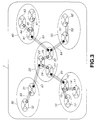
- FIG. 3 there is schematically illustrated an embodiment of network system according the present invention.
- the network system is generally indicated with a reference 1, of which the construction will be describe herebelow.
- the network system is formed from many computers and their peripheral devices or AV devices connected to each other.
- each of the devices incorporates an interface for connection thereof.
- Each of the devices will be referred to as "node” hereinunder.
- IEEE 1394 prescribes that one bus should include a maximum of 63 nodes.
- a small-scale network may be composed of a single bus. For connection of more nodes, however, a plurality of buses have to be provided and connected to each other with bridges. IEEE 1394 prescribes that one network system should include a maximum of 1,023 buses.
- the network system 1 comprises the bus for each of five subnetworks 10, 20, 30, 40 and 50 as shown in FIG. 3.
- the subnetwork 10 comprises three buses 11, 12 and 13 formed from a plurality ofnodes connected to each other with transmission control signal channels deigned in conformity with IEEE 1394, for example.
- the buses 11 and 12 are connected to each other with a first bridge 14, while the buses 12 and 13 are connected to each other with a first bridge 15.
- the subnetwork 20 includes three buses 21, 22 and 23.
- the buses 21 and 23 are connected to each other with a first bridge 24, while the buses 22 and 23 are connected to each other with a first bridge 25.
- the subnetwork 30 comprises two buses 31 and 32 are connected to each other with a first bridge 33.
- the subnetwork 40 comprises three buses 41, 42 and 43.
- the buses 41 and 42 are connected to each other with a first bridge 45, while the buses 41 and 43 are connected to each other with a first bridge 44.
- the subnetwork 50 comprises two buses 51 and 52 connected to each other with a first bridge 53.
- the subnetworks 10 and 20 are connected to each other with a second bridge 61
- the subnetworks 20 and 30 are connected to each other with a second bridge 62
- the subnetworks 20 and 40 are connected to each other with a second bridge 63
- the subnetworks 20 and 50 are connected to each other with a second bridge 64.
- Each of the subnetworks has a channel ID peculiar to the network system.
- Each of the buses in each subnetwork has a bus ID peculiar to the subnetwork.
- each of the nodes in each bus has a physical ID peculiar to the bus.
- each node can be definitely identified with the channel, bus and physical IDs in the network system.
- Each node incorporates an inner register which holds such channel, bus and physical IDs for the node.
- the first bridge is generally indicated with a reference 400.
- the first bridge 400 comprises portals 402 0 and 402 1 connected to each other with a fabric 401 being a fiber channel switch.
- the portals 402 0 and 402 1 are connected to each node with an IEEE 1394 bus, respectively. It should be noted that the portal is also a node.
- the first bridge will be further described later concerning its construction and function.
- the second bridge is generally indicated with a reference 410.
- the second bridge 410 comprises portals 412 0 , 412 1 and 412 N-1 connected to each other with a fabric 411 being a fiber channel switch.
- Each of the portals 412 0 , 412 1 and 412 N-1 is connected to each node with an IEEE 1394 bus, respectively.
- the second bridge will be further described later concerning its construction and function.
- the packet comprises a packet header and a data block.
- the packet header includes a source ID field indicative of a source node ID, and a destination ID field.
- Each of the source and destination IDs is of 16 bits.
- the 16-bit destination ID includes three fields of 5-bit subnetwork ID, 5-bit bus ID and 6-bit physical ID, respectively.
- the 16-bit source ID includes three fields for 5-bit subnetwork ID, 5-bit bus ID and 6-bit field ID, respectively, as shown in FIG. 7(B).
- FIGS, 8(A) and 8(B) show formats of the conventional destination ID and source IDs, respectively, for comparison with those of the destination and source IDs in the network system of the present invention.
- each of the conventional destination and source IDs includes only a 10-bit bud ID and 6-bit physical ID.
- a packet is to be transferred mainly in three modes as will be shown below.
- a first mode of them is a "bus broadcast to transmit a packet to all nodes in one bus”
- second one is a “global broadcast to transmit a packet to all nodes in a network system
- third is a "unicast to transmit a packet to a single node”.
- These destinations are identified with IDs of a packet as shown in Table 1.
- the packet destination is defined in further detail.
- bus and physical IDs in the destination ID field are 0 - 1e, 0 - le and 0 - 3e, respectively, in hexadecimal notation while all the subnetwork, bus and physical IDs in the source ID field are undefined ( ⁇ : don't care)
- a packet is unicast to a certain node in a certain bus.
- bus and physical IDs in the destination ID field are 0 - 1e, 0 - 1e and 3f, respectively, while all the subnetwork, bus and physical IDs in the source ID field are undefined ( ⁇ )
- a packet is broadcast to a certain bus.
- bus and physical IDs in the destination ID field are 1f, 1f and 0 - 3e, respectively, in hexadecimal notation while the subnetwork, bus and physical IDs in the source ID field are undefined ( ⁇ ), a packet is unicast to a certain node in a local bus.
- bus and physical IDs in the destination ID field are 1f, 1f and 3f, respectively, while the subnetwork, bus and physical IDs in the source ID field are 0 - 1e, 0 - 1e and undefined ( ⁇ ), respectively, a packet is globally broadcast to all buses.
- bus and physical IDs in the destination ID field are 1f, 1f and 3f, respectively, in hexadecimal notation while the subnetwork, bus and physical IDs in the source ID field are 1f, 1f and undefined ( ⁇ ), respectively, a packet is broadcast to a local bus.
- FIG. 9(A) shows a 32-bit bus routing register
- FIG. 9(B) shows a 16-bit subnetwork routing register
- FIG. 9(C) shows a 5-bit node IDs register.
- the IDs register includes a 5-bit subnetwork ID field, 5-bit bus ID field, and a 6-bit offset ID field holding a physical ID, as shown in FIG. 9(C).
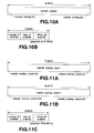
- the second bridge including two portals includes two registers: a 32-bit subnetwork routing register as shown in FIG. 10(A) and a 16-bit node IDs register as shown in FIG. 10(B).
- This node IDs register also includes a 5-bit subnetwork ID field, 5-bit bus ID field, and a 6-bit offset ID field holding a physical ID.
- the second bridge including three portals has three registers: a 32-bit subnetwork inport routing register as shown in FIG. 11(A), a 32-bit subnetwork output routing register as shown in FIG. 11(B) and a 16-bit node IDs register as shown in FIG. 11(C). Also, this node IDs register includes a 5-bit subnetwork ID field, 5-bit bus ID field, and a 6-bit offset ID field holding a physical ID.
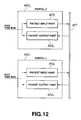
- the portals of the first bridge will be illustrated in detail in FIG. 12.
- the portals are generally indicated with references 402 0 and 402 1 , respectively.
- the portal 402 0 includes a packet input part 403 i and a packet output part 403 o
- the portal 402 1 includes a packet input part 404 i and a packet output part 404 o .
- the packet input and output parts connected to an inner fabric 401 as shown.
- the packet input part 403 i is constructed as shown in FIG. 13.
- a packet passed to an IEEE 1394 bus is received by a packet receiver 421, and stored into a packet buffer 422.
- Source and destination IDs from the packet buffer 422 are supplied to a comparison/calculation circuit 428 which is also supplied with ID values from the subnetwork routing register 425, bus routing register 426 and node IDs register 427 having been described with reference to FIG. 9.
- the comparison/calculation circuit 428 will judge, based on these signals, whether the packet is to be transferred, and when it decides that the packet is to be transferred, will activate an output signal, and open a gate 423 to transmit the packet to the inner fabric 401.
- the packet output part 403 o is constructed as shown in FIG. 14.
- the packet having been passed to the inner fabric 401 is acquired into a packet buffer 431, and transmitted from a packet transmitter 432 to the packet receiver 421 via the IEEE 1394 and an output terminal 433.
- the portals are generally indicated with references 412 0 , and 412 1 , and 412 N-1 , respectively.
- the portal 412 0 includes a packet input part 413 i and a packet output part 413 o
- the portal 412 1 includes a packet input part 414 i and a packet output part 414 o
- the portal 412 N-1 includes a packet input part 415 i and a packet output part 415 o .
- the packet input and output parts connected to an inner fabric 411 as shown.
- a packet passed to an IEEE 1394 bus is received by a packet receiver 441, and stored into a packet buffer 442.
- Source and destination IDs from the packet buffer 442 are supplied to a comparison/calculation circuit 447 which is also supplied with ID values from the subnetwork routing register 445 and node IDs register 446 having been described with reference to FIG. 10.
- the comparison/calculation circuit 447 will judge, based on these signals, whether the packet is to be transferred, and when it decides that the packet is to be transferred, will activate an output signal, and open a gate 443 to transmit the packet to the inner fabric 411.
- the packet output part 413 o is constructed as shown in FIG. 17.
- the packet having been passed to the inner fabric 411 is acquired into a packet buffer 435, and transmitted from a packet transmitter 452 to the packet receiver 441via the IEEE 1394 and an output terminal 453.
- the second bridge including three portals comprises, for the packet input part 413i, a subnetwork routing inport register 445 instead of the subnetwork routing inport register 445 shown in FIG. 16.
- the comparison/calculation circuit 447 will judge, based on these signals, whether the packet is to be transferred, and when it decides that the packet is to be transferred, will activate an output signal, and open a gate 443 to transmit the packet to the inner fabric 411.
- the packet output part 413 0 acquires, into the packet buffer 435, a packet passed to the inner fabric 411 as shown in FIG. 18.
- the packet buffer 435 will supply source and destination IDs to the comparison/calculation circuit 455 which is also supplied with an output from the subnetwork routing outport register 454 having been described with reference to FIG. 11.
- the comparison/calculation circuit 455 will judge, based on these signals, whether the packet is to be transferred, and when it decides that the packet is to be transferred, will activate an output signal, and open a gate 456 to transmit the packet from the IEEE 1394 and an output terminal 453 to the inner fabric 411.
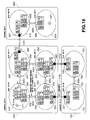
- FIG. 19 shows a network system comprising a second bridge including two portals.
- FIG. 20 shows another network system comprising a second bridge including three portals.
- the network system shown in FIG. 19 comprises three subnetworks 500, 600 and 700 connected to each other and having subnetwork ID # 0, #1 and #2, respectively.
- the subnetwork 500 incorporates four buses 510, 520, 530 and 540 of ID #0, #1, #2 and #3, respectively.
- the buses 510 and 520 are connected to each other with a first bridge 400 1
- buses 510 and 530 are connected to each other with a first bridge 400 2
- buses 520 and 540 are connected to each other with a first bridge 400 3
- buses 530 and 540 are connected to each other with a first bridge 400 4 .
- the subnetwork 600 incorporates two buses 610 and 620 of ID #0 and #1, respectively.
- the buses 610 and 620 are connected to each other with a first bridge 400 5 .
- the subnetwork 700 incorporates two buses 710 and 720 of ID #0 and #1, respectively, connected to each other with a first bridge 400 6 .
- the subnetworks 500 and 600 are connected to each other with a second portal 410 1
- the subnetworks 500 and 700 are connected to each other with second portals 410 2 and 410 3 .
- the first bridge 400 1 in the subnetwork 500 comprises a portal 550 in the bus 510, portal 551 in the bus 520 and a fabric (not shown).
- the first bridge 400 2 comprises a portal 552 in the bus 510, portal 553 in the bus 530, and a fabric.
- the first bridge 400 3 comprises a portal 552 in the bus 520, portal 553 in the bus 530, and a fabric.
- the first bridge 400 5 in the subnetwork 600 comprises a portal 655 in the bus 610, portal 656 in the bus 620 and a fabric.
- the first bridge 400 6 in the subnetwork 700 comprises a portal 755 in the bus 710, portal 756 in the bus 720, and a fabric.
- the second bridge 410 1 connecting the subnetworks 500 and 600 comprises a portal 558 in the bus 520 of the subnetwork 500, portal 657 in the bus 610 of the subnetwork 600, and a fabric.
- the second bridge 410 2 connecting the subnetworks 500 and 700 comprises portals 559 in the bus 530 of the subnetwork 500, portal 757 in the bus 710 of the subnetwork 700, and a fabric.
- the second bridge 410 3 comprises a portal 560 in the bus 540 of the subnetwork 500, portal 758 in the bus 720 of the subnetwork 700, and a fabric.
- This network system shown in FIG. 19 will be functionally described concerning a packet transmission from the node (X) 511 forming the bus 510 in the subnetwork 500 to a node 621 (Y) forming a bus 620 in the subnetwork 600, by way of example.
- This packet transmission is included in the unicast to a certain node in a certain bus in Table 1.
- the subnetwork, bus and physical IDs in the destination ID field of the logical format of the packet is 1, 1 and y, respectively.
- the packet input part of the portal 550 in the first bridge 400 1 is similar to the packet input part 403 1 shown in FIG. 13.
- a packet having of a subnetwork ID #1, bus ID #1 and physical ID #y in its destination ID field is received by the packet receiver 421 and stored in the packet buffer 422.
- a packet delivered from the packet buffer 422 and having a subnetwork ID #1 and bus ID #1 in its destination ID field is supplied to the comparison/calculation circuit 428 which is also supplied with ID values from the subnetwork routing register 425 and bus routing register 426 of the packet input part 403 i of the portal 550 carry flags as shown in FIG. 19. Namely, when each of these registers has 32 flag storage locations having address ID #0, #1, #2, #3, ...
- a flag "1" is set as each of the address IDs so as to correspond to bus and subnetwork IDs in the destination ID field of a destination to which a packet transfer is allowed.
- a flag is set in a location "0101...1" as indicated with BR.
- a flag is set in a location "0110...1” as indicated with SR.
- the register BR in the packet input part thereof has a content "0010...0" while the register SR has a content "0000...0".
- the comparison/calculation circuit 428 will decide that the packet is not to be transferred and not open the gate 423.
- the second bridge 400 2 will not pass the packet.
- the portal 551 forming along with the portal 550 the first bridge 400 1 will allow the packet transmitted from the portal 550 via the inner fabric into the packet output part similar in construction to the packet output part 403 o sown in FIG. 14.
- the packet will be acquired into the packet buffer 431 and transmitted from the packet transmitter 432 to the packet receivers of the packet input parts in other portion and the portals 554 and 558 in the bus 520 via the IEEE 1394 bus.
- the register BR in the packet input part thereof has a content "0110...1" while the register SR has a content "0010...1".
- the comparison/calculation circuit will decide that the packet is not to be transferred and not open the gate.
- the second bridge 400 3 will not pass the packet.
- the packet input part of the portal 558 in the second bridge 410 1 is similar in construction to the packet input part 413 i shown in FIG. 16.
- a packet having a subnetwork ID #1, bus ID #1 and physical ID #y in the destination ID field thereof is received by the packet receiver 441 and stored into the packet buffer 442.
- a subnetwork ID from the packet buffer 442, being "1” is supplied to the comparison/calculation circuit 447 which is also supplied with an ID value from the subnetwork routing inport register 445.
- the register 445 of the packet input part 413 i in the portal 558 carries flags as shown in FIG. 19. Namely, the register SR has a content "0100...1". Therefore, the comparison/calculation circuit 447 will decide that the packet is to be transferred, opens the gate 443 to transmit the packet stored in the packet buffer 442 to the inner fabric 411.
- the portal 657 forming along with the portal 558 the second bridge 410 1 passes the packet received via the inner fabric 411 to a packet output part similar in construction to the packet output part 413 o shown in FIG. 17. Then the packet is acquired into the packet buffer 451 and transmitted from the packet transmitter 452 to the portal 655 via the IEEE 1394 bus.
- the portal 655 forms the first bridge 400 5 connecting the buses 610 and 620, and comprises a packet input part similar in construction to the packet shown in FIG. 13. It includes a register BR having a content "0100...1” and a register SR having a content "0000...1". Therefore, the comparison/calculation circuit will decide that the packet is to be transferred, and open the gate 423 to transmit the packet to the inner fabric 401.
- the portal 656 forming along with the portal 655 the first bridge 400 5 will allow the packet transmitted from the portal 655 via the inner fabric into the packet output part similar in construction to the packet output part 403 o sown in FIG. 14.
- the packet will be acquired into the packet buffer and transmitted from the packet transmitter via the IEEE 1394 bus to a node 621 having a physical ID #y.
- the network system shown in FIG. 20 is formed from four subnetworks 500, 600, 700 and 800 having IDs 0, 1, 2 and 4, respectively, connected to each other.
- the subnetwork 500 is constructed generally similarly to the subnetwork 500 shown in FIG. 19 except for a portal 561 forming along with two other portals 658 and 855 a second bridge 410 4 in the bus 520.
- the subnetwork 600 incorporates a bus 610 having an ID #0.
- the bus 610 includes the portal 658.
- the subnetwork 800 incorporates a bus 810 having an ID #0 and including the portal 855.
- the subnetwork 700 is constructed similarly to the subnetwork 700 in FIG. 19.
- This network system shown in FIG. 20 will be functionally described concerning a packet transmission from the node (X) 511 forming the bus 510 in the subnetwork 500 to a node 811 (Y) forming a bus 820 in the subnetwork 800, by way of example.
- This packet transmission is included in the unicast to a certain node in a certain bus in Table 1.
- the subnetwork, bus and physical IDs in the destination ID field of the logical format of the packet is 3, 0 and y, respectively.
- the network system in FIG. 19 has a large difference from that in FIG. 20 in that the second bridge 410 4 connecting the three subnetworks 500, 600 and 800 is formed from three portals 561, 658 and 855.
- the portal 550 in the first bridge 400 1 has a packet input part similar in construction to the packet input part 403 i shown in FIG. 13.
- a packet having a subnetwork ID #3, bus ID #0 and physical ID #y in the destination ID field thereof is received by the packet receiver 421 and stored into the packet buffer 422.
- a packet from the packet buffer 422 having a subnetwork ID #3 and bus ID #0 in the destination ID field thereof is supplied to the comparison/calculation circuit 428 which is also supplied with ID values from the subnetwork routing register 425 and bus routing register 426.
- the two registers 425 and 426 of the packet input part 403 i in the portal 550 carry flags as shown in FIG. 19.
- the register BR has a flag contains "0101...1" while the register SR has a flag content "0111...1". Therefore, the comparison/calculation circuit 428 decides that the packet is to be transferred, opens the gate 423 to transmit the packet stored in the packet buffer 422 to the inner fabric 401. Since the operations of the portals 551, 552 and 554 are same as mentioned above, they will not be described any longer.
- the portal 561 in the bus 520 has a packet input part similar in construction to that shown in FIG. 16 except that the subnet routing register 445 is a subnet routing inport register 445.
- the register SRI has a flag content "0101...1" as shown in FIG. 20. Therefore, the comparison/calculation circuit 447 will open the gate 443 to transmit the packet to the inner fabric 411.
- the packet output parts of the portals 658 and 855 are similar in construction to the packet output part shown in FIG. 18, and acquire the packet from the inner fabric 411 into the packet buffer 451.
- a packet from this packet buffer 451 having a subnetwork ID in the destination ID field thereof is supplied to the comparison/calculation circuit 455 which is also supplied with a signal from the subnetwork routing outport register 454.
- the register SR in the portal 658 has a flag content "0100...1"
- the register SR in the portal 855 has a flag content "0001...1".
- the comparison/calculation circuit 455 of the packet output part in the portal 658 will not open the gate 456.
- the comparison/calculation circuit of the packet output part in the portal 855 decides that the packet is to be transmitted and opens the gate to transmit a packet from the packet transmitter 452 to a node (Y) 811 of a physical ID #Y via the IEEE 1394.
- step S1 it is judged at step S1 whether the subnetwork and bus IDs in the destination ID field of a received packet is "0 ⁇ 1f". When it is decided that the IDs are not "0 ⁇ 1f", the operation goes to step S2. At this step S2, it is judged whether the subnetwork ID in the destination ID field and that in the node IDs field of the packet are equal to each other. If it is decided that they are not equal to each other, the operation goes to step S3. It is judged at this step S3 whether the bus ID in the destination ID field and that in the node IDs field of the packet are equal to each other. When it is decided that they are equal to each other, the operation goes to step S4 and the packet is not transferred.
- step S3 if it is decided at step S3 that the bus ID in the destination ID field and that in the node IDs field are not equal to each other, the operation goes to step S5.
- step S5 the content of the bus routing register is read and it is judged whether the content is equal to the bus ID.
- step S7 the operation goes to step S7 to deliver the packet to the inner fabric from which the packet is transmitted from the portal on the opposite side. If it is decided that they are not equal, the operation goes to step S4 and the packet is not transmitted.
- Step S2 If it is decided at Step S2 that the subnetwork ID in the destination ID field is not equal to that in the node IDs field, the operation goes to step S6 where the subnet routing register content is read to judge whether the ID value is equal to the subnetwork ID. When it is decided that they are equal to each other, the operation goes to step S7 where the packet is delivered to the inner fabric from which the packet is transmitted from the portal on the opposite side. If they are not equal, the operation goes to step S4 and the packet is not transferred.
- step S8 If it is decided at step S1 that the subnetwork and bus IDs in the destination ID field are "0 ⁇ 1f", the operation goes to step S8 where it is judged whether the subnetwork and bus IDs in the destination ID field are "0 ⁇ 1f". When it is decided that they are not "0 ⁇ 1f", the operation goes to step S9 where it is judged whether the physical ID in the destination ID field is "0 ⁇ 3f". When it is decided that the physical ID is "0 ⁇ 3f”, the operation goes to step S10 where the bus routing register content "0 ⁇ 1f" is 1. If it is decided that the register content is 1, the operation goes to step S7. The packet is delivered to the inner fabric from which it is transmitted from the portal on the opposite side.
- step S8 When it is decided at step S8 that the subnetwork and bus IDs are "0 ⁇ 1f" or when it is decided at step S9 that the physical ID is not "0 ⁇ 3f" , the operation goes to step S4 and the packet is not transferred.
- step S10 When it is judged at step S10 that the bus routing register content "0 ⁇ 1f" is not 1, the operation goes to step S11 where it is judged whether the subnetwork routing register content "0 ⁇ 1f" is 1. If the register content is 1, the operation goes to step S7 and the packet is delivered to the inner fabric from which the packet is transmitted from the portal on the opposite side. When it is decided that the register content is not 1, the operation goes to step S4 and the packet is not transferred.
- step S21 it is judged at step S21 whether the subnetwork and bus IDs in the destination ID field of a received packet is "0 ⁇ 1f". When it is decided that the IDs are not "0 ⁇ 1f", the operation goes to step S22. At this step S22, it is judged whether the subnetwork routing inport register content and the subnetwork ID in the destination ID field of the packet are equal to each other. If it is decided that they are not equal to each other, the operation goes to step S23 and the packet is not transferred. When it is decided that they are equal to each other, the operation goes to step S24 and the packet is delivered to the inner fabric.
- step S21 if it is decided at step S21 that the subnetwork and bus IDs are "0 ⁇ 1f”, the operation goes to step S25.
- step S25 it is judged whether the subnetwork and bus IDs in the destination ID field are "0 ⁇ 1f". If it is decided that they are not "0 ⁇ 1f", the operation goes to step S26 where it is judged whether the physical ID in the destination ID field of the packet is "0 ⁇ 3f". If it is decided that the physical ID is "0 ⁇ 3f" , the operation goes to step S27 where it is judged whether te subnetwork routing inport register content "0 ⁇ 1f" is 1. When it is judged that it is 1, the operation goes to step S24 and the packet is transferred to the inner fabric.
- step S25 if it is decided at step S25 that the subnetwork and bus IDs are "0 ⁇ 1f”, if it is decided at step S26 that the physical ID is not "0 ⁇ 3f" or if it is decided at step S27 that the subnetwork routing inport register content is not 1, the operation goes to S23 and the packet is not transferred .
- step S31 it is judged whether the subnetwork and bus IDs in the destination ID field of a received packet are "0 ⁇ 1f". If it is decided that they are not "0 ⁇ 1f", the operation goes to step S32 where it is judged whether the subnetwork routing outport register content and the subnetwork ID in the destination ID field of the packet are equal to each other. If it is decided that they are not equal, the operation goes to step S33 and nothing is done.
- step S31 if it is decided at step S31 that the subnetwork and bus IDs are "0 ⁇ 1f”, the operation goes to step S34 where it is judged whether the subnetwork routing outport register content "0 ⁇ 1f" is 1. When it is decided that the subnetwork routing outport register content "0 ⁇ 1f" is not 1, the operation goes to step S33 and nothing is done.
- step S32 If it is decided at step S32 that the subnetwork routing output register content is equal to the subnetwork ID in the destination ID field of the packet, the operation goes to S35 and the packet is transmitted from the portal to the bus. Also when it is decided at step S34 that the register content "0 ⁇ 1f" is 1, the operation goes to step S35 and the packet is transmitted from the portal to the bus.
- a network formed from nodes conforming to IEEE 1394 is a hierarchy formed from buses and subnetworks such that it can be judged for each ID whether a packet is to be routed over a bridge. Therefore, bus and subnetwork IDs can be freely assigned as compared with the conventional network system in which packet routing is done through comparison in magnitude between IDs. Thus, less ID reassignment is required even when the bus topology has changed.
Landscapes
- Engineering & Computer Science (AREA)
- Computer Networks & Wireless Communication (AREA)
- Signal Processing (AREA)
- Small-Scale Networks (AREA)
- Data Exchanges In Wide-Area Networks (AREA)
- Computer And Data Communications (AREA)
Applications Claiming Priority (2)
| Application Number | Priority Date | Filing Date | Title |
|---|---|---|---|
| JP05561498 | 1998-03-06 | ||
| JP10055614A JPH11261564A (ja) | 1998-03-06 | 1998-03-06 | ネットワークシステム |
Publications (3)
| Publication Number | Publication Date |
|---|---|
| EP0948167A2 true EP0948167A2 (de) | 1999-10-06 |
| EP0948167A3 EP0948167A3 (de) | 2006-03-08 |
| EP0948167B1 EP0948167B1 (de) | 2009-08-26 |
Family
ID=13003661
Family Applications (1)
| Application Number | Title | Priority Date | Filing Date |
|---|---|---|---|
| EP99301659A Expired - Lifetime EP0948167B1 (de) | 1998-03-06 | 1999-03-05 | Netzwerkssystem |
Country Status (7)
| Country | Link |
|---|---|
| US (1) | US6724763B1 (de) |
| EP (1) | EP0948167B1 (de) |
| JP (1) | JPH11261564A (de) |
| KR (1) | KR100607710B1 (de) |
| AU (1) | AU765091B2 (de) |
| DE (1) | DE69941318D1 (de) |
| TW (1) | TW428406B (de) |
Cited By (2)
| Publication number | Priority date | Publication date | Assignee | Title |
|---|---|---|---|---|
| FR2802740A1 (fr) * | 1999-12-15 | 2001-06-22 | Canon Kk | Procede et dispositif de communication entre deux noeuds d'interconnexion connectes a deux bus de communication |
| EP1615389A1 (de) * | 2004-07-09 | 2006-01-11 | Sony Corporation | Überbrückung der IEEE-1394 Netzwerke |
Families Citing this family (4)
| Publication number | Priority date | Publication date | Assignee | Title |
|---|---|---|---|---|
| JP2002111704A (ja) * | 2000-09-29 | 2002-04-12 | Sony Corp | データ送受信装置及び方法 |
| DE10145596A1 (de) | 2001-09-15 | 2003-04-03 | Philips Corp Intellectual Pty | Netzwerk mit mehreren Sub-Netzwerken |
| JP2006311288A (ja) * | 2005-04-28 | 2006-11-09 | Sony Corp | オーディオ中継装置及びオーディオ中継方法 |
| KR100832545B1 (ko) * | 2006-12-08 | 2008-05-27 | 한국전자통신연구원 | Ieee 1394 브릿지 구현 방법 및 그 장치 |
Citations (1)
| Publication number | Priority date | Publication date | Assignee | Title |
|---|---|---|---|---|
| US5615207A (en) | 1995-06-07 | 1997-03-25 | Advanced Micro Devices, Inc. | Side bus to dynamically off load main bus |
Family Cites Families (12)
| Publication number | Priority date | Publication date | Assignee | Title |
|---|---|---|---|---|
| JPH0618374B2 (ja) * | 1985-03-18 | 1994-03-09 | 株式会社日立製作所 | マルチネツトワ−クシステムのデ−タ伝送方法 |
| US5018137A (en) * | 1988-06-27 | 1991-05-21 | Digital Equipment Corporation | Transparent load sharing for parallel networks |
| WO1991008627A1 (en) * | 1989-12-04 | 1991-06-13 | Codex Corporation | Packet filter for bridge between networks |
| US5088090A (en) * | 1990-01-31 | 1992-02-11 | Rad Network Devices Ltd. | Routing system to interconnect local area networks |
| US5214646A (en) * | 1990-01-31 | 1993-05-25 | Amnon Yacoby | System and method for interconnecting local area networks |
| JPH05114905A (ja) * | 1991-04-08 | 1993-05-07 | Digital Equip Corp <Dec> | 単一アドレス及びプロトコール・テーブル・ブリツジを使用したメツセージの処置フイルタリング |
| US5504747A (en) * | 1993-03-03 | 1996-04-02 | Apple Computer, Inc. | Economical payload stream routing in a multiple-ring network |
| EP0675616A3 (de) * | 1994-03-04 | 1995-11-29 | At & T Corp | Lokales Netz. |
| JP3454294B2 (ja) * | 1994-06-20 | 2003-10-06 | インターナショナル・ビジネス・マシーンズ・コーポレーション | マルチプル・バス情報処理システム及びブリッジ回路 |
| JP4019482B2 (ja) * | 1998-01-23 | 2007-12-12 | ソニー株式会社 | 通信システム及びブリッジ装置 |
| JPH11215186A (ja) * | 1998-01-23 | 1999-08-06 | Sony Corp | ネットワークシステム |
| JP2000349805A (ja) * | 1999-06-07 | 2000-12-15 | Sony Corp | バスネットワーク管理方法およびそれを利用するバスネットワーク、並びに情報提供媒体 |
-
1998
- 1998-03-06 JP JP10055614A patent/JPH11261564A/ja not_active Withdrawn
-
1999
- 1999-03-01 TW TW088103089A patent/TW428406B/zh not_active IP Right Cessation
- 1999-03-01 US US09/259,685 patent/US6724763B1/en not_active Expired - Fee Related
- 1999-03-01 AU AU18493/99A patent/AU765091B2/en not_active Ceased
- 1999-03-05 EP EP99301659A patent/EP0948167B1/de not_active Expired - Lifetime
- 1999-03-05 DE DE69941318T patent/DE69941318D1/de not_active Expired - Fee Related
- 1999-03-05 KR KR1019990007251A patent/KR100607710B1/ko not_active Expired - Fee Related
Patent Citations (1)
| Publication number | Priority date | Publication date | Assignee | Title |
|---|---|---|---|---|
| US5615207A (en) | 1995-06-07 | 1997-03-25 | Advanced Micro Devices, Inc. | Side bus to dynamically off load main bus |
Cited By (2)
| Publication number | Priority date | Publication date | Assignee | Title |
|---|---|---|---|---|
| FR2802740A1 (fr) * | 1999-12-15 | 2001-06-22 | Canon Kk | Procede et dispositif de communication entre deux noeuds d'interconnexion connectes a deux bus de communication |
| EP1615389A1 (de) * | 2004-07-09 | 2006-01-11 | Sony Corporation | Überbrückung der IEEE-1394 Netzwerke |
Also Published As
| Publication number | Publication date |
|---|---|
| TW428406B (en) | 2001-04-01 |
| DE69941318D1 (de) | 2009-10-08 |
| EP0948167B1 (de) | 2009-08-26 |
| JPH11261564A (ja) | 1999-09-24 |
| AU765091B2 (en) | 2003-09-11 |
| KR100607710B1 (ko) | 2006-07-31 |
| US6724763B1 (en) | 2004-04-20 |
| KR19990077619A (ko) | 1999-10-25 |
| EP0948167A3 (de) | 2006-03-08 |
| AU1849399A (en) | 1999-09-16 |
Similar Documents
| Publication | Publication Date | Title |
|---|---|---|
| JP3737517B2 (ja) | マルチキャスト・パケットのlan上における、透過形の中間システムを基礎とするフィルタリングの方法および装置 | |
| EP1449326B1 (de) | System und vorrichtung zum tunneln des dienstes von explizit-multicast | |
| US5933605A (en) | Apparatus for filtering multicast messages transmitted between subnetworks based upon the message content | |
| US6539022B1 (en) | Network device with multicast forwarding data | |
| US8031640B2 (en) | Packet transmission apparatus, packet forwarding method and packet transmission system | |
| US5802047A (en) | Inter-LAN connecting device with combination of routing and switching functions | |
| US5910955A (en) | Switching hub capable of controlling communication quality in LAN | |
| US5469432A (en) | High-speed digital communications network | |
| US5539737A (en) | Programmable disrupt of multicast packets for secure networks | |
| JP4587446B2 (ja) | ネットワークシステム、並びにスイッチ装置及び経路管理サーバ及びそれらの制御方法、及び、コンピュータプログラム及びコンピュータ可読記憶媒体 | |
| US20030112810A1 (en) | Method for forwarding packets by connecting network segments through a wireless channel and wireless bridging apparatus using the same | |
| US20110158086A1 (en) | Packet ring network system, packet forwarding method and node | |
| CN112532563B (zh) | 报文的发送方法和装置 | |
| JP2003526277A (ja) | デュアル・モードによる仮想ネットワーク・アドレス指定方式 | |
| JPH0799837B2 (ja) | メッセージパッケージ伝送方法及び装置 | |
| US6272135B1 (en) | Data communication method and system for one-to-one communication and one-to-plurality broadcast communication | |
| US7778255B2 (en) | Frame transfer method and frame transfer device | |
| JPH0824304B2 (ja) | 通信ネットワークから不要なデータパケットを破棄する方法 | |
| US6563834B1 (en) | Network path controlling method and apparatus | |
| US6724763B1 (en) | Network system | |
| US6335939B1 (en) | Apparatus and method for selectively supplying data packets between media domains in a network repeater | |
| US6721319B1 (en) | Network system | |
| EP0932278A1 (de) | Netzwerksystem | |
| US6131124A (en) | Data communication method and data communication system using this method | |
| JP2006511115A (ja) | パケット交換方式ネットワークにおけるリターンパス導出 |
Legal Events
| Date | Code | Title | Description |
|---|---|---|---|
| PUAI | Public reference made under article 153(3) epc to a published international application that has entered the european phase |
Free format text: ORIGINAL CODE: 0009012 |
|
| AK | Designated contracting states |
Kind code of ref document: A2 Designated state(s): AT BE CH CY DE DK ES FI FR GB GR IE IT LI LU MC NL PT SE |
|
| AX | Request for extension of the european patent |
Free format text: AL;LT;LV;MK;RO;SI |
|
| PUAL | Search report despatched |
Free format text: ORIGINAL CODE: 0009013 |
|
| AK | Designated contracting states |
Kind code of ref document: A3 Designated state(s): AT BE CH CY DE DK ES FI FR GB GR IE IT LI LU MC NL PT SE |
|
| AX | Request for extension of the european patent |
Extension state: AL LT LV MK RO SI |
|
| RIC1 | Information provided on ipc code assigned before grant |
Ipc: H04L 12/56 20060101ALI20060117BHEP Ipc: H04L 12/28 20060101ALI20060117BHEP Ipc: H04L 12/46 20060101AFI20060117BHEP |
|
| 17P | Request for examination filed |
Effective date: 20060825 |
|
| AKX | Designation fees paid |
Designated state(s): DE FI FR GB IT NL SE |
|
| 17Q | First examination report despatched |
Effective date: 20071008 |
|
| GRAP | Despatch of communication of intention to grant a patent |
Free format text: ORIGINAL CODE: EPIDOSNIGR1 |
|
| GRAS | Grant fee paid |
Free format text: ORIGINAL CODE: EPIDOSNIGR3 |
|
| GRAA | (expected) grant |
Free format text: ORIGINAL CODE: 0009210 |
|
| AK | Designated contracting states |
Kind code of ref document: B1 Designated state(s): DE FI FR GB IT NL SE |
|
| REG | Reference to a national code |
Ref country code: GB Ref legal event code: FG4D |
|
| REF | Corresponds to: |
Ref document number: 69941318 Country of ref document: DE Date of ref document: 20091008 Kind code of ref document: P |
|
| PG25 | Lapsed in a contracting state [announced via postgrant information from national office to epo] |
Ref country code: SE Free format text: LAPSE BECAUSE OF FAILURE TO SUBMIT A TRANSLATION OF THE DESCRIPTION OR TO PAY THE FEE WITHIN THE PRESCRIBED TIME-LIMIT Effective date: 20090826 Ref country code: FI Free format text: LAPSE BECAUSE OF FAILURE TO SUBMIT A TRANSLATION OF THE DESCRIPTION OR TO PAY THE FEE WITHIN THE PRESCRIBED TIME-LIMIT Effective date: 20090826 |
|
| NLV1 | Nl: lapsed or annulled due to failure to fulfill the requirements of art. 29p and 29m of the patents act | ||
| PG25 | Lapsed in a contracting state [announced via postgrant information from national office to epo] |
Ref country code: NL Free format text: LAPSE BECAUSE OF FAILURE TO SUBMIT A TRANSLATION OF THE DESCRIPTION OR TO PAY THE FEE WITHIN THE PRESCRIBED TIME-LIMIT Effective date: 20090826 |
|
| PLBE | No opposition filed within time limit |
Free format text: ORIGINAL CODE: 0009261 |
|
| STAA | Information on the status of an ep patent application or granted ep patent |
Free format text: STATUS: NO OPPOSITION FILED WITHIN TIME LIMIT |
|
| 26N | No opposition filed |
Effective date: 20100527 |
|
| GBPC | Gb: european patent ceased through non-payment of renewal fee |
Effective date: 20100305 |
|
| REG | Reference to a national code |
Ref country code: FR Ref legal event code: ST Effective date: 20101130 |
|
| PG25 | Lapsed in a contracting state [announced via postgrant information from national office to epo] |
Ref country code: FR Free format text: LAPSE BECAUSE OF NON-PAYMENT OF DUE FEES Effective date: 20100331 |
|
| PG25 | Lapsed in a contracting state [announced via postgrant information from national office to epo] |
Ref country code: DE Free format text: LAPSE BECAUSE OF NON-PAYMENT OF DUE FEES Effective date: 20101001 |
|
| PG25 | Lapsed in a contracting state [announced via postgrant information from national office to epo] |
Ref country code: GB Free format text: LAPSE BECAUSE OF NON-PAYMENT OF DUE FEES Effective date: 20100305 Ref country code: IT Free format text: LAPSE BECAUSE OF FAILURE TO SUBMIT A TRANSLATION OF THE DESCRIPTION OR TO PAY THE FEE WITHIN THE PRESCRIBED TIME-LIMIT Effective date: 20090826 |