EP0948172A2 - Verfahren zur automatischen taktfreien Erkennung von Signal-Modulationsarten - Google Patents
Verfahren zur automatischen taktfreien Erkennung von Signal-Modulationsarten Download PDFInfo
- Publication number
- EP0948172A2 EP0948172A2 EP99106431A EP99106431A EP0948172A2 EP 0948172 A2 EP0948172 A2 EP 0948172A2 EP 99106431 A EP99106431 A EP 99106431A EP 99106431 A EP99106431 A EP 99106431A EP 0948172 A2 EP0948172 A2 EP 0948172A2
- Authority
- EP
- European Patent Office
- Prior art keywords
- values
- signal
- phase
- frequency
- functions
- Prior art date
- Legal status (The legal status is an assumption and is not a legal conclusion. Google has not performed a legal analysis and makes no representation as to the accuracy of the status listed.)
- Granted
Links
- 238000000034 method Methods 0.000 title claims abstract description 43
- 230000006870 function Effects 0.000 claims abstract description 61
- 238000001514 detection method Methods 0.000 claims abstract description 18
- 230000009466 transformation Effects 0.000 claims abstract description 10
- 238000011156 evaluation Methods 0.000 claims abstract description 5
- 230000003595 spectral effect Effects 0.000 claims description 20
- 238000012545 processing Methods 0.000 claims description 17
- 230000015572 biosynthetic process Effects 0.000 claims description 10
- 230000008569 process Effects 0.000 claims description 7
- 238000009795 derivation Methods 0.000 claims description 6
- 238000004458 analytical method Methods 0.000 claims description 3
- 238000013528 artificial neural network Methods 0.000 claims description 3
- 238000009825 accumulation Methods 0.000 claims description 2
- 238000010606 normalization Methods 0.000 claims description 2
- 238000001228 spectrum Methods 0.000 claims 3
- 230000002452 interceptive effect Effects 0.000 claims 1
- 238000000605 extraction Methods 0.000 abstract description 14
- 230000003044 adaptive effect Effects 0.000 abstract description 4
- 238000004891 communication Methods 0.000 abstract description 3
- 230000009467 reduction Effects 0.000 abstract description 2
- 230000002123 temporal effect Effects 0.000 description 4
- 230000002596 correlated effect Effects 0.000 description 3
- 230000000875 corresponding effect Effects 0.000 description 3
- 230000004069 differentiation Effects 0.000 description 2
- 238000009826 distribution Methods 0.000 description 2
- 238000002474 experimental method Methods 0.000 description 2
- 238000012544 monitoring process Methods 0.000 description 2
- 230000000717 retained effect Effects 0.000 description 2
- 238000005070 sampling Methods 0.000 description 2
- 238000012360 testing method Methods 0.000 description 2
- 238000012935 Averaging Methods 0.000 description 1
- 230000000712 assembly Effects 0.000 description 1
- 238000000429 assembly Methods 0.000 description 1
- 230000009286 beneficial effect Effects 0.000 description 1
- 238000012512 characterization method Methods 0.000 description 1
- 230000001934 delay Effects 0.000 description 1
- 230000003111 delayed effect Effects 0.000 description 1
- 238000011161 development Methods 0.000 description 1
- 230000018109 developmental process Effects 0.000 description 1
- 238000001914 filtration Methods 0.000 description 1
- 238000003909 pattern recognition Methods 0.000 description 1
- 238000011084 recovery Methods 0.000 description 1
- 238000000926 separation method Methods 0.000 description 1
- 238000007493 shaping process Methods 0.000 description 1
- 230000001629 suppression Effects 0.000 description 1
- 230000001360 synchronised effect Effects 0.000 description 1
- 238000000844 transformation Methods 0.000 description 1
Images


Classifications
-
- H—ELECTRICITY
- H04—ELECTRIC COMMUNICATION TECHNIQUE
- H04L—TRANSMISSION OF DIGITAL INFORMATION, e.g. TELEGRAPHIC COMMUNICATION
- H04L27/00—Modulated-carrier systems
- H04L27/0012—Modulated-carrier systems arrangements for identifying the type of modulation
Definitions
- the invention relates to a method for the automatic detection of signal modulation types according to the preamble of claim 1.
- the modulation types are between continuous (analog) and discrete distinguish between (digitally) modulated types.
- the primary types of modulation are predominantly digital today.
- Step clock signal can be recovered and used for further signal analysis. This is achieved in particular by extracting the step clock instants that are synchronous with the signal
- Finding the distributions of the amplitude, instantaneous frequency and phase values typical for the modulation types is made easier. This means beneficial suppression the irrelevant values and thus an increase in performance and a significant reduction in data for the subsequent signal processing.
- An example of such a, clock-based The procedure is described in [1]. Such procedures use the close connection of signal bandwidth and walking speed.
- Analog modulated signals and certain test signals such as e.g. B. linear frequency modulated Signals for testing short-wave radio channels.
- B linear frequency modulated Signals for testing short-wave radio channels.
- Modulation types in which the actually discrete ones are formed by appropriate pulse shaping Value ranges are again made largely continuous.
- modulation also the in-phase and quadrature components against each other offset, so that special additional clock derivations would be required for this. This applies, for example, to CPM signals (CPM: Continuous Phase Modulation) [2].
- CPM signals CPM: Continuous Phase Modulation
- GMSK Gaussian Minimum-Shift Keying
- the invention has for its object radio signals regardless of their type of modulation and without the use of possibly assigned step cycle times, d. H. tact-free, with a generally applicable procedure and automatically recognize and according to your To be able to classify the type of modulation.
- the uniformity of the procedure is essential for all radio signals to be recognized.
- the process is also said to be particularly robust be and the reference functions used for recognition in the context of a learning phase [4] Generate quickly and adaptively from new signal situations. Robust is in that Meaning meant that the method is still largely with increasing signal interference delivers true results. To ensure the performance of cycle-based processes to achieve, it is indicated that the relevant signal parameter values also without Find the knowledge of the exact step timing and the further processing on it To support values.
- the task is based on a method according to Preamble of claim 1, by the specified in the characterizing part of claim 1 Features resolved.
- Advantageous refinements and developments of the subject the invention are specified in subclaims 2 to 6.
- the incoming radio signal is first mixed in a known manner and digitized using an analog-digital converter.
- the frequency band portion of interest for the detection of modulation types can, for example, be measured automatically by the arrangement described in [5], a spectral segmenter, according to the parameters center frequency and bandwidth.
- the signal to be analyzed is then obtained by mixing it into the baseband and filtering it out.
- the cut-off frequency of the low-pass filter used depends on the previously measured signal bandwidth.
- the components of the complex baseband signal are thus available for further processing.
- the complex signal goes through non-linear operations in parallel branches, a square and an absolute square, followed by a DFT (DFT: digital Fourier transformation) [6] to determine whether and if so, which one Frequency a step clock spectral component can be detected.
- a detection takes place when a predetermined detection threshold is exceeded. So deliver CPM signals behind the square of the complex signal form a spectral line deliver at half the step frequency and simple digitally modulated signals behind the square of magnitude, a trained spectral line at the full step frequency.
- the reciprocal of the frequency of the detected step clock spectral component becomes the time interval for the subsequent differential phase formation is determined and stored.
- step clock spectral line and its Frequency values are also used for the modulation type decision to be made later cached. If there is no clear step clock spectral component, then the time interval required for the later formation of the difference phase from the reciprocal of the known signal bandwidth determined. In contrast, the step clock spectral component is not for the generation of the step clock time points for the selection of relevant signal parameter values needed because the method according to the invention is a clock-free method for modulation type detection. This is in terms of effort the robust way of working and the versatility advantageous compared clock-based procedure. The extraction of the relevant signal parameter values is carried out here according to a special method, explained in more detail below.
- the complex baseband signal is transformed from Cartesian to polar coordinates, ie for the value sequences of the real and imaginary part, value sequences for the amplitude a and the phase ⁇ are determined. From the temporal course of the value sequences thus determined for the amplitude, a i , and for the phase, ⁇ i , all further parameters necessary for the automatic detection of modulation types can be derived.
- the index i denotes the running index for the relevant sequence of values.
- the value sequence of the frequency derivative, df i is also required. It is obtained by differentiating the frequency curve over time. All differentiations can easily be approximated using digital filters [7]. To ensure that the value sequences for the four parameters are time-synchronized, the time delays resulting from the difference formation and differentiations must be compensated for again.
- the value sequences a i , D ⁇ i , f i and df i derived in this way form the basis for the method steps described below for extracting the relevant parameter values, ie for feature extraction.
- the values whose derivative values are close to the average derivative value for the signal section under consideration are used in each case for the detection of the type of modulation.
- the value sequences of the derivatives must therefore be determined for the four parameter value sequences.
- the derivatives of a i and df i must also be obtained. These value sequences are designated da i and ddf i . From da i , f i , df i and ddf i the limit values are determined, within which X% of the values of the respective derivation value sequence are contained.
- the time-related variables for a i , f i and df i are extracted.
- the quantities f i and f iI are checked for simultaneous compliance with the limit values.
- the parameter values are obtained at the points in time when steady states are reached and the parameter values are therefore relevant.
- data can be reduced by a factor of 3 to 4.
- the extraction and further processing of only the relevant parameter values is decisive for the quality of the recognition process. This means that such recognition methods, which, clock-based or clock-free, do not extract the relevant signal parameter values, have disadvantages with regard to the implementation effort or their performance.
- histograms are created for the extracted values of a, D ⁇ , f, and df.
- the value ranges of a, f and df must first be suitably standardized, while for D ⁇ the fixed value range from - ⁇ to + ⁇ is appropriate.
- the mean ⁇ and the standard deviation ⁇ are determined and the histogram value ranges of ( ⁇ - 2 * ⁇ ) to ( ⁇ + 2 * ⁇ ).
- the histogram interval numbers 32 intervals have proven useful for a, f and df and 64 intervals for D ⁇ .
- the different types of modulation are clearly visible in the histograms created in this way and can be automatically classified after suitable histogram evaluation.
- the numbers, the mean values and the standard deviations of the extracted values are also compared against specified limit values.
- the histograms could be compared against such histograms as they are typical for the types of modulation sought. Instead of the direct comparison here the processing according to the previously performed DFT with subsequent amount formation preferred.
- the image functions obtained in this way are rough estimates of the amounts the characteristic functions [8].
- the essential histogram information in the original area to relatively few values in the so-called Image area compressed. So you can get the respective characteristic typical modulation Peculiarities of the histograms with a number of values reduced by around 70% still describe very well.
- the first 10 values are sufficient, and for the D ⁇ histogram, the first 20 values in the image area.
- the comparison itself is done by Correlation of the reference functions previously stored or learned from reference signals with the image function sections for the currently applied signal section were determined. Alternatively, the comparison can also be made using the smallest square deviation.
- the functions to be compared Before the comparison, the functions to be compared.
- the standardization has changed to same energy value, e.g. B. to the value one, without taking into account the first, coefficients describing the constant component, proven. With energy value is the value of Sum of the squared values.
- phase values can be used for the pattern comparison, with increased computing effort, the recognition performance especially for those types of modulation that are essentially only differentiate by shifted state distributions, can still be improved.
- the learning samples become reference values for one if necessary existing clock vibration component and for the number of values, the mean values and Standard deviations of the relevant values for a, D ⁇ , f and df obtained and saved.
- the necessary signal sections with the different types of modulation can from appropriate signal generators or from those with the radio monitoring system received signals themselves.
- Predefined reference functions can also be used for the learned reference functions saved and used for comparison.
- the work phase begins.
- signal segments of interest are continuously analyzed, as described in terms of the method for determining the value sequences a i , D, i , f i and df i and described above.
- the image function sections resulting for the transformed histograms are normalized and correlated with all stored reference functions or compared with one another using the method of the smallest square deviation. If the correlation results exceed or fall below the quadratic deviations for certain reference functions, this indicates the presence of the correspondingly assigned modulation type. If the numbers, the mean values and the standard deviations of the relevant values of the four parameters are also within specified tolerance ranges, this indicates that the corresponding type of modulation is available.
- the sizes of the decision threshold values to be specified and the tolerance ranges depend on the required values for the detection rates and false alarm rates.
- the decision-making process for digital modulation types is supported by the fact that after one of the input-side nonlinear operations with subsequent DFT, the step clock spectral line associated with the signal is discovered.
- the advantages that can be achieved with the invention are, in particular, that the detection of analog and digital modulation types takes place automatically, quickly and robustly. According to the invention is not a recovery of the feature extraction, if necessary, in the Accurate timing steps contained in the signal are required. Nevertheless, one special cycle-free extraction of the relevant parameter values a good recognition performance reached. Furthermore, the reference functions necessary for the recognition are in the frame a learning phase can be determined adaptively from just a few learning samples.
- the implementation of the method is with standardized computing modules, the digital ones Signal processors possible. With less demanding time requirements, the described can algorithmic procedures also on every computer platform, for example on a personal computer in a higher programming language.
- the radio signal to be analyzed passes through the receiving branch with receiver, mixer, filter and the ADC (ADC: Analog Digital Converter).
- Re stands as an abbreviation for real part
- Im is that for the imaginary part
- i is the temporal running index.
- the preparatory signal processing required for the detection of modulation types is carried out in the upper branch.
- the DFT is calculated from a selected signal section in the DFT module. The amount squares are then determined in Betragsquadrierer.
- the subsequent spectral segmenter [5] determines the center frequency f c and the bandwidth B for all significant spectral components.
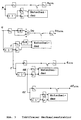
- Fig. 2 shows the learning modulation type recognizer with clock-free feature extraction.
- any step clock spectral line that may be present is discovered and the step clock time interval T is estimated therefrom.
- the coordinate transformation from Cartesian to polar coordinates a and ⁇ is carried out in the converter .
- the tactless feature extractor first determines the missing value sequences for D ⁇ , f, df, da and ddf.
- the relevant values are extracted by examining the respective derivative value sequence.
- the feature extractor is shown in more detail in Fig. 3 and described in the next section.
- the switch behind the clock-free feature extractor is set up for the learning phase of the modulation type recognizer, so that the learning branch is activated.
- the relevant characteristic values are accumulated in the accumulator and then normalized in the value range normalizer with regard to the following histogram generator with respect to the abscissa area. In Histogrammchanner histograms are for the parameters a, D ⁇ , f and df applied.
- the histograms are transformed from the original to the image area and only the first around 30% of the values are used. The remaining image area values are not required.
- block normalizer the image area results without regard to the respective first value are normalized with respect to the Ordinaten Gebe, and stored the respective resultant normalized image area values as reference functions in the reference function memory.
- the work phase is initiated by flipping the switch behind the tactless feature extractor .
- the signal sections to be analyzed automatically go through the same function blocks up to and including the normalizer as those already described for the learning phase.
- the image function sections resulting behind the normalizer are correlated in the correlator with the stored reference functions.
- Fig. 4 Details on the generation and use of the reference functions are shown in Fig. 4 and described below.
- the following quantities are input to the decision making: the correlation results, the numbers, the mean values and the standard deviations of the relevant parameters detected values from the Werte Schloniteern and optionally frequency value and power value of a detected in Spektralliniendetektor element timing spectral line.
- the modulation type decision is made from these parameters by comparison with predetermined threshold values, and is displayed or passed on to subsequent assemblies which depend on the result.
- Fig. 3 shows the basic structure of the tactless feature extractor.
- the extraction of the relevant values a SIVA (SIVA: Significant Values) for the amplitude a is shown in the upper part of the figure.
- the derivative is estimated in the functional element labeled () ' and the mean value of the derivative value sequence for the signal section under consideration is estimated in the element labeled ⁇ .
- the elements labeled ⁇ 1 and ⁇ 2 compensate for the runtime differences in the parallel branches.
- the decision maker checks the size of the deviation between the mean value and the instantaneous value of the derived value sequence and, in the event of a small deviation, closes the switch in the upper signal path.
- the limit values required for the decision are given to the decision maker .
- the decision maker selects the relevant amplitude values a SIVA .
- the functional element designated ⁇ 3 is intended to compensate for the difference in transit time from the arrangement shown in the lower part of the figure.
- the lower part of Fig. 3 explains the extraction of the relevant values for the quantities D ⁇ , f and df derived from phase ⁇ .
- the difference phase values D Differenz are determined from the phase values with the aid of the delay element denoted by ⁇ T and an adder. The adder is marked with the + symbol.
- the decision maker selects only those for which the temporally corresponding instantaneous values of the derivative f differ only slightly from the average derivative value.
- the extraction of the relevant difference phase values D ⁇ SIVA is basically identical to the extraction of a SIVA .
- the extraction of f SIVA and df SIVA shown in Fig. 3 below is carried out according to the same scheme as the extraction of a SIVA .
- the functional elements labeled ⁇ 4 and ⁇ 5 serve to balance the runtime, so that all four value sequences that are available for a SIVA , D ⁇ SIVA , f SIVA and df SIVA are available for further processing at the same time.
- Fig. 4 shows the principle of processing the characteristic histograms for a SIVA , D ⁇ SIVA , f SIVA and df SIVA .
- the characteristic considered by way of example has four relevant value states.
- the feature histogram for all values from n signal sections is shown in the upper part of the figure, where n> 1 was assumed here.
- H denotes the abbreviation for frequency and histo that for histogram.
- Such a relatively smooth histogram is obtained during the learning phase of the modulation type recognizer.
- the four relevant values are clearly visible.
- DFT the characteristic lines shown in the upper right part of the figure are obtained for the amounts in the image area.
- the line at the abscissa value 0 corresponds to the total frequency, which is not used for the subsequent correlation.
- the line at the abscissa value 4 is that which essentially describes the envelope of the underlying histogram.
- the smaller lines are a measure of the deviation of the histogram envelope from a sine wave.
- the dashed 10 lines are sufficient for the histogram characterization to be sufficiently precise.
- the line values 1 to 9 are normalized to the energy value one in the normalizer and stored as reference function values. In the manner shown, reference function values for all modulation types of interest and for all four parameters are determined and stored as part of the learning phase.
- the same signal processing is shown as in the upper part, but with a smaller underlying signal observation length.
- the histogram result from only one signal section corresponds to that which is typically present in the working phase of the modulation type recognizer.
- the comparatively short observation length or also due to smaller signal-to-interference ratios results in a rougher histogram shape. This is also reflected in the result after the DFT shown at the bottom right.
- This result is normalized in the normalizer without taking into account the line at the abscissa value 0 and correlated in the correlator with all stored reference functions.
- the correlation with all stored reference functions is indicated in Fig. 4 top right by several arrows pointing at the correlator . Due to the similarity of the two image function sections shown in the figure, this results in a relatively large correlation result, which clearly indicates the relationship of the two underlying feature histograms.
Landscapes
- Engineering & Computer Science (AREA)
- Computer Networks & Wireless Communication (AREA)
- Signal Processing (AREA)
- Radar Systems Or Details Thereof (AREA)
- Digital Transmission Methods That Use Modulated Carrier Waves (AREA)
Abstract
Description
- Abbildung 1
- die Stufen der Signalanalyse mit Modulationsartenerkenner,
- Abbildung 2
- die Funktion des lernenden Modulationsartenerkenners mit taktfreier Mermalsextraktion,
- Abbildung 3
- einen erfindungsgemäßen taktfreien Merkmalsextraktor,
- Abbildung 4
- eine adaptive Referenzfunktions-Bildung mit Korrelation.
Claims (6)
- Verfahren zur automatischen Erkennung von Signal-Modulationsarten mit unbekannten Parametern, bei dem aus dem empfangenen, komplex demodulierten, mit einem Tiefpaß gefilterten und digitalisierten Signal fortlaufend die Momentanwerte für Amplitude a und Phase ϕ entnommen und aus letzterer, die Differenzphasenwerte Dϕ und die Frequenzwerte f abgeleitet und daraus, bei Überschreitung vorgegebener Schwellenwerte, Histogramme für Amplitude, Differenzphase und Frequenz angelegt werden, welche, zusammen mit den Größen für Mittelwert und Varianz für Amplitude und Frequenz und mit einer gegebenenfalls hinter einer Betrags-Quadrierung mit nachfolgender Spektrumsbildung festgestellten Schrittakt-Spektrallinie zur Erkennung und Klassifizierung der Signal-Modulationsart des empfangenen Signals herangezogen werden,
gekennzeichnet durch die folgenden Verfahrensschritte:a) Das empfangene komplexe Basisbandsignal wird zusätzlich zur Betrags-Quadrierung noch einer komplexen Quadrierung unterzogen, wobei hinter beiden nichtlinearen Operationen eine Spektrumsbildung vorgenommen wird, um eine gegebenenfalls vorhandene Schrittakt-Spektrallinie aufzufinden, deren Frequenzwert durch Kehrwertbildung zum abzuschätzenden Schrittakt-Zeitintervall T führt, welches für die spätere Bestimmung von Differenzphasenwerten in einem Speicher aufbewahrt wird,b). aus den Signal-Phasenwerten werden zusätzlich zu den Frequenzwerten noch die Werte für die mathematische Ableitung der Frequenz df bestimmt,c) in einem taktfieien Merkmalsextraktor werden die mathematischen Ableitungen für die vorgenannten Wertefolgen a, Dϕ, f und df gebildet und die relevanten Werte aus a, Dϕ, f und df zu den Zeitpunkten extrahiert, zu denen die Werte der jeweils zugehörigen Ableitungswertefolge vorgegebene Abstandswerte von dem zugeordneten Mittelwert der Ableitungswertefolge für den betrachteten Signalabschnitt nicht überschreiten, wobei das für die Differenzphasenbildung benötigte Zeitintervall T entweder wie unter a) beschrieben oder, falls keine Schrittakt-Spektrallinie entdeckt wurde, mit Hilfe des Kehrwertes der bekannten Signalbandbreite bestimmt wird,d) nach der Akkumulation der relevanten Werte für a, Dϕ, f und df über einen oder, bei ausreichender Signaldauer, über mehrere Signalabschnitte hinweg und nach Bereichsnormierung mit Hilfe der jeweiligen Mittelwerte und Standardabweichungen und Verarbeitung der relevanten Parameterwerte zu Histogrammen werden aus diesen Histogrammen mittels Digitaler Fourier-Transformation Bildfunktionen bestimmt, die insgesamt oder ausschnittsweise bezüglich der Ordinate normiert und in dieser Form weiterverwendet werden,e) für vorgegebene Signalproben werden im Rahmen der Lernphase die normierten Bildfunktionen oder Bildfunktionsausschnitte für die vier Parameter a, Dϕ, f und df, die Anzahlen der relevanten Werte der genannten Parameter, Mittelwerte und Standardabweichungen sowie die Parameter von gegebenenfalls festgestellten Schrittakt-Spektrallinien als Referenzwerte für die vorgegebenen Modulationsarten abgespeichert,f) im Rahmen der Arbeitsphase werden in gleicher Weise gefundene und normierte Bildfunktionen oder Bildfunktionsausschnitte mittels Korrelation oder nach der Methode der Kleinsten quadratischen Abweichung mit den vorher gelernten Referenzfunktionen verglichen,g) die sich für die Bildfunktionen oder Bildfunktionsausschnitte der Parameter a, Dϕ, f und df ergebenden Korrelationsergebnisse bzw. quadratischen Abweichungen, die Anzahlen der relevanten Werte der genannten Parameter, ihre Mittelwerte und ihre Standardabweichungen werden unter Beachtung vorgegebener Toleranzbereiche geprüft und daraus, zusammen mit einer hinter der Betragsquadrierung oder der komplexen Quadrierung jeweils mit nachfolgender Spektrumsbildung gegebenenfalls gefundenen Schrittakt-Spektrallinie, auf die aktuell anliegende Modulationsart geschlossen. - Verfahren nach Anspruch 1,
dadurch gekennzeichnet,daß die sich aus den transformierten Merkmalshistogrammen ergebenden Bildfunktionen oder Bildfunktionsausschnitte mit Hilfe von nichtparametrischen Bewertungsmethoden wie einem Nächster-Nachbar-Klassifikator, einem Künstlichen Neuronalen Netz, einem Entscheidungsnetzwerk mit Fuzzy-Logik oder Kombinationen aus den genannten Methoden ausgewertet werden. - Verfahren nach einem der Ansprüche 1 oder 2,
dadurch gekennzeichnet,daß die modulationstypischen Histogramme und/oder die daraus mittels der Digitalen Fourier Transformation errechneten Bildfunktionen oder Bildfunktionsausschnitte auf einem Bildschirm angezeigt werden. - Verfahren nach einem der Ansprüche 1 bis 3,
dadurch gekennzeichnet,daß nach Anzeige von Zwischen- und/oder Endergebnissen, für einen interaktiven Analysebetrieb, eine Änderung von Parametern vorgenommen werden kann. - Verfahren nach einem der Ansprüche 1 bis 4,
dadurch gekennzeichnet,daß die Arbeitsphase abschnittsweise durch Lernphasen unterbrochen wird. - Verfahren nach einem der Anspüche 1 bis 5,
dadurch gekennzeichnet,daß der Vergleichsvorgang in der Arbeitsphase, alternativ oder wahlweise, auf fest vorgegebene Referenzfunktionen bezogen ist.
Applications Claiming Priority (2)
| Application Number | Priority Date | Filing Date | Title |
|---|---|---|---|
| DE19814770 | 1998-04-02 | ||
| DE19814770A DE19814770C1 (de) | 1998-04-02 | 1998-04-02 | Verfahren zur automatischen taktfreien Erkennung von Signal-Modulationsarten |
Publications (3)
| Publication Number | Publication Date |
|---|---|
| EP0948172A2 true EP0948172A2 (de) | 1999-10-06 |
| EP0948172A3 EP0948172A3 (de) | 2002-01-09 |
| EP0948172B1 EP0948172B1 (de) | 2004-08-18 |
Family
ID=7863347
Family Applications (1)
| Application Number | Title | Priority Date | Filing Date |
|---|---|---|---|
| EP99106431A Expired - Lifetime EP0948172B1 (de) | 1998-04-02 | 1999-03-29 | Verfahren zur automatischen taktfreien Erkennung von Signal-Modulationsarten |
Country Status (2)
| Country | Link |
|---|---|
| EP (1) | EP0948172B1 (de) |
| DE (2) | DE19814770C1 (de) |
Cited By (3)
| Publication number | Priority date | Publication date | Assignee | Title |
|---|---|---|---|---|
| US6191727B1 (en) * | 1998-12-09 | 2001-02-20 | L-3 Communications Corporation | System and method for detecting signals across radar and communications bands |
| WO2006024849A1 (en) * | 2004-09-01 | 2006-03-09 | Browne Robin Forsythe | Method and apparatus for identifying the modulation format of a received signal |
| DE10232195B4 (de) * | 2002-07-16 | 2015-03-05 | Rohde & Schwarz Gmbh & Co. Kg | Verfahren und Vorrichtung zum Messen der Symbolrate eines digital modulierten Hochfrequenzsignals |
Families Citing this family (3)
| Publication number | Priority date | Publication date | Assignee | Title |
|---|---|---|---|---|
| DE102005025402A1 (de) * | 2005-06-02 | 2006-12-07 | Rohde & Schwarz Gmbh & Co. Kg | Verfahren zur Klassifizierung von digital modulierten Signalen |
| DE102009035524B4 (de) * | 2009-07-31 | 2012-11-29 | Fraunhofer-Gesellschaft zur Förderung der angewandten Forschung e.V. | Verfahren zur Erkennung eines oder mehrerer Nutzsignale innerhalb eines Quellsignals |
| CN113518049B (zh) * | 2021-04-13 | 2024-04-26 | 江苏师范大学 | 一种基于分数低阶极坐标和深度学习的调制识别方法 |
Family Cites Families (3)
| Publication number | Priority date | Publication date | Assignee | Title |
|---|---|---|---|---|
| DE2752468A1 (de) * | 1977-11-24 | 1979-05-31 | Ferdinand Dipl Ing Liedtke | Verfahren zur automatischen erkennung phasengetasteter signale mit unbekannten parametern |
| DE3834377A1 (de) * | 1988-10-10 | 1990-04-12 | Medav Digitale Signalverarbeit | Verfahren zur automatischen erkennung und klassifizierung von digital quadratur-amplituden-modulierten signalen mit unbekannten parametern |
| DE4243113C2 (de) * | 1992-12-21 | 1996-08-29 | Medav Digitale Signalverarbeit | Verfahren zur automatischen, spektralen Einweisung von Modulationsart-Klassifikatoren |
-
1998
- 1998-04-02 DE DE19814770A patent/DE19814770C1/de not_active Expired - Fee Related
-
1999
- 1999-03-29 DE DE59910237T patent/DE59910237D1/de not_active Expired - Fee Related
- 1999-03-29 EP EP99106431A patent/EP0948172B1/de not_active Expired - Lifetime
Cited By (3)
| Publication number | Priority date | Publication date | Assignee | Title |
|---|---|---|---|---|
| US6191727B1 (en) * | 1998-12-09 | 2001-02-20 | L-3 Communications Corporation | System and method for detecting signals across radar and communications bands |
| DE10232195B4 (de) * | 2002-07-16 | 2015-03-05 | Rohde & Schwarz Gmbh & Co. Kg | Verfahren und Vorrichtung zum Messen der Symbolrate eines digital modulierten Hochfrequenzsignals |
| WO2006024849A1 (en) * | 2004-09-01 | 2006-03-09 | Browne Robin Forsythe | Method and apparatus for identifying the modulation format of a received signal |
Also Published As
| Publication number | Publication date |
|---|---|
| DE59910237D1 (de) | 2004-09-23 |
| EP0948172B1 (de) | 2004-08-18 |
| EP0948172A3 (de) | 2002-01-09 |
| DE19814770C1 (de) | 1999-09-23 |
Similar Documents
| Publication | Publication Date | Title |
|---|---|---|
| DE60033896T2 (de) | Unterscheidung von Modulationsarten | |
| DE2919085C2 (de) | Vorverarbeitungsverfahren und -vorrichtung für eine Spracherkennungsvorrichtung | |
| EP0544991B1 (de) | Verfahren zur automatischen Klassifikation digital modulierter Signale und Anordnung zum Ausführen des Verfahrens | |
| DE19504514C2 (de) | Verfahren zum Erfassen von Verarbeitungstönen | |
| EP0948172B1 (de) | Verfahren zur automatischen taktfreien Erkennung von Signal-Modulationsarten | |
| DE3929077C2 (de) | Verfahren und Einrichtung zur akustischen Identifikation und Klassifikation von Hubschraubern | |
| DE4102412C2 (de) | Verfahren zur Modulationsartenerkennung und Anordnung zum Ausführen des Verfahrens | |
| EP1825602B1 (de) | Vorrichtung und verfahren zum ermitteln eines korrelationsmaximums | |
| DE3834377C2 (de) | ||
| DE69206483T2 (de) | Modulare Beobachtungsanordnung zur Verkehrsbeobachtung von digitalen Signalen. | |
| EP0916206B1 (de) | Verfahren und anordnung zum beurteilen der qualität eines übertragenen sprachsignals | |
| DE3414929C2 (de) | Funküberwachungssystem | |
| DE102017129168A1 (de) | Verfahren zur Spektrumklassifizierung, Verfahren zur Klassifizierung sowie Empfangsvorrichtung | |
| DE69629643T2 (de) | Übertragungssystem mit verbesserter tonerkennung | |
| EP1126730B1 (de) | Verfahren zur aufwandsarmen Signal-, Ton- und Phasenwechseldetektion | |
| EP2603806B1 (de) | Verfahren und vorrichtung zum verhindern von signalflankenverlusten | |
| DE69622222T2 (de) | Nicht-beeinflussende Bestimmung der Übertragungsqualität auf Telephonleitungen | |
| EP2958242B1 (de) | Verfahren und vorrichtung zum verarbeiten eines rundfunksignals | |
| DE19746507B4 (de) | Verfahren zur Zuordnung eines Empfangssignals zu einer von mehreren Klassen von Modulationsarten | |
| DE102011052900B4 (de) | Verfahren und Vorrichtung zur Ein- und Zuordnung von Signalemittern in Echtzeit und deren Verwendung als Warnvorrichtung | |
| DE2515769A1 (de) | Frequenzselektiver signalempfaenger | |
| DE19541188C1 (de) | Verfahren zum Klassifizieren der Modulationsart eines Datensignals | |
| DE4243113C2 (de) | Verfahren zur automatischen, spektralen Einweisung von Modulationsart-Klassifikatoren | |
| DE10232195B4 (de) | Verfahren und Vorrichtung zum Messen der Symbolrate eines digital modulierten Hochfrequenzsignals | |
| DE10164118A1 (de) | Verfahren und Anordnung zur Erkennung von Frequenzsprungfolgesignalen |
Legal Events
| Date | Code | Title | Description |
|---|---|---|---|
| PUAI | Public reference made under article 153(3) epc to a published international application that has entered the european phase |
Free format text: ORIGINAL CODE: 0009012 |
|
| AK | Designated contracting states |
Kind code of ref document: A2 Designated state(s): AT BE CH CY DE DK ES FI FR GB GR IE IT LI LU MC NL PT SE Kind code of ref document: A2 Designated state(s): DE FR GB |
|
| AX | Request for extension of the european patent |
Free format text: AL;LT;LV;MK;RO;SI |
|
| PUAL | Search report despatched |
Free format text: ORIGINAL CODE: 0009013 |
|
| AK | Designated contracting states |
Kind code of ref document: A3 Designated state(s): AT BE CH CY DE DK ES FI FR GB GR IE IT LI LU MC NL PT SE |
|
| AX | Request for extension of the european patent |
Free format text: AL;LT;LV;MK;RO;SI |
|
| 17P | Request for examination filed |
Effective date: 20020117 |
|
| AKX | Designation fees paid |
Free format text: DE FR GB |
|
| GRAP | Despatch of communication of intention to grant a patent |
Free format text: ORIGINAL CODE: EPIDOSNIGR1 |
|
| GRAS | Grant fee paid |
Free format text: ORIGINAL CODE: EPIDOSNIGR3 |
|
| GRAA | (expected) grant |
Free format text: ORIGINAL CODE: 0009210 |
|
| AK | Designated contracting states |
Kind code of ref document: B1 Designated state(s): DE FR GB |
|
| REG | Reference to a national code |
Ref country code: GB Ref legal event code: FG4D Free format text: NOT ENGLISH |
|
| GBT | Gb: translation of ep patent filed (gb section 77(6)(a)/1977) |
Effective date: 20040818 |
|
| REG | Reference to a national code |
Ref country code: IE Ref legal event code: FG4D Free format text: GERMAN |
|
| REF | Corresponds to: |
Ref document number: 59910237 Country of ref document: DE Date of ref document: 20040923 Kind code of ref document: P |
|
| REG | Reference to a national code |
Ref country code: IE Ref legal event code: FD4D |
|
| ET | Fr: translation filed | ||
| PLBE | No opposition filed within time limit |
Free format text: ORIGINAL CODE: 0009261 |
|
| STAA | Information on the status of an ep patent application or granted ep patent |
Free format text: STATUS: NO OPPOSITION FILED WITHIN TIME LIMIT |
|
| 26N | No opposition filed |
Effective date: 20050519 |
|
| PGFP | Annual fee paid to national office [announced via postgrant information from national office to epo] |
Ref country code: GB Payment date: 20090324 Year of fee payment: 11 |
|
| PGFP | Annual fee paid to national office [announced via postgrant information from national office to epo] |
Ref country code: DE Payment date: 20090529 Year of fee payment: 11 |
|
| PGFP | Annual fee paid to national office [announced via postgrant information from national office to epo] |
Ref country code: FR Payment date: 20090318 Year of fee payment: 11 |
|
| GBPC | Gb: european patent ceased through non-payment of renewal fee |
Effective date: 20100329 |
|
| REG | Reference to a national code |
Ref country code: FR Ref legal event code: ST Effective date: 20101130 |
|
| PG25 | Lapsed in a contracting state [announced via postgrant information from national office to epo] |
Ref country code: FR Free format text: LAPSE BECAUSE OF NON-PAYMENT OF DUE FEES Effective date: 20100331 |
|
| PG25 | Lapsed in a contracting state [announced via postgrant information from national office to epo] |
Ref country code: DE Free format text: LAPSE BECAUSE OF NON-PAYMENT OF DUE FEES Effective date: 20101001 |
|
| PG25 | Lapsed in a contracting state [announced via postgrant information from national office to epo] |
Ref country code: GB Free format text: LAPSE BECAUSE OF NON-PAYMENT OF DUE FEES Effective date: 20100329 |