EP0948385B1 - Vorrichtung zur Komprimierung und Lagerung von Sauerstoff-angereichertem Gas - Google Patents
Vorrichtung zur Komprimierung und Lagerung von Sauerstoff-angereichertem Gas Download PDFInfo
- Publication number
- EP0948385B1 EP0948385B1 EP98948271A EP98948271A EP0948385B1 EP 0948385 B1 EP0948385 B1 EP 0948385B1 EP 98948271 A EP98948271 A EP 98948271A EP 98948271 A EP98948271 A EP 98948271A EP 0948385 B1 EP0948385 B1 EP 0948385B1
- Authority
- EP
- European Patent Office
- Prior art keywords
- oxygen
- pressure
- gas
- piston
- compressor
- Prior art date
- Legal status (The legal status is an assumption and is not a legal conclusion. Google has not performed a legal analysis and makes no representation as to the accuracy of the status listed.)
- Expired - Lifetime
Links
- 239000007789 gas Substances 0.000 title claims description 128
- QVGXLLKOCUKJST-UHFFFAOYSA-N atomic oxygen Chemical compound [O] QVGXLLKOCUKJST-UHFFFAOYSA-N 0.000 title claims description 111
- 239000001301 oxygen Substances 0.000 title claims description 111
- 229910052760 oxygen Inorganic materials 0.000 title claims description 111
- 238000003860 storage Methods 0.000 claims description 13
- MYMOFIZGZYHOMD-UHFFFAOYSA-N Dioxygen Chemical compound O=O MYMOFIZGZYHOMD-UHFFFAOYSA-N 0.000 claims description 7
- 229910001882 dioxygen Inorganic materials 0.000 claims description 5
- 238000012913 prioritisation Methods 0.000 claims description 4
- 239000003570 air Substances 0.000 description 22
- 230000006835 compression Effects 0.000 description 17
- 238000007906 compression Methods 0.000 description 17
- IJGRMHOSHXDMSA-UHFFFAOYSA-N Atomic nitrogen Chemical compound N#N IJGRMHOSHXDMSA-UHFFFAOYSA-N 0.000 description 10
- 239000000203 mixture Substances 0.000 description 9
- 238000000034 method Methods 0.000 description 8
- 229910021536 Zeolite Inorganic materials 0.000 description 7
- HNPSIPDUKPIQMN-UHFFFAOYSA-N dioxosilane;oxo(oxoalumanyloxy)alumane Chemical compound O=[Si]=O.O=[Al]O[Al]=O HNPSIPDUKPIQMN-UHFFFAOYSA-N 0.000 description 7
- 239000008246 gaseous mixture Substances 0.000 description 7
- 238000001179 sorption measurement Methods 0.000 description 7
- 239000010457 zeolite Substances 0.000 description 7
- 238000010926 purge Methods 0.000 description 6
- 238000010586 diagram Methods 0.000 description 5
- 239000002808 molecular sieve Substances 0.000 description 5
- 229910052757 nitrogen Inorganic materials 0.000 description 5
- 238000000926 separation method Methods 0.000 description 5
- URGAHOPLAPQHLN-UHFFFAOYSA-N sodium aluminosilicate Chemical compound [Na+].[Al+3].[O-][Si]([O-])=O.[O-][Si]([O-])=O URGAHOPLAPQHLN-UHFFFAOYSA-N 0.000 description 5
- 210000000707 wrist Anatomy 0.000 description 5
- 101100288173 Enterococcus faecalis (strain ATCC 700802 / V583) prs1 gene Proteins 0.000 description 4
- 101100465401 Saccharomyces cerevisiae (strain ATCC 204508 / S288c) SCL1 gene Proteins 0.000 description 4
- 230000000712 assembly Effects 0.000 description 4
- 238000000429 assembly Methods 0.000 description 4
- 230000000994 depressogenic effect Effects 0.000 description 4
- 239000000463 material Substances 0.000 description 4
- 239000011148 porous material Substances 0.000 description 4
- 101150016674 prs2 gene Proteins 0.000 description 4
- 230000007935 neutral effect Effects 0.000 description 3
- 101100298888 Arabidopsis thaliana PAD2 gene Proteins 0.000 description 2
- 101100030928 Arabidopsis thaliana PAF1 gene Proteins 0.000 description 2
- 101100465385 Arabidopsis thaliana PAF2 gene Proteins 0.000 description 2
- CURLTUGMZLYLDI-UHFFFAOYSA-N Carbon dioxide Chemical compound O=C=O CURLTUGMZLYLDI-UHFFFAOYSA-N 0.000 description 2
- 101100398338 Enterococcus faecalis (strain ATCC 700802 / V583) prs2 gene Proteins 0.000 description 2
- 101100510342 Listeria ivanovii prs gene Proteins 0.000 description 2
- 101100137870 Saccharomyces cerevisiae (strain ATCC 204508 / S288c) PRE10 gene Proteins 0.000 description 2
- 229920006362 Teflon® Polymers 0.000 description 2
- 239000000956 alloy Substances 0.000 description 2
- 229910045601 alloy Inorganic materials 0.000 description 2
- 238000004891 communication Methods 0.000 description 2
- 238000001816 cooling Methods 0.000 description 2
- 230000001419 dependent effect Effects 0.000 description 2
- 239000012530 fluid Substances 0.000 description 2
- 101150077839 pac1 gene Proteins 0.000 description 2
- 101150086435 prs1 gene Proteins 0.000 description 2
- 238000012546 transfer Methods 0.000 description 2
- OYPRJOBELJOOCE-UHFFFAOYSA-N Calcium Chemical group [Ca] OYPRJOBELJOOCE-UHFFFAOYSA-N 0.000 description 1
- UGFAIRIUMAVXCW-UHFFFAOYSA-N Carbon monoxide Chemical compound [O+]#[C-] UGFAIRIUMAVXCW-UHFFFAOYSA-N 0.000 description 1
- DGAQECJNVWCQMB-PUAWFVPOSA-M Ilexoside XXIX Chemical compound C[C@@H]1CC[C@@]2(CC[C@@]3(C(=CC[C@H]4[C@]3(CC[C@@H]5[C@@]4(CC[C@@H](C5(C)C)OS(=O)(=O)[O-])C)C)[C@@H]2[C@]1(C)O)C)C(=O)O[C@H]6[C@@H]([C@H]([C@@H]([C@H](O6)CO)O)O)O.[Na+] DGAQECJNVWCQMB-PUAWFVPOSA-M 0.000 description 1
- 239000003463 adsorbent Substances 0.000 description 1
- 229910052782 aluminium Inorganic materials 0.000 description 1
- 239000012080 ambient air Substances 0.000 description 1
- 239000003990 capacitor Substances 0.000 description 1
- 229910002092 carbon dioxide Inorganic materials 0.000 description 1
- 239000001569 carbon dioxide Substances 0.000 description 1
- 229910002091 carbon monoxide Inorganic materials 0.000 description 1
- 238000005352 clarification Methods 0.000 description 1
- 239000004020 conductor Substances 0.000 description 1
- 230000001351 cycling effect Effects 0.000 description 1
- 230000007423 decrease Effects 0.000 description 1
- 230000003247 decreasing effect Effects 0.000 description 1
- 238000009792 diffusion process Methods 0.000 description 1
- -1 e.g. Substances 0.000 description 1
- 230000000694 effects Effects 0.000 description 1
- 239000000835 fiber Substances 0.000 description 1
- 239000002783 friction material Substances 0.000 description 1
- 238000012423 maintenance Methods 0.000 description 1
- 238000004519 manufacturing process Methods 0.000 description 1
- 230000013011 mating Effects 0.000 description 1
- 238000012856 packing Methods 0.000 description 1
- 230000002093 peripheral effect Effects 0.000 description 1
- 230000003252 repetitive effect Effects 0.000 description 1
- 230000029058 respiratory gaseous exchange Effects 0.000 description 1
- 230000002441 reversible effect Effects 0.000 description 1
- 238000012163 sequencing technique Methods 0.000 description 1
- 239000011734 sodium Substances 0.000 description 1
- 229910052708 sodium Inorganic materials 0.000 description 1
- 238000013022 venting Methods 0.000 description 1
- XLYOFNOQVPJJNP-UHFFFAOYSA-N water Chemical compound O XLYOFNOQVPJJNP-UHFFFAOYSA-N 0.000 description 1
Images


Classifications
-
- A—HUMAN NECESSITIES
- A62—LIFE-SAVING; FIRE-FIGHTING
- A62B—DEVICES, APPARATUS OR METHODS FOR LIFE-SAVING
- A62B7/00—Respiratory apparatus
- A62B7/14—Respiratory apparatus for high-altitude aircraft
-
- A—HUMAN NECESSITIES
- A61—MEDICAL OR VETERINARY SCIENCE; HYGIENE
- A61M—DEVICES FOR INTRODUCING MEDIA INTO, OR ONTO, THE BODY; DEVICES FOR TRANSDUCING BODY MEDIA OR FOR TAKING MEDIA FROM THE BODY; DEVICES FOR PRODUCING OR ENDING SLEEP OR STUPOR
- A61M16/00—Devices for influencing the respiratory system of patients by gas treatment, e.g. ventilators; Tracheal tubes
- A61M16/10—Preparation of respiratory gases or vapours
- A61M16/1005—Preparation of respiratory gases or vapours with O2 features or with parameter measurement
- A61M16/101—Preparation of respiratory gases or vapours with O2 features or with parameter measurement using an oxygen concentrator
-
- B—PERFORMING OPERATIONS; TRANSPORTING
- B01—PHYSICAL OR CHEMICAL PROCESSES OR APPARATUS IN GENERAL
- B01D—SEPARATION
- B01D53/00—Separation of gases or vapours; Recovering vapours of volatile solvents from gases; Chemical or biological purification of waste gases, e.g. engine exhaust gases, smoke, fumes, flue gases, aerosols
- B01D53/02—Separation of gases or vapours; Recovering vapours of volatile solvents from gases; Chemical or biological purification of waste gases, e.g. engine exhaust gases, smoke, fumes, flue gases, aerosols by adsorption, e.g. preparative gas chromatography
- B01D53/04—Separation of gases or vapours; Recovering vapours of volatile solvents from gases; Chemical or biological purification of waste gases, e.g. engine exhaust gases, smoke, fumes, flue gases, aerosols by adsorption, e.g. preparative gas chromatography with stationary adsorbents
-
- F—MECHANICAL ENGINEERING; LIGHTING; HEATING; WEAPONS; BLASTING
- F04—POSITIVE - DISPLACEMENT MACHINES FOR LIQUIDS; PUMPS FOR LIQUIDS OR ELASTIC FLUIDS
- F04B—POSITIVE-DISPLACEMENT MACHINES FOR LIQUIDS; PUMPS
- F04B25/00—Multi-stage pumps
-
- F—MECHANICAL ENGINEERING; LIGHTING; HEATING; WEAPONS; BLASTING
- F04—POSITIVE - DISPLACEMENT MACHINES FOR LIQUIDS; PUMPS FOR LIQUIDS OR ELASTIC FLUIDS
- F04B—POSITIVE-DISPLACEMENT MACHINES FOR LIQUIDS; PUMPS
- F04B25/00—Multi-stage pumps
- F04B25/02—Multi-stage pumps of stepped piston type
-
- A—HUMAN NECESSITIES
- A61—MEDICAL OR VETERINARY SCIENCE; HYGIENE
- A61M—DEVICES FOR INTRODUCING MEDIA INTO, OR ONTO, THE BODY; DEVICES FOR TRANSDUCING BODY MEDIA OR FOR TAKING MEDIA FROM THE BODY; DEVICES FOR PRODUCING OR ENDING SLEEP OR STUPOR
- A61M16/00—Devices for influencing the respiratory system of patients by gas treatment, e.g. ventilators; Tracheal tubes
- A61M16/10—Preparation of respiratory gases or vapours
- A61M16/1005—Preparation of respiratory gases or vapours with O2 features or with parameter measurement
- A61M2016/102—Measuring a parameter of the content of the delivered gas
- A61M2016/1025—Measuring a parameter of the content of the delivered gas the O2 concentration
-
- B—PERFORMING OPERATIONS; TRANSPORTING
- B01—PHYSICAL OR CHEMICAL PROCESSES OR APPARATUS IN GENERAL
- B01D—SEPARATION
- B01D2253/00—Adsorbents used in seperation treatment of gases and vapours
- B01D2253/10—Inorganic adsorbents
-
- B—PERFORMING OPERATIONS; TRANSPORTING
- B01—PHYSICAL OR CHEMICAL PROCESSES OR APPARATUS IN GENERAL
- B01D—SEPARATION
- B01D2256/00—Main component in the product gas stream after treatment
- B01D2256/12—Oxygen
-
- B—PERFORMING OPERATIONS; TRANSPORTING
- B01—PHYSICAL OR CHEMICAL PROCESSES OR APPARATUS IN GENERAL
- B01D—SEPARATION
- B01D2259/00—Type of treatment
- B01D2259/45—Gas separation or purification devices adapted for specific applications
- B01D2259/4533—Gas separation or purification devices adapted for specific applications for medical purposes
-
- B—PERFORMING OPERATIONS; TRANSPORTING
- B01—PHYSICAL OR CHEMICAL PROCESSES OR APPARATUS IN GENERAL
- B01D—SEPARATION
- B01D2259/00—Type of treatment
- B01D2259/45—Gas separation or purification devices adapted for specific applications
- B01D2259/4541—Gas separation or purification devices adapted for specific applications for portable use, e.g. gas masks
-
- B—PERFORMING OPERATIONS; TRANSPORTING
- B01—PHYSICAL OR CHEMICAL PROCESSES OR APPARATUS IN GENERAL
- B01D—SEPARATION
- B01D53/00—Separation of gases or vapours; Recovering vapours of volatile solvents from gases; Chemical or biological purification of waste gases, e.g. engine exhaust gases, smoke, fumes, flue gases, aerosols
- B01D53/02—Separation of gases or vapours; Recovering vapours of volatile solvents from gases; Chemical or biological purification of waste gases, e.g. engine exhaust gases, smoke, fumes, flue gases, aerosols by adsorption, e.g. preparative gas chromatography
- B01D53/04—Separation of gases or vapours; Recovering vapours of volatile solvents from gases; Chemical or biological purification of waste gases, e.g. engine exhaust gases, smoke, fumes, flue gases, aerosols by adsorption, e.g. preparative gas chromatography with stationary adsorbents
- B01D53/0407—Constructional details of adsorbing systems
- B01D53/0446—Means for feeding or distributing gases
Definitions
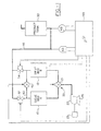
- the apparatus includes one or more, and preferably two beds 10 and 12 which contain a physical separation medium or material.
- the separation material selectively adsorbs one or more adsorbable components as from air and passes one or more nonadsorbable components of such a gaseous mixture.
- the physical separation material can be a molecular sieve with pores of uniform size and essentially the same molecular dimensions. These pores selectively adsorb molecules in accordance with molecular shape, polarity, degree of saturation, and the like.
- the physical separation medium is an aluminasilicate composition with 4 to 5 A (Angstrom) pores.
- the molecular sieve is a sodium or calcium form of aluminasilicate, such as type 5A zeolite.
- the aluminasilicate may have a higher silicon-to-aluminum ratio, larger pores, and an affinity for polar molecules, e.g., type 13x zeolite.
- the zeolite adsorbs nitrogen, carbon monoxide, carbon dioxide, water vapor, and other significant components of air.
- Compressor 22 which receives air from inlet 23, is connected to a first drive motor 25, in the preferred embodiment about a 1 ⁇ 4-horsepower electric motor.
- a solenoid (not shown) or other cross-over valve actuating means selectively causes the cross-over valving means to move alternately between first and second positions.
- the first position the first bed 10 is connected with compressor 22 to cause nitrogen adsorption and oxygen enrichment in the product gas, and the second bed 12 is vented to atmosphere to allow evacuation.
- the first bed In the second position, the first bed is vented to atmosphere to allow evacuation and the second bed is connected with the air compressor to cause nitrogen adsorption.
- the invention is described with specific reference to a pressure-swing control. However, it is equally applicable to other methods of sequencing the gas flow through the sieve beds such as a timing-based system.
- the composition of the gas in the voids of the zeolite varies from substantially pure primary-product gas at the outlet end, to the ambient gaseous mixture composition at the inlet end.
- an adsorption zone of finite, relatively large size is formed as the gas mixture is introduced through a bed inlet to an adsorbed, gas-free or regenerated bed.
- This adsorption zone is a region of the bed in which the full capacity of the adsorbent to hold the adsorbable components has not been reached.
- This adsorption zone moves from the bed inlet toward a bed outlet with a velocity significantly less than the superficial gas velocity in the bed.
- the breakthrough is defined by the size and configuration of the bed container as well as the packing configuration of the molecular sieve and the flow rate and bed gas pressure.
- the configuration of the bed is generally cylindrical and the output volume rate can vary from about 0.1 to 6 liters per minute.
- the breakthrough is the time required for the diffusion reaction as the nitrogen saturates and is weakly bonded to the sieve bed.
- primary product-enriched bed gas in the zeolite voids varies from a higher primary product gas concentration at the bed outlet to a lower concentration at the bed inlet.
- the primary product-enriched bed gas is about 80 percent primary product at breakthrough. While adsorption is occurring in one bed, the adsorbable components adsorbed by the separation medium of the other bed are purged from the other bed because of the drop in pressure due to atmospheric venting and because of exposure to relatively pure product gas from the first tank.
- the first bed 10 is connected with a reservoir or product tank 30 by way of a first check valve 32 or other unidirectional valving means.
- the first check valve 32 permits the primary product gas from the first bed 10 to flow into the reservoir or product tank 30 via line 46 when the product gas pressure in the first bed 10 exceeds the pressure of product gas in the reservoir or product tank 30.
- the first check valve prohibits the product gas from flowing from the reservoir or product tank 30 when the pressure in the first bed 10 is lower than the reservoir or product tank. More specific to the preferred embodiment, the check valve imposes a 1.5 psi bias such that flow is only permitted when the pressure in the first bed exceeds the pressure in the reservoir or product tank by 1.5 psi.
- the second bed 12 is connected with the reservoir or product tank 30 by way of a second check valve 34 or other unidirectional valving means.
- the second check valve 34 again provides for unidirectional flow of the primary product gas from the second bed 12 to the reservoir or product tank 30.
- a pressure equalization flow path 40 extends between outlets of the first and second beds.
- a concentration equalization valve 42 is either open or closed to selectively permit or prevent gas flow through the flow path between the first and second beds.
- a control means 50 cyclically causes the cross-over valve actuating means (i.e., two solenoids) and the concentration equalization valve 42 to be operated. The control means periodically and cyclically enables a concentration equalization valve actuator which is also a solenoid.
- Oxygen sensor 43 registers the oxygen concentration of the product gas and can be located in the product tank 30.
- the sensor 43 communicates a sensed value to the microprocessor (i.e., control means).
- a pressure sensor 45 registers the pressure in the product tank and communicates the same to the microprocessor.
- the control means causes the cross-over valving means 20 to alternate between its first and second positions for the appropriate period during each cycle segment.
- a cycle segment can be either the product gas generation cycle or the purge cycle.
- the cycle duration is selected such that each bed is connected with the source of air for a period of time which is equal to or less than the breakthrough time.
- the mechanism which triggers the cross-over valving can be based on the pressure, such as a pressure set point or set point range, in the bleed line from the product tank as is used in a pressure-based control cycle, or it can be based strictly on a residence time from the product-producing bed, such as in a timing cycle-based control cycle.
- the cross-over valving means 20 is actuated to reverse its position. Actuating the cross-over valving means discontinues supplying of the gaseous mixture to the first bed and commences evacuating it and concurrently discontinues evacuating the second bed and commences supplying it with the gaseous mixture.
- the concentration equalization valve 42 is opened allowing the primary product-enriched gas in the zeolite voids of the second bed to flow to the first bed. While the primary product-enriched gas is flowing to the first bed, the cross-over valving means is actuated. Actuating the cross-over valving means discontinues the evacuation of the first bed and commences supplying the gaseous mixture and concurrently discontinues supplying the gaseous mixture to the second bed and commences evacuating it. Subsequent to actuating the cross-over valving means, the concentration equalization valve is closed terminating the pressure equalizing flow of the primary product-enriched gas between the beds. The steps are cyclically repeated to provide continuing fractionating of the primary product gas from the mixture.
- Compressor 100 in a manner described below, compresses the oxygen-enriched gas to a pressure of about 2,250 psi and stores it within a mobile or portable cylinder 500.
- the feed pressure thereto can range from 21 psi down to a predetermined cut-off pressure such as about 5 or 7 psi whereupon the compressor is automatically shut off by a pressure sensor switch.
- FIGS. 3 and 4 relate to embodiments wherein oxygen-enriched air from product tank 30 of the oxygenator is fed by various methods desirably to a buffer tank of the compressor but prioritized as with regard to oxygen concentration and/or a sufficient pressure.
- the feed rate to a patient can vary from between 0.1 and 6 liters per minute at a pressure of a predetermined value such as 5 psi with the remaining oxygen-enriched gas generally being fed at a different pressure to the buffer tank.
- the buffer tank can generally contain a broad range of pressure therein such as, for example, between 14 and 21 psi.
- the pressure thereof can drop down to a predetermined cut-off pressure. such as 7 psi, which is higher than the pressure of the gas being fed to the patient to ensure an adequate flow of the oxygen-enriched gas to the patient.
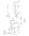
- a 5-psi regulator 210 emits oxygen-enriched gas from product tank 30 into flow line 220 and feeds the same to flow meter 230 which subsequently emits the oxygen-enriched gas to the patient at a predetermined flow rate of from 0.1 to 6 liters per minute.
- the flow meter can be closed so that all the enriched oxygen is directed to the compressor.
- Gas not directed to the patient is carried via line 240 to two-way valve 250.
- a very small portion of the gas in line 220 is directed through line 260 through restrictor 262 into oxygen sensor 265 which detects whether or not the concentration of the oxygen is of a predetermined value such as is at least 84 percent.
- two-way valve 250 When the oxygen sensor detects a concentration at or above the predetermined level, two-way valve 250 is open and permits the oxygen-enriched gas to flow through line 270 into buffer tank 200 wherein the pressure is essentially the same as the oxygen product tank pressure. However, should the oxygen sensor not detect a suitable oxygen concentration, two-way valve 250 is closed so that the oxygen concentrator can build up a sufficient oxygen concentration. This arrangement prioritizes the flow of oxygen-enriched gas so that the patient is assured of receiving a gas having a minimum oxygen concentration therein.
- Buffer tank 200 can have a regulator 280 thereon generally set at 12 psi to admit the oxygen-enriched gas to the compressor when needed. Alternatively, the pressure regulator can be set at anywhere from about 13 to about 21 psi.
- Restrictor 290 controls the flow rate of gas from the buffer tank to the compressor. Should the compressor drop the pressure in the buffer tank to below a predetermined value, a pressure sensor (not shown) will automatically cut off the flow of gas at a pressure above the pressure of the gas being fed to the patient. This prioritization assures that the patient receives priority with regard to oxygen-enriched gas.
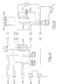
- FIG. 4 emits the oxygen-enriched gas through a 14 to about an 18-psi regulator 300 into flow line 305 having flow rate restrictor 307.
- the flow is then split with a portion via line 310 going through 5-psi regulator 320 and into flow meter 330 which then directs the gas to the patient at a desired flow rate of generally from 0.1 to 6 liters per minute, although optionally the flow meter can be closed.
- the remaining portion of the gas is directed via line 340 to two-way valve 350.
- a small portion of the gas going to the patient is diverted through line 365 through flow restrictor 367 to oxygen sensor 360.
- the oxygen sensor is set at a predetermined value such as a concentration of 84 percent so that when the level is not achieved, two-way valve 350 is closed through electrical line 355.
- a predetermined value such as a concentration of 84 percent
- the concentration of oxygen to ensure that the patient receives an amount of oxygen of at least the minimum predetermined value.
- the gas flows through two-way valve 350 into line 370 and into buffer tank 200 where it is stored generally at a pressure of about 14 to 18 psi.
- a relief valve 385 which can be set at any desired value such as about 14 psi ensures that gas under sufficient pressure is being admitted to the buffer tank.
- the oxygen-enriched gas is admitted to the compressor via line 380.
- a pressure sensor switch (not shown) can be set to a predetermined value (e.g., about 7 psi) to ensure or prioritize that a sufficient amount or flow of gas is being fed to the patient.
- the predetermined shut-off pressure of the compressor is always above the pressure of the gas being fed to the patient. The embodiment of FIG. 4 is preferred.
- FIGS. 2, 3, and 4 generally constitutes a preferred embodiment of the present invention
- oxygen product tank 30 need not be utilized.
- the oxygen-enriched air from an oxygen concentrator, such as shown in FIG. 1 can be fed to the buffer tank via the shown and described flow lines of the various embodiments such as set forth in FIGS. 2, 3, and 4. Accordingly, the oxygen-enriched air will be separated with one component directed to the patient and the other component being directed to the buffer tank. Prioritization of the oxygen-enriched gas to the patient either by a minimum oxygen concentration or a sufficient pressure in the buffer tank is still generally utilized.
- an enriched oxygen product tank 30 can be utili7ed and the buffer tank can optionally be eliminated.
- enriched oxygen from the product tank can be fed via one component to the patient and to a second component via the flow line shown to the compressor. In this situation, prioritization of the desired flow and oxygen concentration to the patient is maintained as described hereinabove with regard to either the level of oxygen concentration or an adequate pressure being admitted to the compressor.
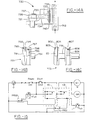
- the compressor assembly 100 as shown in FIGS. 7 and 8, it generally utilizes an AC electric-drive motor 105 which can rotate at any desired speed, e.g., 1,700 rpm.
- Motor 105 can contain a fan (not shown) either within the motor housing or immediately adjacent thereto to draw air through the motor to cool the same.
- Power is conveyed from the motor through shaft 106 to drive wheel 107.
- the drive wheel has a plurality of grooves therein to receive a V-belt such as main drive belt 109.
- Such belts are generally reinforced with fiber and have a very long life.
- Main drive belt 109 is connected to main gear 110 which contains a plurality of grooves 113 therein.
- peripheral grooves 113 coincides with the grooves of drive wheel 107 and matingly engage a plurality of projections located on main drive belt 109.
- Extending from main gear 110 is an offset hub gear 114 which has a much smaller diameter than main gear 110.
- Hub gear 114 also has grooves 115 thereon to receive a secondary drive V-belt 122.
- a second or secondary large gear 116 has grooves on the periphery thereof which matingly engage the secondary drive V-belt 122.
- Offset hub 114 through the secondary V-drive belt 122 contacts and serves to drive secondary gear 116 which in turn is connected to crankshaft 130.
- crankshaft 130 is a desirably low speed such as approximately 50 rpm.
- Both drive belts 109 and 122 desirably have a spring-loaded idler arm 125 and 127, respectively, which applies a small amount of tension.
- the actual pull tension of the first belt can be about 20 pounds, whereas the tension on the second belt can be about 100 pounds.
- the multi-stage compressor of the present invention can have any number of pistons, but in the present embodiment has three. As shown in FIG. 8, two of the pistons, i.e., the first and third pistons, are located on the same crankshaft lobe, whereas the second piston is located on a different lobe offset 180° from the first and third pistons. The reason for this is that pistons one and three will be drawing in air when the second piston is being compressed and vice versa.
- a crankshaft can be utilized which contains three lobes thereon, each offset from one another by approximately 110° to 130°, e.g., about 120°, so as to minimize the torque resistance applied to the motor during the compression stroke.
- the compressor of the present invention has three pistons, i.e., piston #1 (131), piston #2 (133), and piston #3 (135). Each piston is contained within a separate cylinder and thus piston #1 is contained within the first cylinder (132), the second piston is contained the second cylinder (134), and the third piston is contained within the third cylinder (136). While the diameter of the head 140 of the first piston is approximately equal to the diameter of the base portion of the piston as shown in FIGS. 8 and 9, the diameter of the head of piston #2 (133) is smaller than that of piston #1, and the diameter of the head of piston #3 (135) is smaller than the diameter of piston #2 (133). However, the base of each piston 131B, 133B, and 135B is of the same size for reasons set forth hereinbelow. In order to permit pistons #2 and #3 to operate properly, each contains an annular sleeve 134S and 136S on the inside of the cylinder wall the internal diameter of which is approximately equal to the external diameter of piston heads #2 and #3 respectively.
- the piston head has two annular grooves or recesses therein, that is top piston annulus 141 and bottom annulus 144.
- the top annulus contains a U-shaped seal therein generally made out of a Teflon® alloy or other low-friction material.
- the seal contains a coil tension spring 143 therein which forces the seal radially outward against the cylinder wall to prevent compressed air from leaking through the piston head between the piston and the cylinder wall.
- seal 142 is U-shaped so that upon the build-up of pressure in the cylinder head, the compressed gas will communicate and enter into the seal and force the outer edge thereof radially outward against the cylinder wall.
- Piston head bottom annulus 144 contains a flat or vertical glide ring 145 which extends around the annulus and is also radially forced outwardly by a coil tension spring 146 located therein.
- the bottom glide ring 145 can be made out of a Teflon® alloy and serves as a piston glide ring.
- Connecting rod 148 connects the piston head to piston base 150.
- the piston bases of all three pistons are the same diameter and accordingly engage a mating cylinder of essentially the same diameter.
- the piston base contains an upper base annulus 151 and a lower base annulus 155, both of which have a glide ring therein similar to if not identical to glide ring 145 of piston head annulus 144.
- upper base annulus 151 has a glide ring 152 therein which is forced radially outward by coil spring 153.
- lower base annulus 155 has a glide ring 156 therein which is radially forced out by coil spring 157.
- Piston base 150 contains bore 158 which extends laterally therethrough. Bore 158 receives wrist pin 159. The wrist pin and coil spring both serve to maintain glide ring 156 in a radially outward position so as to bear against the cylinder wall.
- the two-part piston assembly of the present invention contains bottom connecting rod 160 as shown in FIG. 10.
- the connecting rod contains a top bore 161 through which wrist pin 159 extends.
- Bottom bore 163 of the connecting rod extends about and matingly engages an appropriate portion of the crankshaft.
- sealed portion 164 of the connecting rod contains bearings therein.
- the net result of the two-part piston ring assembly of the present invention is that bearing 164 of connecting rod 160 can freely rotate with the crankshaft in a rotary or circular motion whereas top bore 161 moves in only a linear or reciprocal motion allowing piston rod 148 with the piston head and base thereon to move only in a linear reciprocating direction. The same thus prevents lateral forces from being applied to the cylinder wall which often results in wear and can create an oval-shaped cylinder wall.
- the two-part piston ring assembly of the present invention thus promotes long life of the piston and cylinder wall.
- cooling line 182 from the first piston to the second piston can be in the form of an undulating path or the like and the same is true with regard to cooling line 184 between the second and third pistons.
- Rupture disk 180 is a safety feature designed to rupture at a pressure in excess of the desired storage pressure of the gas cylinder. Thus, in the present embodiment, such a pressure can be approximately 2,800 psi. Although not shown, rupture disks can also be provided in the flow lines from the exit of the first and second cylinders to prevent undue build-up in these lines.
- a pressure regulator 181 serves to emit the oxygen-enriched gas at a pressure of about 5 psi to a patient via a flow meter (not shown) at any desired rate, such as from about 0.1 to about 6 liters per minute.
- One of these closed switches passes the power to high pressure switch 650 which is normally closed when the output pressure of the compressor is under 2,250 psi.
- the output of the high pressure switch is fed back to the start relay coil to keep the coil energized without the start switch being depressed, but will cut power to the coil when high pressure is reached. (This occurs when a tank has been filled.)
- the output of the high pressure switch is also connected to the common of low pressure switch 660. While the input pressure from the concentrator is above the predetermined value, e.g., 7 psi, the low pressure switch is closed and the normally closed contact has power. This power signal is fed to the drive contact of the solid-state relay which, in turn, allows the solid-state output to be "turned on.”
- the output of the high-pressure switch is also connected to the run indicator 670 which then lights up.
- the compact and lightweight compressor assembly 700 can achieve any desirable final pressure (e.g., from about 500 to about 3.000 PSI) such as that required for a compressed gas container and especially a compressed oxygen enriched bottle for use by a patient. In the embodiment shown and described, a final pressure of approximately 2,000 PSI is often preferred. Accordingly, wobble piston 732, while having a short stroke but a large piston head, generally receives enriched oxygen from product tank 30 or buffer tank 200 through a restrictor at any desired pressure such as about 10 PSI and compresses it to about 60 PSI.
- any desirable final pressure e.g., from about 500 to about 3.000 PSI
- a final pressure of approximately 2,000 PSI is often preferred.
- wobble piston 732 while having a short stroke but a large piston head, generally receives enriched oxygen from product tank 30 or buffer tank 200 through a restrictor at any desired pressure such as about 10 PSI and compresses it to about 60 PSI.
- an accumulator tank 785 between the first piston assembly and the second piston assembly 750 to store up the compressed gas produced by the wobble piston inasmuch as it reciprocates approximately six times for every one reciprocation of the second and third pistons.
- This tank can be a conventional tank such as a cylindrical tank, or desirably it can be in the form of a long thick but wide hose 785.
- Compressed gas from the wobble piston assembly which is operated by first power source 705, is transferred to second cylinder manifold 762, where it is compressed by the second piston, operated by second drive shaft 718, to a pressure of approximately 400 PSI. From there it is transferred via line 787 to the input of third cylinder manifold 782 whereupon it is compressed by the third piston, which also is driven by second drive shaft 718, to a pressure of approximately 2,000 PSI.
- each subsequent piston head is generally decreased. It is to be understood that generally any desirable head diameter can be utilized.
- the diameter of the wobble piston is generally about 1.8 inches.
- the diameter of the second piston head can be approximately 0.875 inches, whereas the diameter of the third piston head is approximately 0.25 inches.
- the second and third pistons can have a stroke of approximately 1.25 inches, whereas the wobble piston can have a stroke of approximately 0.375 inch.
- the embodiment of FIG. 11 through 15 also contain check valves, generally before and after each cylinder, to prevent the oxygen enriched gas from being pushed backwards into the preceding cylinder or into the product or buffer tank.
- An advantage of the compressor of Figs. 11-15 is that it generally is compact and small, approximately 1/3 the size of the embodiment of the compressor shown in FIG 8, and also approximately 1/3 the weight thereof, so that it can weight only about 40 pounds. Due to the compactness of the alternative compressor, it can be mounted directly or on top of the oxygen concentrator or it can be made an integral part thereof.
- Bottle cylinder or high pressure storage container 820 can generally be of any size and contain any pressure although the above noted pressure of approximately 2,000 PSI is desirable.
- a small bottle of approximately 62 cubic inches can last a patient for approximately two hours. This time can be extended to approximately six hours when utilized in conjunction with a conserving device.
- a large tank of approximately 283 cubic inches can generally last a patient for approximately eight hours or approximately twenty-four hours when utilized with a conserving device.
- Manifold block 810 is located between third piston assembly 770 and bottle 820.
- the manifold block contains pressure gauge 812 and a high pressure switch which, as explained herein below, turns off the compressor once a predetermined pressure is achieved.
- the manifold also contains a ruptured disc, not shown, as a safety backup should the pressure to the bottle become too high.
- the manifold block also contains a bleed-off valve, not shown, which gradually releases the pressure built up in compressor assembly 700 as well as line 789 so that a loud abrupt pressure release noise is not caused.
- Bottle 820 also contains a ruptured disc thereon, not shown, which is set to rupture at a pressure higher than that of the manifold rupture disc.
- the bottle can also contain a pressure gauge 822.
- the compact compressor 700 can be utilized in the same manner as before, that is in association with an oxygenator and with various flow schemes, designs, etc., whether prioritized to insure that a patient receives a required amount of the oxygen enriched gas, or not prioritized. Accordingly, the flow diagrams of FIGS. 2, 3 or 4, can be utilized but it is to be understood that generally any other flow system can also be utilized to route the enriched oxygen from product tank 30 either directly, or indirectly, etc., to the buffer tank and to compact compressor 700.
- Mains power (line voltage) is supplied through a three conductor grounded line cord.
- the hot side of the mains power is connected to a resettable thermal circuit breaker.
- the output lead of the circuit breaker feeds the mains power on/off switch.
- the neutral side of the mains power is supplied to one side of the High Pressure switch PRS2, Low Pressure switch PRS1, the "Run" light L1, hourmeter HM1, and the compressor motor M1.
- Low Pressure switch PRS1 If the Low Pressure switch PRS1 is activated by sensing pressure above its setpoint, K2 is energized, supplying power to the hourmeter and the compressor motor.
- PRS2 will activate, removing neutral power from the coil of latching relay K1 and lighting the "Full” light L2. This will remove power from the K1 coil, causing the latching and motor relays K1 and K2 to be de-energized, stopping the compressor motor and turning off the "Run” light L1.
Landscapes
- Health & Medical Sciences (AREA)
- Engineering & Computer Science (AREA)
- General Health & Medical Sciences (AREA)
- Emergency Medicine (AREA)
- Pulmonology (AREA)
- Veterinary Medicine (AREA)
- Mechanical Engineering (AREA)
- Hematology (AREA)
- Life Sciences & Earth Sciences (AREA)
- Animal Behavior & Ethology (AREA)
- Biomedical Technology (AREA)
- Public Health (AREA)
- Anesthesiology (AREA)
- Chemical & Material Sciences (AREA)
- Heart & Thoracic Surgery (AREA)
- General Engineering & Computer Science (AREA)
- Analytical Chemistry (AREA)
- Chemical Kinetics & Catalysis (AREA)
- Business, Economics & Management (AREA)
- Emergency Management (AREA)
- Oil, Petroleum & Natural Gas (AREA)
- General Chemical & Material Sciences (AREA)
- Separation Of Gases By Adsorption (AREA)
- Oxygen, Ozone, And Oxides In General (AREA)
- Compressor (AREA)
Claims (8)
- Vorrichtung zur Komprimierung und Speicherung von mit Sauerstoff angereichertem Gas, umfassend:einen Sauerstoffkonzentrator-Produkttank (30) mit angereichertem Sauerstoffgas zur Versorgung eines Patienten und einen Kompressor (100), der betriebsmäßig mit dem Sauerstoffkonzentrator-Produkttank verbunden ist, um mit Sauerstoff angereichertes Gas von diesem aufzunehmen und mit Sauerstoff angereichertes Hochdruck-Gas auszugeben undeinen Hochdruck-Speicherbehälter (500) für die tragbare Speicherung des mit Sauerstoff angereicherten Hochdruck-Gases, gekennzeichnet durch Vorrangmittel, die auf das mit Sauerstoff angereicherte Gas vom Produkttank (30) einwirken und einen Sauerstoffsensor (265) oder einen Niedrigdrucksensor entsprechend umfassen zum Abschalten der Zufuhr des mit Sauerstoff angereicherten Gases zum Kompressor (100) in Abhängigkeit von dem entsprechend erfassten Sauerstoffpegel oder Druckpegel.
- Vorrichtung nach Anspruch 1, gekennzeichnet durch einen Puffertank (200), der betriebsmäßig mit dem Sauerstoffkonzentrator-Produkttank (30) und dem Kompressor (100) verbunden ist.
- Vorrichtung nach Anspruch 1, dadurch gekennzeichnet, dassder Kompressor mehrere Kolben (131, 133, 135) enthält, wobei ein erster Kolben durch eine erste Antriebswelle und ein zweiter Kolben durch eine zweite Antriebswelle angetrieben wird undder Hochdruck-Speicherbehälter (500) betriebsmäßig an die Kolben angeschlossen ist für die tragbare Speicherung des mit Sauerstoff angereicherten Hochdruck-Gases.
- Vorrichtung nach Anspruch 3, gekennzeichnet durch ein vor dem Hochdruck-Speicherbehälter angeordnetes Entlüftungsventil.
- Vorrichtung nach Anspruch 3, dadurch gekennzeichnet, dass die ersten und zweiten Zylinderkolben im Wesentlichen längs angeordnet sind und wobei die zweite Antriebswelle mit einer geringeren Geschwindigkeit als die erste rotiert.
- Vorrichtung nach Anspruch 1, dadurch gekennzeichnet, dass der Kompressor mehrere Kolben besitzt, und wenigstens einen Taumelkolben zur Komprimierung eines Gases auf einen ersten Druck und wenigstens einen Zylinderkolben zur Komprimierung des mit Sauerstoff angereicherten Gases vom ersten Druck auf einen zweiten umfassend.
- Vorrichtung nach einem der Ansprüche 1-6, gekennzeichnet durch:einen Sauerstoffkonzentrator (10-50), um das mit Sauerstoff angereicherte Gas zu erzeugen, das an den Produkttank (30) abgegeben wird.
- Vorrichtung nach Anspruch 7, dadurch gekennzeichnet, dass der Kompressor (100) durch eine andere Leistungsquelle (105) als das mit Sauerstoff angereicherte Gas vom Sauerstoffkonzentrator betrieben wird.
Applications Claiming Priority (7)
| Application Number | Priority Date | Filing Date | Title |
|---|---|---|---|
| US942063 | 1997-10-01 | ||
| US08/942,063 US5988165A (en) | 1997-10-01 | 1997-10-01 | Apparatus and method for forming oxygen-enriched gas and compression thereof for high-pressure mobile storage utilization |
| US154442 | 1998-09-16 | ||
| PCT/US1998/019282 WO1999016529A2 (en) | 1997-10-01 | 1998-09-16 | Apparatus and method for forming oxygen-enriched gas and compression thereof for high-pressure mobile storage utilization |
| US09/154,442 US6302107B1 (en) | 1997-10-01 | 1998-09-16 | Apparatus and method for forming oxygen-enriched gas and compression thereof for high-pressure mobile storage utilization |
| US09/695,612 US7204249B1 (en) | 1997-10-01 | 2000-10-24 | Oxygen conserving device utilizing a radial multi-stage compressor for high-pressure mobile storage |
| US09/952,763 US6805122B2 (en) | 1997-10-01 | 2001-09-14 | Oxygen conserving device utilizing a radial multi-stage compressor for high-pressure mobile storage |
Publications (2)
| Publication Number | Publication Date |
|---|---|
| EP0948385A2 EP0948385A2 (de) | 1999-10-13 |
| EP0948385B1 true EP0948385B1 (de) | 2003-11-05 |
Family
ID=32398227
Family Applications (2)
| Application Number | Title | Priority Date | Filing Date |
|---|---|---|---|
| EP98948271A Expired - Lifetime EP0948385B1 (de) | 1997-10-01 | 1998-09-16 | Vorrichtung zur Komprimierung und Lagerung von Sauerstoff-angereichertem Gas |
| EP01988512A Expired - Lifetime EP1345670B1 (de) | 1997-10-01 | 2001-10-24 | Vorrichtung und verfahren zur zuführung von sauerstoffangereichertem gas |
Family Applications After (1)
| Application Number | Title | Priority Date | Filing Date |
|---|---|---|---|
| EP01988512A Expired - Lifetime EP1345670B1 (de) | 1997-10-01 | 2001-10-24 | Vorrichtung und verfahren zur zuführung von sauerstoffangereichertem gas |
Country Status (6)
| Country | Link |
|---|---|
| US (7) | US5988165A (de) |
| EP (2) | EP0948385B1 (de) |
| AU (2) | AU715855B2 (de) |
| CA (2) | CA2269555C (de) |
| DE (1) | DE69819469T2 (de) |
| WO (3) | WO1999016529A2 (de) |
Families Citing this family (171)
| Publication number | Priority date | Publication date | Assignee | Title |
|---|---|---|---|---|
| US5979440A (en) | 1997-06-16 | 1999-11-09 | Sequal Technologies, Inc. | Methods and apparatus to generate liquid ambulatory oxygen from an oxygen concentrator |
| US5988165A (en) * | 1997-10-01 | 1999-11-23 | Invacare Corporation | Apparatus and method for forming oxygen-enriched gas and compression thereof for high-pressure mobile storage utilization |
| US7204249B1 (en) * | 1997-10-01 | 2007-04-17 | Invcare Corporation | Oxygen conserving device utilizing a radial multi-stage compressor for high-pressure mobile storage |
| UA72189C2 (uk) | 1997-11-17 | 2005-02-15 | Янссен Фармацевтика Н.В. | Фармацевтична композиція, що містить водну суспензію субмікронних ефірів 9-гідроксирисперидон жирних кислот |
| US6446630B1 (en) | 1999-02-11 | 2002-09-10 | Sunrise Medical Hhg Inc | Cylinder filling medical oxygen concentrator |
| FR2792210B1 (fr) * | 1999-04-13 | 2001-09-14 | Air Liquide Sante Int | Equipement medical portable d'oxygenotherapie a domicile |
| US6393802B1 (en) * | 1999-12-22 | 2002-05-28 | Sunrise Medical Hhg, Inc. | Cylinder filler for use with an oxygen concentrator |
| US6394089B1 (en) * | 2000-01-18 | 2002-05-28 | Northrop Grumman Corporation | Patient ventilator oxygen concentration system |
| US6342090B1 (en) | 2000-05-16 | 2002-01-29 | Litton Systems, Inc. | Gas generating system with multi-rate charging feature |
| FR2809329B1 (fr) * | 2000-05-25 | 2002-08-16 | Air Liquide | Concentrateur d'oxygene portable |
| US6651658B1 (en) | 2000-08-03 | 2003-11-25 | Sequal Technologies, Inc. | Portable oxygen concentration system and method of using the same |
| IT1318801B1 (it) * | 2000-08-31 | 2003-09-10 | Nuovo Pignone Spa | Dispositivo per la regolazione continua della portata di gas trattatada un compressore alternativo. |
| DE20015783U1 (de) * | 2000-09-12 | 2002-02-07 | Medicup Medizintechnik GmbH, 35327 Ulrichstein | Einrichtung zur Gewinnung und Speicherung von Sauerstoff |
| AU2002218003B2 (en) * | 2000-10-24 | 2006-12-14 | Invacare Corporation | Apparatus and process for supplying oxygen-enriched gas |
| US6511526B2 (en) * | 2001-01-12 | 2003-01-28 | Vbox, Incorporated | Pressure swing adsorption gas separation method and apparatus |
| JP2004530843A (ja) * | 2001-03-27 | 2004-10-07 | インバケア コーポレイション | 高速接続カップリング |
| FR2823180B1 (fr) * | 2001-04-04 | 2003-07-25 | Air Liquide | Procede et installation de distribution d'air enrichi en oxygene aux occupants d'un aeronef |
| US6764534B2 (en) * | 2002-01-31 | 2004-07-20 | Airsep Corporation | Portable oxygen concentrator |
| CN100482291C (zh) * | 2002-10-24 | 2009-04-29 | 阿科巴有限责任公司 | 向患者输送治疗气体以及填充气罐的方法和系统 |
| US6904913B2 (en) * | 2002-10-24 | 2005-06-14 | Acoba, Llc | Method and system for delivery of therapeutic gas to a patient and for filling a cylinder |
| US6889726B2 (en) * | 2002-10-25 | 2005-05-10 | Invacare Corporation | Method and apparatus for filling portable high pressure cylinders with respiratory oxygen |
| US20050042111A1 (en) * | 2003-02-05 | 2005-02-24 | Zaiser Lenoir E. | Fluid pump |
| US7105039B2 (en) * | 2003-02-26 | 2006-09-12 | Scott Decker | Ozone remediation apparatus and methods |
| DE10318384B4 (de) * | 2003-04-23 | 2007-11-22 | Dräger Medical AG & Co. KG | Inkubator mit einer Sauerstoffdosierung |
| US20040211414A1 (en) * | 2003-04-28 | 2004-10-28 | Litton Systems, Inc. | Oxygen concentration system having selectable beds |
| DE10323137B4 (de) | 2003-05-22 | 2008-04-30 | DRäGER AEROSPACE GMBH | Vorrichtung zur Anreicherung von Luft mit Sauerstoff in einem Flugzeug und einem Verfahren zum Betreiben der Vorrichtung |
| US7135059B2 (en) | 2003-10-07 | 2006-11-14 | Inogen, Inc. | Portable gas fractionalization system |
| US20050072423A1 (en) | 2003-10-07 | 2005-04-07 | Deane Geoffrey Frank | Portable gas fractionalization system |
| US7066985B2 (en) * | 2003-10-07 | 2006-06-27 | Inogen, Inc. | Portable gas fractionalization system |
| EP1677895A2 (de) | 2003-10-07 | 2006-07-12 | Inogen, Inc. | Tragbares gasfraktionalisierungssystem |
| WO2005060037A1 (en) * | 2003-12-17 | 2005-06-30 | Invacare Corporation | Oxygen supply system |
| US7637989B2 (en) * | 2003-12-31 | 2009-12-29 | Merits Health Products Co., Ltd. | Rapid cycle pressure swing adsorption oxygen concentration method and mechanical valve for the same |
| JP4971582B2 (ja) * | 2004-02-16 | 2012-07-11 | 帝人ファーマ株式会社 | 酸素濃縮装置 |
| US8146592B2 (en) | 2004-02-26 | 2012-04-03 | Ameriflo, Inc. | Method and apparatus for regulating fluid flow or conserving fluid flow |
| US7617826B1 (en) | 2004-02-26 | 2009-11-17 | Ameriflo, Inc. | Conserver |
| US7913497B2 (en) * | 2004-07-01 | 2011-03-29 | Respironics, Inc. | Desiccant cartridge |
| US7455717B2 (en) | 2004-10-25 | 2008-11-25 | Invacare Corporation | Apparatus and method of providing concentrated product gas |
| US7494521B2 (en) * | 2004-10-26 | 2009-02-24 | Althouse Michael D | Trigger mechanism for dust filter pulse cleaning system |
| US7213400B2 (en) * | 2004-10-26 | 2007-05-08 | Respironics In-X, Inc. | Liquefying and storing a gas |
| US20060107955A1 (en) * | 2004-11-22 | 2006-05-25 | Chen-Bong Cheng | Home oxygen-compression apparatus |
| US7900627B2 (en) * | 2005-01-18 | 2011-03-08 | Respironics, Inc. | Trans-fill method and system |
| US7431032B2 (en) * | 2005-02-09 | 2008-10-07 | Vbox Incorporated | Low power ambulatory oxygen concentrator |
| US20060174875A1 (en) * | 2005-02-09 | 2006-08-10 | Vbox, Incorporated | Ambulatory oxygen concentrator containing a power pack |
| US7604005B2 (en) * | 2005-02-09 | 2009-10-20 | Vbox Incorporated | Adsorbent cartridge for oxygen concentrator |
| US7954490B2 (en) | 2005-02-09 | 2011-06-07 | Vbox, Incorporated | Method of providing ambulatory oxygen |
| US7866315B2 (en) * | 2005-02-09 | 2011-01-11 | Vbox, Incorporated | Method and apparatus for controlling the purity of oxygen produced by an oxygen concentrator |
| US20060174871A1 (en) * | 2005-02-09 | 2006-08-10 | Vbox, Incorporated | Ambulatory oxygen concentrator with high efficiency adsorbent |
| US20060174877A1 (en) * | 2005-02-09 | 2006-08-10 | Vbox, Incorporated | Portable oxygen concentrator with a docking station |
| US7121276B2 (en) * | 2005-02-09 | 2006-10-17 | Vbox, Incorporated | Personal oxygen concentrator |
| US7766010B2 (en) * | 2005-02-09 | 2010-08-03 | Vbox, Incorporated | Method of controlling the rate of oxygen produced by an oxygen concentrator |
| US7171963B2 (en) * | 2005-02-09 | 2007-02-06 | Vbox, Incorporated | Product pump for an oxygen concentrator |
| US8020553B2 (en) * | 2005-02-09 | 2011-09-20 | Vbox, Incorporated | Ambulatory oxygen concentrator containing a three phase vacuum separation system |
| CN100478605C (zh) * | 2005-03-04 | 2009-04-15 | 国睦工业股份有限公司 | 家庭用氧气充填装置 |
| US7244107B2 (en) * | 2005-03-24 | 2007-07-17 | Merits Health Products Co., Ltd. | Home oxygen-compression apparatus |
| US7329304B2 (en) * | 2005-04-05 | 2008-02-12 | Respironics Oxytec, Inc. | Portable oxygen concentrator |
| US7402193B2 (en) * | 2005-04-05 | 2008-07-22 | Respironics Oxytec, Inc. | Portable oxygen concentrator |
| US7368005B2 (en) * | 2005-04-05 | 2008-05-06 | Respironics Oxytec, Inc. | Portable oxygen concentrator |
| JP4644517B2 (ja) * | 2005-04-19 | 2011-03-02 | 伸和コントロールズ株式会社 | 4ポート自動切換えバルブ |
| US8062003B2 (en) * | 2005-09-21 | 2011-11-22 | Invacare Corporation | System and method for providing oxygen |
| US7550031B2 (en) * | 2005-10-19 | 2009-06-23 | Sunrise Medical Hhg Inc. | Cylinder filling oxygen concentrator |
| US7722700B2 (en) | 2006-09-18 | 2010-05-25 | Invacare Corporation | Apparatus and method of providing concentrated product gas |
| AU2006333510B2 (en) | 2005-12-23 | 2012-07-05 | Exxonmobil Upstream Research Company | Multi-compressor string with multiple variable speed fluid drives |
| US7686870B1 (en) | 2005-12-29 | 2010-03-30 | Inogen, Inc. | Expandable product rate portable gas fractionalization system |
| US7604064B2 (en) * | 2006-01-17 | 2009-10-20 | ABI Technology, Inc | Multi-stage, multi-phase unitized linear liquid entrained-phase transfer apparatus |
| US7556670B2 (en) * | 2006-03-16 | 2009-07-07 | Aylsworth Alonzo C | Method and system of coordinating an intensifier and sieve beds |
| US7459008B2 (en) * | 2006-03-16 | 2008-12-02 | Aylsworth Alonzo C | Method and system of operating a trans-fill device |
| US7736132B2 (en) * | 2006-04-03 | 2010-06-15 | Respironics Oxytec, Inc. | Compressors and methods for use |
| US9229630B2 (en) * | 2006-04-03 | 2016-01-05 | Respironics Oxytec, Inc | User interface for a portable oxygen concentrator |
| US8753435B2 (en) * | 2006-04-03 | 2014-06-17 | Ric Investments, Llc | Portable oxygen concentrator |
| DE102006039181A1 (de) * | 2006-06-02 | 2007-12-06 | Airbus Deutschland Gmbh | Sauerstoffversorgungssystem zur Sauerstofferzeugung aus Kabinenluft in einem Flugzeug |
| US20080028933A1 (en) * | 2006-08-07 | 2008-02-07 | Ross David A | Radial sieve module |
| US7875105B2 (en) * | 2006-08-08 | 2011-01-25 | Invacare Corporation | Oxygen concentrator having structural sieve beds |
| US8187367B2 (en) * | 2006-12-31 | 2012-05-29 | Wang Dong-Lei | Portable PSA oxygen generator |
| JP3139801U (ja) * | 2006-12-31 | 2008-02-28 | 冬雷 王 | 携帯型psa式酸素発生器 |
| WO2008131338A1 (en) | 2007-04-20 | 2008-10-30 | Invacare Corporation | Product gas concentrator and method associated therewith |
| US8156972B2 (en) * | 2007-04-20 | 2012-04-17 | Ric Investments, Llc | System and method for filling a portable liquified gas storage/delivery system |
| CN101827642A (zh) * | 2007-09-04 | 2010-09-08 | Memc电子材料有限公司 | 用于处理包含四氟化硅和氯化氢的气流的方法 |
| US20090065007A1 (en) * | 2007-09-06 | 2009-03-12 | Wilkinson William R | Oxygen concentrator apparatus and method |
| US7981195B2 (en) | 2007-11-09 | 2011-07-19 | Praxair Technology, Inc. | System for preventing contaminants from reaching a gas purifier |
| US8986253B2 (en) | 2008-01-25 | 2015-03-24 | Tandem Diabetes Care, Inc. | Two chamber pumps and related methods |
| US7722698B2 (en) | 2008-02-21 | 2010-05-25 | Delphi Technologies, Inc. | Method of determining the purity of oxygen present in an oxygen-enriched gas produced from an oxygen delivery system |
| US8075676B2 (en) | 2008-02-22 | 2011-12-13 | Oxus America, Inc. | Damping apparatus for scroll compressors for oxygen-generating systems |
| US9120050B2 (en) | 2008-04-21 | 2015-09-01 | Invacare Corporation | Product gas concentrator utilizing vacuum swing adsorption and method associated therewith |
| USD606655S1 (en) | 2008-06-27 | 2009-12-22 | Inova Labs, Llc | Portable oxygen concentrator |
| US8408421B2 (en) | 2008-09-16 | 2013-04-02 | Tandem Diabetes Care, Inc. | Flow regulating stopcocks and related methods |
| AU2009293019A1 (en) | 2008-09-19 | 2010-03-25 | Tandem Diabetes Care Inc. | Solute concentration measurement device and related methods |
| US8109295B2 (en) * | 2008-10-24 | 2012-02-07 | Tyco Valves & Controls Lp | Manifold assembly |
| FR2937879B1 (fr) * | 2008-11-03 | 2011-04-15 | Mil S | Procede de traitement de fluide par adsorption a variation de pression et installation correspondante |
| US20110209786A1 (en) * | 2008-11-12 | 2011-09-01 | Rasmussen Peter C | Vessel Compressor Methods and Systems |
| EP2379202A1 (de) * | 2008-12-22 | 2011-10-26 | Koninklijke Philips Electronics N.V. | Vorrichtung und verfahren zur herstellung von flüssigem sauerstoff |
| US9250106B2 (en) | 2009-02-27 | 2016-02-02 | Tandem Diabetes Care, Inc. | Methods and devices for determination of flow reservoir volume |
| AU2010217760B2 (en) | 2009-02-27 | 2015-04-09 | Tandem Diabetes Care, Inc. | Methods and devices for determination of flow reservoir volume |
| CN101839392B (zh) * | 2009-03-20 | 2012-07-04 | 动力科技发展有限公司 | 高压缩气体充瓶机 |
| US8211312B2 (en) * | 2009-03-27 | 2012-07-03 | Uop Llc | Separation system and method |
| DE102009003066A1 (de) * | 2009-05-13 | 2010-11-18 | Robert Bosch Gmbh | Kolbenmaschine, insbesondere Flüssigkeitskolbenmaschine |
| US8590447B2 (en) * | 2009-07-02 | 2013-11-26 | Museum Of Science | System and method for self-administering automated hand-markings |
| EP2456540A4 (de) | 2009-07-22 | 2013-10-09 | Vbox Inc | Vorrichtung zur trennung von sauerstoff aus umgebungsluft |
| EP3284494A1 (de) | 2009-07-30 | 2018-02-21 | Tandem Diabetes Care, Inc. | Tragbares infusionspumpensystem |
| CA2771090C (en) | 2009-08-07 | 2017-07-11 | Swagelok Company | Low temperature carburization under soft vacuum |
| CA2772244A1 (en) * | 2009-08-17 | 2011-02-24 | Invacare Corporation | Compressor |
| US8894751B2 (en) * | 2009-10-05 | 2014-11-25 | Separation Design Group Llc | Ultra rapid cycle portable oxygen concentrator |
| BR112012008824A2 (pt) * | 2009-10-14 | 2019-09-24 | Tk Energia As | elemento de pistão, um aparelho compreendendo o elemento de pistão, e métodos e uso do elemento de pistão e aparelho. |
| CA2788833C (en) | 2010-02-09 | 2015-10-06 | Invacare Corporation | Breathing gas supply system |
| US8517729B2 (en) * | 2010-03-04 | 2013-08-27 | The University of Western Ontario and Trudell Medical International | Oral mouthpiece and method for the use thereof |
| DE102010011584A1 (de) * | 2010-03-16 | 2011-09-22 | Linde Ag | Erzeugung von Sauerstoff in Krankenhäusern |
| US20110315140A1 (en) * | 2010-06-29 | 2011-12-29 | Precision Medical, Inc. | Portable oxygen concentrator |
| US8603228B2 (en) | 2010-09-07 | 2013-12-10 | Inova Labs, Inc. | Power management systems and methods for use in an oxygen concentrator |
| US8616207B2 (en) | 2010-09-07 | 2013-12-31 | Inova Labs, Inc. | Oxygen concentrator heat management system and method |
| US20120204884A1 (en) * | 2011-02-10 | 2012-08-16 | Outcome Solutions LLC | Endotracheal tube cuff pressure regulator |
| JP2012200387A (ja) * | 2011-03-25 | 2012-10-22 | Fujikura Rubber Ltd | 酸素濃縮装置用酸素タンクユニット |
| US20140202461A1 (en) | 2011-05-24 | 2014-07-24 | Invacare Corporation | Oxygen compressor with boost stage |
| US8959906B2 (en) | 2011-06-22 | 2015-02-24 | Fluke Corporation | Gas boosters |
| CN105342790A (zh) * | 2011-11-03 | 2016-02-24 | 德雷格医疗系统股份有限公司 | 可运输的医用空气压缩机 |
| US9617632B2 (en) | 2012-01-20 | 2017-04-11 | Swagelok Company | Concurrent flow of activating gas in low temperature carburization |
| US9624918B2 (en) | 2012-02-03 | 2017-04-18 | Invacare Corporation | Pumping device |
| EP2628524B1 (de) | 2012-02-14 | 2019-05-29 | Air Liquide Medical G.m.b.H. | Vor Ort Produktionsanlage von medizinischem Gas |
| US9266053B2 (en) | 2012-06-18 | 2016-02-23 | Invacare Corporation | System and method for concentrating gas |
| NZ631712A (en) | 2012-03-09 | 2016-08-26 | Invacare Corp | System and method for concentrating gas by adsorption |
| US9067174B2 (en) | 2012-03-09 | 2015-06-30 | Invacare Corporation | System and method for concentrating gas |
| US9180242B2 (en) | 2012-05-17 | 2015-11-10 | Tandem Diabetes Care, Inc. | Methods and devices for multiple fluid transfer |
| US9550575B2 (en) * | 2012-05-25 | 2017-01-24 | B/E Aerospace, Inc. | On-board generation of oxygen for aircraft pilots |
| US9555186B2 (en) | 2012-06-05 | 2017-01-31 | Tandem Diabetes Care, Inc. | Infusion pump system with disposable cartridge having pressure venting and pressure feedback |
| CN102878061B (zh) * | 2012-09-11 | 2015-09-09 | 佛山市广顺电器有限公司 | 一种多级气体增压器设备 |
| US9138557B2 (en) | 2012-10-12 | 2015-09-22 | Inova Labs, Inc. | Dual oxygen concentrator systems and methods |
| NZ707064A (en) | 2012-10-12 | 2017-11-24 | Inova Labs Inc | Method and systems for the delivery of oxygen enriched gas |
| EP2906280B1 (de) | 2012-10-12 | 2018-09-26 | Inova Labs, Inc. | Sauerstoffkonzentratorsysteme und verfahren |
| US9173998B2 (en) | 2013-03-14 | 2015-11-03 | Tandem Diabetes Care, Inc. | System and method for detecting occlusions in an infusion pump |
| US9061238B2 (en) | 2013-03-15 | 2015-06-23 | Invacare Corporation | Gas concentrator |
| US9907926B2 (en) | 2013-10-18 | 2018-03-06 | Silverbow Development, Llc. | Oxygen concentrator for mechanical ventilation |
| US9440179B2 (en) | 2014-02-14 | 2016-09-13 | InovaLabs, LLC | Oxygen concentrator pump systems and methods |
| RU2549334C1 (ru) * | 2014-03-20 | 2015-04-27 | Анатолий Евгеньевич Веремеенко | Устройство спасения людей в помещении при загрязнении внешнего воздуха (варианты) |
| AU2015350026B2 (en) * | 2014-11-19 | 2020-08-13 | Breethe, Inc. | Artificial lung system and its methods of use |
| US10245406B2 (en) | 2015-03-24 | 2019-04-02 | Ventec Life Systems, Inc. | Ventilator with integrated oxygen production |
| US11247015B2 (en) | 2015-03-24 | 2022-02-15 | Ventec Life Systems, Inc. | Ventilator with integrated oxygen production |
| CN111603643B (zh) | 2015-04-02 | 2023-05-23 | 希尔-罗姆服务私人有限公司 | 呼吸装置的压力控制 |
| KR102676217B1 (ko) * | 2015-06-22 | 2024-06-17 | 카이르 인크. | 더 높은 산소 유동 용량을 가능케 하는 착용가능 산소 발생기 및 도킹 스테이션 |
| US11002268B2 (en) * | 2015-07-27 | 2021-05-11 | Cobham Mission Systems Davenport Lss Inc. | Sealed cavity compressor to reduce contaminant induction |
| EP3344320B1 (de) * | 2015-08-31 | 2021-03-31 | Vapotherm, Inc. | Therapie mit hohem durchfluss mit eingebautem sauerstoffkonzentrator |
| US11123512B2 (en) | 2015-10-23 | 2021-09-21 | Inogen, Inc. | Connection of a spontaneous delivery device to a concentrator |
| US11458274B2 (en) | 2016-05-03 | 2022-10-04 | Inova Labs, Inc. | Method and systems for the delivery of oxygen enriched gas |
| US20170340851A1 (en) | 2016-05-24 | 2017-11-30 | Silverbow Development, Llc | Oxygen gas concentrator with outlet accumulator |
| EP3258111B8 (de) * | 2016-06-14 | 2018-10-31 | Medaxis Ag | Pumpmodul |
| US10773049B2 (en) | 2016-06-21 | 2020-09-15 | Ventec Life Systems, Inc. | Cough-assist systems with humidifier bypass |
| WO2018058173A1 (en) * | 2016-09-27 | 2018-04-05 | Freo2 Pty Ptd | Apparatus for delivering a therapeutic gas |
| US10137402B2 (en) * | 2017-02-15 | 2018-11-27 | Oxus Co., Ltd. | Gas concentration device |
| US10576235B2 (en) | 2017-05-18 | 2020-03-03 | Tokitae Llc | Management of a therapeutic oxygen delivery system |
| CN107035644B (zh) * | 2017-06-02 | 2019-12-31 | 王玲斌 | 一种空气压缩机 |
| CA3100163A1 (en) | 2018-05-13 | 2019-11-21 | Samir Saleh AHMAD | Portable medical ventilator system using portable oxygen concentrators |
| AU2020283463A1 (en) | 2019-05-28 | 2022-01-06 | Ventec Life Systems, Inc. | System and method for concentrating gas |
| KR102060980B1 (ko) * | 2019-07-01 | 2019-12-31 | 주식회사 옥서스 | 산소 공급 장치 |
| JP6625783B1 (ja) * | 2019-08-23 | 2019-12-25 | 株式会社神戸製鋼所 | 圧縮機ユニット |
| US11654256B2 (en) * | 2020-04-14 | 2023-05-23 | Sudarshan Kumar Bhandari | Ventilator system and method thereof |
| DE202020102459U1 (de) | 2020-04-30 | 2021-08-02 | Richard Brink Gmbh & Co. Kg | Beatmungsgerät |
| WO2021222881A1 (en) * | 2020-05-01 | 2021-11-04 | Groman Inc. | Two pneumatic cylinder medical ventilator, system and method |
| US12251519B2 (en) | 2020-06-24 | 2025-03-18 | O2-Matic Products Private Limited | Portable oxygen generator system |
| AU2021309952A1 (en) | 2020-07-16 | 2023-03-16 | Ventec Life Systems, Inc. | System and method for concentrating gas |
| AU2021307935A1 (en) | 2020-07-16 | 2023-03-16 | Ventec Life Systems, Inc. | System and method for concentrating gas |
| JP7414355B2 (ja) | 2020-07-16 | 2024-01-16 | ベンテック ライフ システムズ, インコーポレイテッド | ガスを濃縮するためのシステムおよび方法 |
| EP4182057A4 (de) | 2020-07-16 | 2025-04-30 | Ventec Life Systems, Inc. | System und verfahren zur konzentration von gas |
| US11821564B2 (en) | 2020-09-21 | 2023-11-21 | Operations Technology Development, Nep | Method and apparatus to export fluid without discharge |
| US12555668B2 (en) | 2020-11-06 | 2026-02-17 | Ventec Life Systems, Inc. | Respiratory therapy data management systems, devices, and methods |
| EP4262949B1 (de) | 2020-12-21 | 2025-11-12 | Ventec Life Systems, Inc. | Ventilatorsysteme mit integrierter sauerstoffzufuhr sowie zugehörige vorrichtungen und verfahren |
| US12347555B2 (en) | 2021-07-15 | 2025-07-01 | Ventec Life Systems, Inc. | System and method for medical device communication |
| US20230031893A1 (en) * | 2021-07-30 | 2023-02-02 | L&T Technology Services Limited | System and a method for controlling oxygen supply eouipments |
| CN114352939A (zh) * | 2021-11-29 | 2022-04-15 | 海洋石油工程股份有限公司 | 一种海上生产平台临时避难所的空气呼吸系统 |
| ES3017868T3 (en) | 2022-07-07 | 2025-05-13 | Permobil Ab | Powered midwheel drive wheelchair with standing capability |
| EP4371648A1 (de) * | 2022-11-16 | 2024-05-22 | Harun Özkalp | Sauerstoffbereitstellungssystem und verfahren |
| WO2024105107A1 (de) * | 2022-11-16 | 2024-05-23 | Oezkalp Harun | Sauerstoffbereitstellungssystem und verfahren |
| CN116182065A (zh) * | 2022-11-17 | 2023-05-30 | 鹰潭市远大气体有限公司 | 一种安全防泄漏的医用氧气灌装线 |
| CN117267618A (zh) * | 2023-11-01 | 2023-12-22 | 四川港通医疗设备集团股份有限公司 | 富氧空气制备供应系统及制备供应方法 |
| DE102023134427A1 (de) * | 2023-12-08 | 2025-06-12 | Rapa Automotive Gmbh & Co. Kg | Druckluftversorgungseinheit mit sternverdichter |
Citations (2)
| Publication number | Priority date | Publication date | Assignee | Title |
|---|---|---|---|---|
| EP0247365A2 (de) * | 1986-05-30 | 1987-12-02 | Körber Ag | Vorrichtung zum Füllen von Sauerstoffbehältern für die Verwendung bei der medizinischen Sauerstoff-Therapie |
| US5611845A (en) * | 1995-08-22 | 1997-03-18 | Undersea Breathing Systems, Inc. | Oxygen enriched air generation system |
Family Cites Families (136)
| Publication number | Priority date | Publication date | Assignee | Title |
|---|---|---|---|---|
| US519423A (en) | 1894-05-08 | Apparatus for treating ramie or other fibrous growths | ||
| US875297A (en) | 1906-08-20 | 1907-12-31 | George D Miller | Gasolene-engine. |
| US1764655A (en) | 1927-11-07 | 1930-06-17 | Kelvinator Corp | Compressor |
| US1873878A (en) | 1928-08-21 | 1932-08-23 | Doherty Res Co | High temperature adiabatic compressor |
| GB374540A (en) * | 1930-03-19 | 1932-06-16 | Michele Antonio Caserta | Improvement in air or gas compressors |
| US1936167A (en) | 1930-06-27 | 1933-11-21 | Atmospheric Nitrogen Corp | Apparatus for synthesizing ammonia |
| GB370540A (en) | 1931-01-28 | 1932-04-14 | Frederick Robert Bergemann | Screw driver |
| US1964679A (en) | 1932-09-28 | 1934-06-26 | Garland P Springfield | Compressor |
| US2057158A (en) | 1935-03-25 | 1936-10-13 | Robert C Moffitt | Differential piston connecting linkage |
| US2151825A (en) | 1936-10-15 | 1939-03-28 | Westinghouse Air Brake Co | Fluid compressor |
| US2141057A (en) * | 1937-09-13 | 1938-12-20 | Virgil Scott | Gas compressor |
| GB581476A (en) | 1944-07-25 | 1946-10-14 | Harry Ralph Ricardo | Improvements in or relating to gas compressing apparatus |
| US2550369A (en) | 1947-07-18 | 1951-04-24 | Dunlop Rubber Co | Single-acting reciprocating engine |
| US2628015A (en) | 1949-11-09 | 1953-02-10 | Franz J Neugebauer | Engine-driven air compressor |
| US2944627A (en) * | 1958-02-12 | 1960-07-12 | Exxon Research Engineering Co | Method and apparatus for fractionating gaseous mixtures by adsorption |
| US2956738A (en) * | 1957-12-10 | 1960-10-18 | Atlas Copco Ab | Reciprocating cross-head compressors |
| ES264263A1 (es) | 1960-01-25 | 1961-06-16 | Danfos Ved Ingenior Mads Clausen | Una máquina de émbolo |
| US3119410A (en) * | 1961-04-27 | 1964-01-28 | Nat Distillers Chem Corp | High pressure valve |
| US3216648A (en) | 1962-04-02 | 1965-11-09 | Stephen H Ford | Automatic blowdown system for compressors |
| BE629192A (de) | 1962-08-01 | 1900-01-01 | ||
| US3208288A (en) * | 1962-11-01 | 1965-09-28 | Gen Precision Inc | Displacement pickoff for gyroscope |
| US3313091A (en) * | 1963-11-04 | 1967-04-11 | Exxon Research Engineering Co | Vacuum cycle adsorption |
| DE1403963A1 (de) | 1963-07-02 | 1968-11-21 | Kurt Braetsch | Kompressor mit wenigstens drei Stufen |
| CH476919A (de) | 1967-06-07 | 1969-08-15 | Burckhardt Ag Maschf | Zylinderanordnung für Hochdruck-Kompressoren und -Pumpen |
| US3448664A (en) | 1967-10-25 | 1969-06-10 | Gen Motors Corp | Floating crown piston |
| US3839946A (en) * | 1972-05-24 | 1974-10-08 | Hardie Tynes Mfg Co | Nonlubricated compressor |
| US3924968A (en) * | 1972-07-27 | 1975-12-09 | Gen Motors Corp | Radial compressor with muffled gas chambers and short stable piston skirts and method of assembling same |
| US3838948A (en) * | 1972-08-21 | 1974-10-01 | Corvey R Mc | Double acting pump |
| US3898047A (en) * | 1973-07-17 | 1975-08-05 | Bendix Corp | Oxygen generation system |
| US3964866A (en) | 1974-09-13 | 1976-06-22 | William Barney Shelby | Helium reclamation |
| US4013429A (en) * | 1975-06-04 | 1977-03-22 | Air Products And Chemicals, Inc. | Fractionation of air by adsorption |
| US4222750A (en) * | 1976-08-16 | 1980-09-16 | Champion Spark Plug Company | Oxygen enrichment system for medical use |
| US4194890A (en) * | 1976-11-26 | 1980-03-25 | Greene & Kellogg, Inc. | Pressure swing adsorption process and system for gas separation |
| US4263018A (en) | 1978-02-01 | 1981-04-21 | Greene & Kellogg | Pressure swing adsorption process and system for gas separation |
| JPS55149620A (en) * | 1979-05-11 | 1980-11-21 | Noboru Sato | Oxygen-enriching system having good rise-up characteristic |
| US4253524A (en) | 1979-06-21 | 1981-03-03 | Kobe, Inc. | High flow check valve apparatus |
| DE2940606C2 (de) | 1979-10-06 | 1985-12-19 | Woma-Apparatebau Wolfgang Maasberg & Co Gmbh, 4100 Duisburg | Pumpenventilkopf für Hochdruckpumpen |
| US4349357A (en) | 1980-06-23 | 1982-09-14 | Stanley Aviation Corporation | Apparatus and method for fractionating air and other gaseous mixtures |
| DE3029080A1 (de) * | 1980-07-31 | 1982-02-18 | Linde Ag, 6200 Wiesbaden | Verfahren und vorrichtung zum bereitstellen von atemgas |
| US4353682A (en) * | 1980-09-22 | 1982-10-12 | The Trane Company | Reciprocating gas compressor having suction shut-off unloading means |
| US4334833A (en) | 1980-10-28 | 1982-06-15 | Antonio Gozzi | Four-stage gas compressor |
| US4381179A (en) * | 1980-10-31 | 1983-04-26 | Lear Siegler, Inc. | Pumps with floating wrist pins |
| DE3111614A1 (de) | 1981-03-25 | 1982-10-07 | Uhde Gmbh, 4600 Dortmund | "ventilsatz fuer hochdruckpumpen" |
| DE3120812C2 (de) * | 1981-05-25 | 1984-04-19 | Siemens AG, 1000 Berlin und 8000 München | Radialkolbenverdichter |
| US4505333A (en) | 1981-09-02 | 1985-03-19 | Ricks Sr Tom E | Methods of and means for low volume wellhead compression hydrocarbon _gas |
| US4599049A (en) * | 1982-01-11 | 1986-07-08 | Hewlett-Packard Company | High pressure meter pump |
| EP0108140A1 (de) | 1982-05-07 | 1984-05-16 | Marathon Medical Equipment Corporation | Sauerstoffkonzentrierer |
| US4627860A (en) * | 1982-07-09 | 1986-12-09 | Hudson Oxygen Therapy Sales Company | Oxygen concentrator and test apparatus |
| US4516424A (en) | 1982-07-09 | 1985-05-14 | Hudson Oxygen Therapy Sales Company | Oxygen concentrator monitor and regulation assembly |
| US4576616A (en) * | 1982-07-27 | 1986-03-18 | Proto-Med. Inc. | Method and apparatus for concentrating oxygen |
| US4449990A (en) * | 1982-09-10 | 1984-05-22 | Invacare Respiratory Corp. | Method and apparatus for fractioning oxygen |
| FR2539629B1 (fr) | 1983-01-26 | 1987-08-21 | Lemasne Sa | Procede de production d'air sterile pour usage medical et installation pour la mise en oeuvre de ce procede |
| FR2551505B1 (fr) | 1983-08-31 | 1988-02-26 | Groupe Indl Realisa Applic Gir | Systeme de pompage pour chromatographie en phase liquide |
| US4610700A (en) | 1983-11-04 | 1986-09-09 | Union Carbide Corporation | Adsorbent composition useful in retarding corrosion in mufflers |
| US4552271A (en) * | 1984-03-27 | 1985-11-12 | Kranz Kermit W | Collapsible container construction |
| US4552571A (en) * | 1984-04-05 | 1985-11-12 | Vbm Corporation | Oxygen generator with two compressor stages |
| GB8416380D0 (en) | 1984-06-27 | 1984-08-01 | Ae Plc | Manufacture of pistons |
| US4983190A (en) | 1985-05-21 | 1991-01-08 | Pall Corporation | Pressure-swing adsorption system and method for NBC collective protection |
| US4636226A (en) * | 1985-08-26 | 1987-01-13 | Vbm Corporation | High pressure oxygen production system |
| JPS63500988A (ja) * | 1985-09-23 | 1988-04-14 | バッテル・ディベロプメント・コーポレーション | 呼吸看護用酸素/空気混物ブロワ− |
| US4670415A (en) * | 1985-10-28 | 1987-06-02 | Monsanto Company | Process for the preparation of iron/lithium -promoted catalysts for the production of maleic anhydride |
| US4645428A (en) * | 1985-10-31 | 1987-02-24 | Manuel Arregui | Radial piston pump |
| DE3601714A1 (de) * | 1986-01-22 | 1987-07-23 | Draegerwerk Ag | Vorrichtung zur anreicherung von atemgas mit sauerstoff |
| EP0239713A1 (de) | 1986-04-02 | 1987-10-07 | VOEST-ALPINE Aktiengesellschaft | Verfahren zum Reinigen von Gasen sowie Vorrichtung zur Durchführung dieses Verfahrens |
| US4706664A (en) * | 1986-04-11 | 1987-11-17 | Puritan-Bennett Corporation | Inspiration oxygen saver |
| US4673415A (en) * | 1986-05-22 | 1987-06-16 | Vbm Corporation | Oxygen production system with two stage oxygen pressurization |
| US4869733A (en) * | 1986-05-22 | 1989-09-26 | Vbm Corporation | Super-enriched oxygen generator |
| US4698075A (en) | 1986-06-05 | 1987-10-06 | International Oxygen Company, Inc. | Control system for fluid absorption systems and the like |
| US4765804A (en) * | 1986-10-01 | 1988-08-23 | The Boc Group, Inc. | PSA process and apparatus employing gaseous diffusion barriers |
| DE3712598A1 (de) * | 1987-04-14 | 1988-10-27 | Siemens Ag | Inhalations-anaesthesiegeraet |
| JPS63307101A (ja) | 1987-06-05 | 1988-12-14 | Kobe Steel Ltd | 圧力スイング吸着式酸素製造方法 |
| JPS6428208A (en) | 1987-07-22 | 1989-01-30 | Sumiyoshi Heavy Ind | Equipment for production and supply of nitrogen gas |
| JPH062576Y2 (ja) | 1987-08-10 | 1994-01-26 | 株式会社吉野工業所 | 化粧用刷毛付き容器 |
| ES2009156A6 (es) * | 1988-01-11 | 1989-09-01 | Desarrollos Estudios Y Patente | Instalacion para suministro de oxigeno en centros hospitalarios y similares. |
| US4957107A (en) * | 1988-05-10 | 1990-09-18 | Sipin Anatole J | Gas delivery means |
| US4948391A (en) | 1988-05-12 | 1990-08-14 | Vacuum Optics Corporation Of Japan | Pressure swing adsorption process for gas separation |
| DE3817092A1 (de) * | 1988-05-19 | 1989-11-30 | Draegerwerk Ag | Foerdervorrichtung zur versorgung eines beatmungsgeraetes mit atemgas |
| US5049039A (en) * | 1988-06-29 | 1991-09-17 | Pneumotor, Inc. | Radial piston and cylinder compressed gas motor |
| US4867766A (en) * | 1988-09-12 | 1989-09-19 | Union Carbide Corporation | Oxygen enriched air system |
| US4860803A (en) | 1988-09-15 | 1989-08-29 | The United States Of America As Represented By The Department Of Commerce | Continuous nitrox mixer |
| GB8826867D0 (en) | 1988-11-17 | 1988-12-21 | Normalair Garrett Ltd | Fluid compressors |
| US4880443A (en) | 1988-12-22 | 1989-11-14 | The United States Of America As Represented By The Secretary Of The Air Force | Molecular sieve oxygen concentrator with secondary oxygen purifier |
| DE58903407D1 (de) * | 1989-01-19 | 1993-03-11 | Sulzer Ag | Hubkolbenkompressor. |
| US4979882A (en) * | 1989-03-13 | 1990-12-25 | Wisconsin Alumni Research Foundation | Spherical rotary machine having six rotary pistons |
| US5144945A (en) * | 1989-04-20 | 1992-09-08 | Nippon Sanso Kabushiki Kaisha | Portable oxygen-enriching air inhaler |
| FR2647431B1 (fr) | 1989-05-24 | 1991-08-16 | Air Liquide | Procede et installation de production d'oxygene gazeux sous haute pression |
| US4974554A (en) | 1989-08-17 | 1990-12-04 | Emery Lloyd H | Compound rod, sleeve and offset crankshaft assembly |
| US5071453A (en) * | 1989-09-28 | 1991-12-10 | Litton Systems, Inc. | Oxygen concentrator with pressure booster and oxygen concentration monitoring |
| US5154737A (en) | 1990-01-12 | 1992-10-13 | Vbm Corporation | System for eliminating air leakage and high purity oxygen of a PSA oxygen concentrator |
| GB9003033D0 (en) * | 1990-02-10 | 1990-04-11 | Normalair Garrett Ltd | Oxygen-rich gas breathing systems |
| US5099748A (en) * | 1990-05-11 | 1992-03-31 | Genie Industries, Inc. | Pneumatic system for telescopic hoist |
| US5237987A (en) * | 1990-06-07 | 1993-08-24 | Infrasonics, Inc. | Human lung ventilator system |
| JPH089992B2 (ja) * | 1990-06-19 | 1996-01-31 | トキコ株式会社 | 多段圧縮機 |
| US5078580A (en) * | 1991-03-29 | 1992-01-07 | Dresser-Rand Company | Plural-stage gas compressor |
| US5163978A (en) * | 1991-10-08 | 1992-11-17 | Praxair Technology, Inc. | Dual product pressure swing adsorption process and system |
| US5207806A (en) * | 1991-10-08 | 1993-05-04 | Praxair Technology, Inc. | Dual product pressure swing adsorption and membrane operations |
| GB9124156D0 (en) | 1991-11-14 | 1992-01-08 | Boc Group Plc | Compressing oxygen |
| GB2272492B (en) * | 1992-11-11 | 1996-05-01 | Dowty Defence & Air Syst | Gas supply apparatus |
| EP0609620B1 (de) | 1993-01-30 | 1999-02-10 | The BOC Group plc | Gastrennung |
| US5326231A (en) | 1993-02-12 | 1994-07-05 | Bristol Compressors | Gas compressor construction and assembly |
| EP0626516B1 (de) * | 1993-04-15 | 1997-06-04 | KNF Neuberger GmbH | Schmiermittelfreie Vakuum-Pumpeinrichtung |
| US5354361A (en) * | 1993-05-28 | 1994-10-11 | Litton Industries, Inc. | Energy recovering pressure balance scheme for a combination pressure swing absorber with a boost compressor |
| US5474595A (en) * | 1994-04-25 | 1995-12-12 | Airsep Corporation | Capacity control system for pressure swing adsorption apparatus and associated method |
| US5593478A (en) * | 1994-09-28 | 1997-01-14 | Sequal Technologies, Inc. | Fluid fractionator |
| FR2726332B1 (fr) | 1994-10-26 | 1997-01-24 | Francois Couillard | Systeme de pompage a pistons delivrant des fluides avec un debit sensiblement constant |
| US5531807A (en) | 1994-11-30 | 1996-07-02 | Airsep Corporation | Apparatus and method for supplying oxygen to passengers on board aircraft |
| US5704964A (en) * | 1994-12-27 | 1998-01-06 | Nippon Sanso Corporation | Pressure swing adsorption process |
| US5709536A (en) * | 1995-01-30 | 1998-01-20 | Titan Tool, Inc. | Hydro mechanical packingless pump and liquid spray system |
| US5593291A (en) * | 1995-07-25 | 1997-01-14 | Thomas Industries Inc. | Fluid pumping apparatus |
| US5823186A (en) * | 1996-06-20 | 1998-10-20 | Dragerwerk Ag | Respirator |
| US5897305A (en) | 1996-08-08 | 1999-04-27 | Roddis; Gravatt Keith | Valve assembly for compressors |
| US5863186A (en) | 1996-10-15 | 1999-01-26 | Green; John S. | Method for compressing gases using a multi-stage hydraulically-driven compressor |
| US5858062A (en) * | 1997-02-10 | 1999-01-12 | Litton Systems, Inc. | Oxygen concentrator |
| US5908053A (en) * | 1997-02-10 | 1999-06-01 | Litton Systems, Inc. | Integrated high pressure fill port and flow controller for cylinder recharger |
| CA2228779A1 (en) | 1997-02-24 | 1998-08-24 | Emanuel D. Fry | Two-piece piston |
| DE19714644C2 (de) | 1997-04-09 | 1999-09-02 | Draegerwerk Ag | Gasfördereinrichtung für Beatmungs- und Narkosegeräte und dessen Verwendung |
| US6092993A (en) * | 1997-08-14 | 2000-07-25 | Bristol Compressors, Inc. | Adjustable crankpin throw structure having improved throw stabilizing means |
| US5893275A (en) | 1997-09-04 | 1999-04-13 | In-X Corporation | Compact small volume liquid oxygen production system |
| KR19990028153A (ko) * | 1997-09-30 | 1999-04-15 | 정휘동 | 포터블 피에스에이 산소발생기 |
| US7204249B1 (en) * | 1997-10-01 | 2007-04-17 | Invcare Corporation | Oxygen conserving device utilizing a radial multi-stage compressor for high-pressure mobile storage |
| US5988165A (en) * | 1997-10-01 | 1999-11-23 | Invacare Corporation | Apparatus and method for forming oxygen-enriched gas and compression thereof for high-pressure mobile storage utilization |
| FR2788307B1 (fr) | 1999-01-07 | 2001-03-09 | Daniel Drecq | Moteur compresseur a combustion interne a deux ou a quatre temps |
| US6183211B1 (en) * | 1999-02-09 | 2001-02-06 | Devilbiss Air Power Company | Two stage oil free air compressor |
| US6346139B1 (en) | 1999-05-12 | 2002-02-12 | Respironics, Inc. | Total delivery oxygen concentration system |
| DE19958532C1 (de) * | 1999-05-18 | 2001-01-18 | Draeger Medizintech Gmbh | Beatmungsgerät mit einem Atemkreis |
| US6393802B1 (en) | 1999-12-22 | 2002-05-28 | Sunrise Medical Hhg, Inc. | Cylinder filler for use with an oxygen concentrator |
| US6345965B1 (en) | 2000-03-06 | 2002-02-12 | Eeftec International, Inc. | Dual stage compressor |
| US6651658B1 (en) * | 2000-08-03 | 2003-11-25 | Sequal Technologies, Inc. | Portable oxygen concentration system and method of using the same |
| US6684755B2 (en) | 2002-01-28 | 2004-02-03 | Bristol Compressors, Inc. | Crankshaft, compressor using crankshaft, and method for assembling a compressor including installing crankshaft |
| DE10205955A1 (de) | 2002-02-12 | 2003-08-21 | Weinmann G Geraete Med | Verfahren und Vorrichtung zur Bereitstellung von Atemgas |
| NO316090B1 (no) | 2002-03-21 | 2003-12-08 | Nat Oilwell Norway As | Anordning ved ventil for stempelmaskin så som pumpe og kompressor |
| US6889726B2 (en) | 2002-10-25 | 2005-05-10 | Invacare Corporation | Method and apparatus for filling portable high pressure cylinders with respiratory oxygen |
| US6823891B2 (en) | 2003-02-25 | 2004-11-30 | Copeland Corporation | Compressor suction reed valve |
| JP4269260B2 (ja) | 2003-06-05 | 2009-05-27 | 三浦工業株式会社 | バルブ |
| US7244107B2 (en) | 2005-03-24 | 2007-07-17 | Merits Health Products Co., Ltd. | Home oxygen-compression apparatus |
| US8062003B2 (en) | 2005-09-21 | 2011-11-22 | Invacare Corporation | System and method for providing oxygen |
-
1997
- 1997-10-01 US US08/942,063 patent/US5988165A/en not_active Expired - Lifetime
-
1998
- 1998-09-16 AU AU94880/98A patent/AU715855B2/en not_active Ceased
- 1998-09-16 US US09/154,442 patent/US6302107B1/en not_active Expired - Lifetime
- 1998-09-16 CA CA002269555A patent/CA2269555C/en not_active Expired - Fee Related
- 1998-09-16 EP EP98948271A patent/EP0948385B1/de not_active Expired - Lifetime
- 1998-09-16 DE DE69819469T patent/DE69819469T2/de not_active Expired - Lifetime
- 1998-09-16 WO PCT/US1998/019282 patent/WO1999016529A2/en not_active Ceased
-
2001
- 2001-09-14 US US09/952,763 patent/US6805122B2/en not_active Expired - Lifetime
- 2001-10-24 AU AU1800302A patent/AU1800302A/xx active Pending
- 2001-10-24 EP EP01988512A patent/EP1345670B1/de not_active Expired - Lifetime
- 2001-10-24 WO PCT/US2001/045433 patent/WO2002034368A1/en not_active Ceased
- 2001-10-24 CA CA2426685A patent/CA2426685C/en not_active Expired - Fee Related
-
2002
- 2002-09-13 WO PCT/US2002/029164 patent/WO2003024569A1/en not_active Ceased
-
2003
- 2003-10-23 US US10/605,754 patent/US6923180B2/en not_active Expired - Lifetime
-
2005
- 2005-07-13 US US11/180,395 patent/US7294170B2/en not_active Expired - Fee Related
-
2007
- 2007-11-12 US US11/938,551 patent/US8123497B2/en not_active Expired - Fee Related
-
2012
- 2012-02-24 US US13/404,848 patent/US20120152248A1/en not_active Abandoned
Patent Citations (2)
| Publication number | Priority date | Publication date | Assignee | Title |
|---|---|---|---|---|
| EP0247365A2 (de) * | 1986-05-30 | 1987-12-02 | Körber Ag | Vorrichtung zum Füllen von Sauerstoffbehältern für die Verwendung bei der medizinischen Sauerstoff-Therapie |
| US5611845A (en) * | 1995-08-22 | 1997-03-18 | Undersea Breathing Systems, Inc. | Oxygen enriched air generation system |
Also Published As
| Publication number | Publication date |
|---|---|
| US20040103895A1 (en) | 2004-06-03 |
| US20120152248A1 (en) | 2012-06-21 |
| US5988165A (en) | 1999-11-23 |
| WO1999016529A3 (en) | 1999-06-24 |
| WO2002034368A1 (en) | 2002-05-02 |
| EP0948385A2 (de) | 1999-10-13 |
| US20080118373A1 (en) | 2008-05-22 |
| WO2003024569A1 (en) | 2003-03-27 |
| US6805122B2 (en) | 2004-10-19 |
| EP1345670B1 (de) | 2007-01-03 |
| US7294170B2 (en) | 2007-11-13 |
| AU9488098A (en) | 1999-04-23 |
| EP1345670A1 (de) | 2003-09-24 |
| US6302107B1 (en) | 2001-10-16 |
| AU1800302A (en) | 2002-05-06 |
| US20020014237A1 (en) | 2002-02-07 |
| WO1999016529A2 (en) | 1999-04-08 |
| US20060000474A1 (en) | 2006-01-05 |
| US6923180B2 (en) | 2005-08-02 |
| US8123497B2 (en) | 2012-02-28 |
| DE69819469T2 (de) | 2004-05-13 |
| DE69819469D1 (de) | 2003-12-11 |
| CA2426685C (en) | 2011-09-13 |
| AU715855B2 (en) | 2000-02-10 |
| CA2269555A1 (en) | 1999-04-08 |
| CA2426685A1 (en) | 2002-05-02 |
| CA2269555C (en) | 2004-10-05 |
Similar Documents
| Publication | Publication Date | Title |
|---|---|---|
| EP0948385B1 (de) | Vorrichtung zur Komprimierung und Lagerung von Sauerstoff-angereichertem Gas | |
| US7204249B1 (en) | Oxygen conserving device utilizing a radial multi-stage compressor for high-pressure mobile storage | |
| ES2529198T3 (es) | Sistema y métodos para la separación de gas PSA utilizando un compresor centrífugo con motor de imán permanente de alta velocidad | |
| AU2007298122B2 (en) | Oxygen concentrator | |
| US10603620B2 (en) | Reversing blower adsorption utilizing coasting | |
| US20090044698A1 (en) | Vacuum pressure swing absorption system and method | |
| JP2005205246A (ja) | 真空−加圧圧力変動吸着型酸素濃縮器 | |
| AU2002218003B2 (en) | Apparatus and process for supplying oxygen-enriched gas | |
| KR200296848Y1 (ko) | 소형 산소농축기 | |
| HK1059236B (en) | Apparatus and process for supplying oxygen-enriched gas | |
| JP4353963B2 (ja) | 気体分離装置並びに酸素濃縮装置 | |
| WO2013109200A1 (en) | Mini nitrogen/oxygen generator | |
| JP2006296830A (ja) | 酸素濃縮器 | |
| JP2008036637A (ja) | 真空−加圧圧力変動吸着型酸素濃縮器 | |
| JP2005211392A (ja) | 医療用酸素濃縮器 | |
| HK1131077B (en) | Oxygen concentrator | |
| HK1021626A (en) | Method for the adsorptive separation of air |
Legal Events
| Date | Code | Title | Description |
|---|---|---|---|
| PUAI | Public reference made under article 153(3) epc to a published international application that has entered the european phase |
Free format text: ORIGINAL CODE: 0009012 |
|
| 17P | Request for examination filed |
Effective date: 19990616 |
|
| AK | Designated contracting states |
Kind code of ref document: A2 Designated state(s): DE FR GB SE |
|
| 17Q | First examination report despatched |
Effective date: 20000119 |
|
| GRAH | Despatch of communication of intention to grant a patent |
Free format text: ORIGINAL CODE: EPIDOS IGRA |
|
| RTI1 | Title (correction) |
Free format text: APPARATUS FOR COMPRESSING AND STORING AN OXYGEN-ENRICHED GAS |
|
| GRAS | Grant fee paid |
Free format text: ORIGINAL CODE: EPIDOSNIGR3 |
|
| GRAA | (expected) grant |
Free format text: ORIGINAL CODE: 0009210 |
|
| AK | Designated contracting states |
Kind code of ref document: B1 Designated state(s): DE FR GB SE |
|
| REG | Reference to a national code |
Ref country code: GB Ref legal event code: FG4D |
|
| REF | Corresponds to: |
Ref document number: 69819469 Country of ref document: DE Date of ref document: 20031211 Kind code of ref document: P |
|
| REG | Reference to a national code |
Ref country code: SE Ref legal event code: TRGR |
|
| ET | Fr: translation filed | ||
| PLBE | No opposition filed within time limit |
Free format text: ORIGINAL CODE: 0009261 |
|
| STAA | Information on the status of an ep patent application or granted ep patent |
Free format text: STATUS: NO OPPOSITION FILED WITHIN TIME LIMIT |
|
| 26N | No opposition filed |
Effective date: 20040806 |
|
| REG | Reference to a national code |
Ref country code: DE Ref legal event code: R082 Ref document number: 69819469 Country of ref document: DE Representative=s name: MEHLER ACHLER PATENTANWAELTE PARTNERSCHAFT MBB, DE Ref country code: DE Ref legal event code: R082 Ref document number: 69819469 Country of ref document: DE Representative=s name: MEHLER ACHLER PATENTANWAELTE, DE |
|
| REG | Reference to a national code |
Ref country code: FR Ref legal event code: PLFP Year of fee payment: 19 |
|
| PGFP | Annual fee paid to national office [announced via postgrant information from national office to epo] |
Ref country code: GB Payment date: 20160927 Year of fee payment: 19 |
|
| PGFP | Annual fee paid to national office [announced via postgrant information from national office to epo] |
Ref country code: FR Payment date: 20160926 Year of fee payment: 19 Ref country code: SE Payment date: 20160928 Year of fee payment: 19 |
|
| PGFP | Annual fee paid to national office [announced via postgrant information from national office to epo] |
Ref country code: DE Payment date: 20160928 Year of fee payment: 19 |
|
| REG | Reference to a national code |
Ref country code: DE Ref legal event code: R119 Ref document number: 69819469 Country of ref document: DE |
|
| REG | Reference to a national code |
Ref country code: SE Ref legal event code: EUG |
|
| GBPC | Gb: european patent ceased through non-payment of renewal fee |
Effective date: 20170916 |
|
| REG | Reference to a national code |
Ref country code: FR Ref legal event code: ST Effective date: 20180531 |
|
| PG25 | Lapsed in a contracting state [announced via postgrant information from national office to epo] |
Ref country code: GB Free format text: LAPSE BECAUSE OF NON-PAYMENT OF DUE FEES Effective date: 20170916 Ref country code: DE Free format text: LAPSE BECAUSE OF NON-PAYMENT OF DUE FEES Effective date: 20180404 |
|
| PG25 | Lapsed in a contracting state [announced via postgrant information from national office to epo] |
Ref country code: FR Free format text: LAPSE BECAUSE OF NON-PAYMENT OF DUE FEES Effective date: 20171002 |
|
| PG25 | Lapsed in a contracting state [announced via postgrant information from national office to epo] |
Ref country code: SE Free format text: LAPSE BECAUSE OF NON-PAYMENT OF DUE FEES Effective date: 20170917 |