EP0948760B1 - Procede d'etalonnage de la position et de l'orientation d'origine d'une ou plusieurs cameras mobiles - Google Patents
Procede d'etalonnage de la position et de l'orientation d'origine d'une ou plusieurs cameras mobiles Download PDFInfo
- Publication number
- EP0948760B1 EP0948760B1 EP98951539A EP98951539A EP0948760B1 EP 0948760 B1 EP0948760 B1 EP 0948760B1 EP 98951539 A EP98951539 A EP 98951539A EP 98951539 A EP98951539 A EP 98951539A EP 0948760 B1 EP0948760 B1 EP 0948760B1
- Authority
- EP
- European Patent Office
- Prior art keywords
- camera
- image
- sight
- marks
- orientation
- Prior art date
- Legal status (The legal status is an assumption and is not a legal conclusion. Google has not performed a legal analysis and makes no representation as to the accuracy of the status listed.)
- Expired - Lifetime
Links
Images


Classifications
-
- G—PHYSICS
- G01—MEASURING; TESTING
- G01C—MEASURING DISTANCES, LEVELS OR BEARINGS; SURVEYING; NAVIGATION; GYROSCOPIC INSTRUMENTS; PHOTOGRAMMETRY OR VIDEOGRAMMETRY
- G01C11/00—Photogrammetry or videogrammetry, e.g. stereogrammetry; Photographic surveying
- G01C11/04—Interpretation of pictures
- G01C11/06—Interpretation of pictures by comparison of two or more pictures of the same area
-
- G—PHYSICS
- G01—MEASURING; TESTING
- G01B—MEASURING LENGTH, THICKNESS OR SIMILAR LINEAR DIMENSIONS; MEASURING ANGLES; MEASURING AREAS; MEASURING IRREGULARITIES OF SURFACES OR CONTOURS
- G01B11/00—Measuring arrangements characterised by the use of optical techniques
- G01B11/26—Measuring arrangements characterised by the use of optical techniques for measuring angles or tapers; for testing the alignment of axes
- G01B11/275—Measuring arrangements characterised by the use of optical techniques for measuring angles or tapers; for testing the alignment of axes for testing wheel alignment
- G01B11/2755—Measuring arrangements characterised by the use of optical techniques for measuring angles or tapers; for testing the alignment of axes for testing wheel alignment using photoelectric detection means
-
- G—PHYSICS
- G06—COMPUTING OR CALCULATING; COUNTING
- G06T—IMAGE DATA PROCESSING OR GENERATION, IN GENERAL
- G06T7/00—Image analysis
- G06T7/80—Analysis of captured images to determine intrinsic or extrinsic camera parameters, i.e. camera calibration
-
- G—PHYSICS
- G06—COMPUTING OR CALCULATING; COUNTING
- G06T—IMAGE DATA PROCESSING OR GENERATION, IN GENERAL
- G06T7/00—Image analysis
- G06T7/80—Analysis of captured images to determine intrinsic or extrinsic camera parameters, i.e. camera calibration
- G06T7/85—Stereo camera calibration
-
- G—PHYSICS
- G01—MEASURING; TESTING
- G01B—MEASURING LENGTH, THICKNESS OR SIMILAR LINEAR DIMENSIONS; MEASURING ANGLES; MEASURING AREAS; MEASURING IRREGULARITIES OF SURFACES OR CONTOURS
- G01B2210/00—Aspects not specifically covered by any group under G01B, e.g. of wheel alignment, caliper-like sensors
- G01B2210/10—Wheel alignment
- G01B2210/12—Method or fixture for calibrating the wheel aligner
-
- G—PHYSICS
- G01—MEASURING; TESTING
- G01B—MEASURING LENGTH, THICKNESS OR SIMILAR LINEAR DIMENSIONS; MEASURING ANGLES; MEASURING AREAS; MEASURING IRREGULARITIES OF SURFACES OR CONTOURS
- G01B2210/00—Aspects not specifically covered by any group under G01B, e.g. of wheel alignment, caliper-like sensors
- G01B2210/10—Wheel alignment
- G01B2210/14—One or more cameras or other optical devices capable of acquiring a two-dimensional image
- G01B2210/143—One or more cameras on each side of a vehicle in the main embodiment
-
- G—PHYSICS
- G01—MEASURING; TESTING
- G01B—MEASURING LENGTH, THICKNESS OR SIMILAR LINEAR DIMENSIONS; MEASURING ANGLES; MEASURING AREAS; MEASURING IRREGULARITIES OF SURFACES OR CONTOURS
- G01B2210/00—Aspects not specifically covered by any group under G01B, e.g. of wheel alignment, caliper-like sensors
- G01B2210/10—Wheel alignment
- G01B2210/30—Reference markings, reflector, scale or other passive device
-
- G—PHYSICS
- G01—MEASURING; TESTING
- G01B—MEASURING LENGTH, THICKNESS OR SIMILAR LINEAR DIMENSIONS; MEASURING ANGLES; MEASURING AREAS; MEASURING IRREGULARITIES OF SURFACES OR CONTOURS
- G01B2210/00—Aspects not specifically covered by any group under G01B, e.g. of wheel alignment, caliper-like sensors
- G01B2210/10—Wheel alignment
- G01B2210/30—Reference markings, reflector, scale or other passive device
- G01B2210/303—Reference markings, reflector, scale or other passive device fixed to the ground or to the measuring station
Definitions
- the invention relates to a method for calibrating the position and orientation of multiple cameras and its application to the measurement of objects fixed.
- An area where it is useful to calibrate camera positions and orientations is the recognition and identification of road signs observed successively by at least one mounted camera on a vehicle traveling on the road, in order to create an automatic driving database.
- the vehicle position can be estimated periodically by a GPS system of geostationary satellites and, between two estimates, by an inertial system. it is described in the document by G. He, K. Novak, W. Feng, "Stereo Camera System Calibration with Relative Orientation Constraints ", Proceedings of the SPIE, SPIE, Bellingham, VA, US, voL. 1820, 15 November 0992, pages 2-8.
- the appearance of an image of a object targeted by the camera depends on eleven parameters: the six extrinsic parameters of the camera, i.e. its orientation and position coordinates relative to the object and at least five intrinsic parameters, namely two coordinates that define the position of the center optics on the camera sensor, two values which take into account the focal length of the lens and minus a radial distortion factor.
- These parameters intrinsic can be determined by calibrations known that are performed as soon as the camera elements have been assembled; they then remain invariable.
- the camera location is actually related to the determination of its extrinsic parameters. She must be when the camera is mounted on its support, each time once it is disassembled and reassembled or its position is adjusted on the support, and in practice from time to time. A fixed target is used for this. We detail below the method of calculating extrinsic parameters.
- the monocular localization implemented to obtain extrinsic parameters of a camera in this process is based on the operation of a target of known dimensions and a single image taken by the camera representing this pattern.
- Some known resolution methods are analytical and impose to solve a system of equations non-linear to determine the positions of the marks or marks of the target from their image. They are fast but sensitive to measurement noise and require greater number of identification marks.
- Another category consists of iterative resolutions, in which the position of benchmarks is estimated and then corrected to minimize a error criterion between the images recorded by the camera and the images that would be obtained with the estimated position of landmarks.
- These resolutions are precise, not very sensitive to measurement noise and allow a variable number of benchmarks to be used, but they have the disadvantage that convergence can be quite slow and that the first estimate must be close to the solution, otherwise the convergence is no longer assured.
- the final three-dimensional estimation algorithm is performed using a least squares calculation not linear with injection of quality factors from the position improvement step two-dimensional traces of marks in the image.
- This calculation could advantageously be replaced by a Kalman filter whose numerical stability is ensured with floating point operations at single precision (32 bit).
- the calculation of the least nonlinear squares requires double operations precision (64 bits) which are not available on all IT equipment, including systems embedded in DSP (Signal Processing Processor digital).
- FIG. 1 represents a test pattern 1 which carries marks 3 on two flat faces forming a dihedral and facing a camera 4; brands 3 can consist of small area patterns such as colored dots or that reflect light surrounding. These patterns are advantageously of a number greater than three and not coplanar, but one additional initialization step of the three-dimensional localization by a priori values allows only three brands of identification by removing any ambiguities that may appear. Indeed, in localization applications three-dimensional high precision, we know well often good values approximated to the final result which allow the initialization of the process. The reasons are moreover advantageously more numerous still if we want to get better accuracy. he marks 3 need not be one defined and unchanging orientation to the camera 4, but they can instead be presented obliquely to it without the detection accuracy be compromised, which does not require placing the camera 4 with too many constraints.
- passive marks may be preferred to luminous marks, generally used in the technical and which are more easily visible but whose contours are less sharp, which prohibits take advantage of the improvement algorithm position estimation described later.
- the first step of the localization process consists in searching for the trace of the marks 3 on the image taken by the camera 4. It is a step of identifying thumbnails or portions of image each containing the trace of one of the marks 3.
- FIG. 2 shows that one proceeds by a correlation of the image 10 of the camera 4 with a calibration image 9 taken previously. If it has been found that the trace of one of the marks 3 is included in the perimeter of a reference portion or thumbnail 11 of the calibration image 9, the localization program successively creates thumbnails 12 of the same perimeter at coordinates x and y on image 10 and calculates the correlation C of the light intensity of the points of the thumbnails 11 and 12 according to the following formula (1): where cov is the covariance, E is the mathematical expectation and ⁇ the standard deviation of the light intensity.
- M o and M k representing the contents or light patterns of the thumbnails 11 and 12. This calculation is repeated for all the positions of the thumbnail 12 by varying x and y.
- a correlation table of image 10 is then obtained, the points of which are assigned a number between -1 and +1, where -1 represents an anti-correlation between the patterns M o and M k for the coordinates x and considered, 0 an absence of correlation and +1 a perfect correlation.
- the correlation is used precisely to identify the places of best correlation with the thumbnail 11 on the image 10 by means of a reading of the table of correlation; it is then possible to isolate a certain number of thumbnails 12 on the image 10, which each contain the trace 13 of one of the marks 3 of the targeted object.
- the reference thumbnail 11 can be unique for several thumbnails 12 if the marks 3 are identical; otherwise, a thumbnail 12 is associated with a thumbnail 11 of respective reference.
- This process has the great advantage of allowing to find traces of marks 3 even when brightness variations between brands 3 or between image 10 and the calibration image 9.
- the correlations of verification can be calculated multiple times for each of the thumbnails 12, moving them to each times in the perimeter of a window 14 of dimensions predetermined built around each of the candidate thumbnails. This is of course the position of best correlation in window 14 that we keep to define the thumbnail 12. The risk of truncating the trace 13 by framing it improperly in the thumbnail 12 is then very reduced.
- a, b and c are coefficients of a plane and d the height of a Gaussian function of elliptical two-dimensional section of which m x and m y are the means, ⁇ x and ⁇ y the deviations -types and r xy the correlation.
- Figures 3 and 4 give a graphic representation.
- this model takes into account the narrowing of the trace 13 on the thumbnail 12 consecutive to the distance of the mark 3 and its deformation consecutive to the obliquity of the target 1.
- the work consists in minimizing the function C min of the formula (3): by varying the variables of this function, that is to say the modeling parameters, so that the light intensities given by it coincide as well as possible with the measured values.
- a precise modeling of the trace 13 is then obtained: it is in particular possible to deduce therefrom the center by the values of m x and m y and consequently, with a known preliminary calibration of the camera 4, the direction of the mark 3 associated with the thumbnail 12 considered relative to the camera 4.
- the model given above is suitable for 3 circular marks, but it's easy to transpose to different marks of simple form.
- point P at center of a mark 3 is on a line L of projection passing through the center Pp of the trace corresponding 13 on image 10 and by a focal point F.
- i, j and k the axes of a camera frame whose the focus F is the origin, the axis k being perpendicular in image 10. All the points of space perceived by the camera 4 project onto image 10 by a line passing through focal point F: this converging projection is called "in perspective".
- the principle adopted consists in supposing that the points P are project on image 10 in two stages, first by an orthogonal projection on an intermediate plane ⁇ parallel to the plane of image 10, at a point P ', then by a perspective projection of this point P 'towards the focus F, which gives a point Pp 'on the image 10.
- This fictitious projection point is next to the point Pp of real projection.
- the first assessment of the position of the points P consists in applying a rear projection, inverse of the fictitious projection that has just described, at the points Pp of image 10: the points thus obtained are noted ° P.
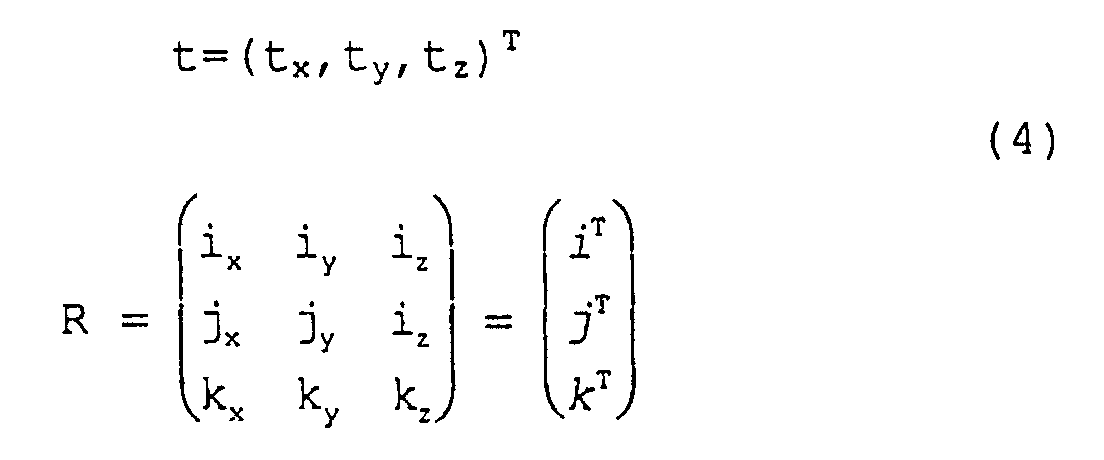
- the situation of the target 1 can be represented by a rotation R and a translation t in accordance with the following matrices (4), which pass from the reference of the video camera 4, defined above, to a fixed reference, linked to the target 1: where t x , t y and t z are translation coordinates expressed in the axes i, j and k of the coordinate system of camera 4 and i , j and k are the directing vectors of the coordinate system of camera 4 expressed in the coordinate system of target 1.
- the plane ⁇ is chosen such that the origin O of the coordinate system of the test pattern 1 belongs to it, which implies that the focus F is distant from the plane ⁇ by the quantity t z .
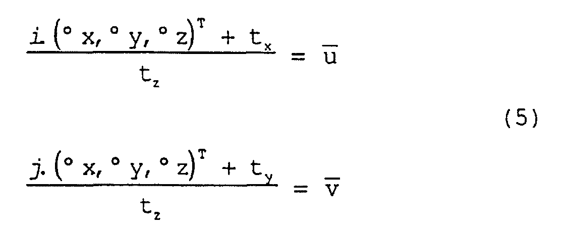
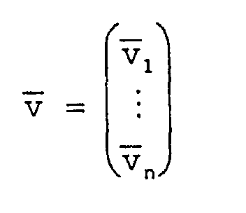
- the final estimate of the localization parameters of test pattern 1, that is to say values of coefficients of the matrices R and t which give the position and the orientation of the reference mark of test pattern 1, is obtained by minimizing the quadratic error between the coordinates u and v measured on the points Pp of image 10 and the coordinates û and v and ° Pp projections, calculated by the previous formulas (9), ° P points.
- test pattern 1 acts by iterations, by moving each time the points ° P according to the positions of their projections ° P p on the image 10, until these projections have sufficiently converged towards the centers Pp of the traces 13.
- the localization of the test pattern 1 being known in a fixed coordinate system, it is then possible to know that of the video camera 4 in this same coordinate system by calculating the reverse transformation.
- the application of the principle of localization of the position of a camera used in the invention exploits the possibility of calibrating the position respective of several cameras mounted on a head mobile. This is to control the geometry of the vehicles (wheel parallelism) in a automotive control (see Fig. 6).
- the device consists to equip the wheels 56 of the vehicle to be checked 55 with 54 plates bearing retro-reflective marks 57, two cameras 51 and 52 then being placed on the side and other and in front of the vehicle.
- a technique known three-dimensional location of the plates appearing in the field of each camera allows to accurately determine the angular position of each wheel 56 relative to the camera 51 or 52. It is therefore possible to determine whether the two wheels 56 of a same side of the vehicle are parallel because the plates control are then in the field of the same camera 51 or 52 which provides the benchmark.
- a first device would be to rigidly fix the two cameras 51 and 52 to a transverse support and to calibrate the position of cameras 51 and 52 by implementing the technique of this patent. It would be necessary to have a test pattern bearing marks in the field of two cameras to know the position of each camera in the target of this target, and by difference, the position transformation between the two cameras 51 and 52.
- This geometry control device for vehicles would involve rigid mechanical realization and stable, which will be heavy to install and cumbersome.
- Camera 52 is equipped with a plate 59 bearing marks 58 oriented towards the camera 51, and a third camera 53 is integral with the support of the camera 51 and oriented towards the camera 52.
- the implementation of the technique of this patent analyzing the images of plate 59 obtained by the camera 53 allows to know permanently (at each parallelism measurement) the actual position of the camera 53 compared to plate 59.
- the two devices: camera 51 associated with camera 53 on the one hand and camera 52 and its plate 59 bearing marks 58 on the other hand, are previously calibrated in the factory using a measurement bench equipped with another camera and a test pattern associated to know precisely their parameters fixed geometries.
- Such a process could be generalized to any system comprising several observation cameras of a same object, or neighboring portions of the same object or of the same space, and whose views must be correlated with each other to juxtapose them and reconstruct the object or deduce characteristics of the space observed.
Landscapes
- Engineering & Computer Science (AREA)
- Physics & Mathematics (AREA)
- General Physics & Mathematics (AREA)
- Computer Vision & Pattern Recognition (AREA)
- Theoretical Computer Science (AREA)
- Multimedia (AREA)
- Radar, Positioning & Navigation (AREA)
- Remote Sensing (AREA)
- Length Measuring Devices By Optical Means (AREA)
- Navigation (AREA)
- Position Fixing By Use Of Radio Waves (AREA)
Abstract
Description
- la figure 1 est une vue schématique et générale des éléments qui interviennent dans la localisation de la position et de l'orientation initiales de la caméra à l'aide d'une mire ;
- la figure 2 illustre la technique de recherche des traces des marques de la mire sur l'image prise par la caméra ;
- les figures 3 et 4 illustrent une modélisation d'une trace de marque sur l'image ;
- la figure 5 est une représentation géométrique d'explication du procédé de localisation et d'orientation de la caméra ;
- et la figure 6 illustre une façon de mettre en oeuvre l'invention.




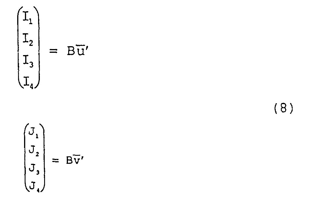
- calcul des normes nI = ∥(I1,I2,I3)T∥ et nJ = ∥(J1,J2,J3)T∥ ;
- calcul de la norme moyenne n=(nI+nJ)/2 ;
- calcul de i=(I1,I2,I3)T/nI et de j=(J1,J2,J3)T/nJ ;
- calcul de k par le produit vectoriel des vecteurs i et j ;
- calcul de la composante tz=1/n ;
- calcul de tx=I4tz et de ty=J4tz.


Claims (6)
- Procédé d'étalonnage, par rapport à une seconde caméra (52), de la position et de l'orientation d'origine d'une première caméra (51), les caméras étant disposées sur des supports indépendants et mobiles (60) dans un environnement, caractérisé en ce qu'il consiste à munir la première caméra d'une caméra d'étalonnage (53) et la seconde caméra d'une mire (58) à une position et une orientation connues ; à prendre une image de la mire par la caméra d'étalonnage ; et à analyser l'image de la mire par un système de traitement en relevant des positions de traces (Pp) de marques caractéristiques (3) de la mire sur l'image et en déduisant des directions et des éloignements entre les marques caractéristiques et la caméra d'étalonnage, puis une position et une orientation de la caméra d'étalonnage (53) par rapport à la mire, puis de la première caméra (51) par rapport à la seconde caméra (52).
- Procédé selon la revendication 1, caractérisé en ce que la mire (58) comprend au moins trois marques dans le champ de la caméra à étalonner (51), et avantageusement plus de trois marques non coplanaires.
- Procédé selon l'une quelconque des revendications 1 ou 2, caractérisé en ce que la position et l'orientation de la caméra d'étalonnage (53) par rapport à la mire (58) sont déduites sous forme d'une position (t) et d'une orientation (R) de la caméra à étalonner (51) par rapport à un repère lié à la mire.
- Procédé selon l'une quelconque des revendications 1 à 3, caractérisé en ce qu'il consiste à déduire les directions et les éloignements entre les marques caractéristiques et la caméra d'étalonnage (53) en effectuant une rétro-projection des centres des traces des marques caractéristiques (3) de la mire d'abord sur un plan (Π) passant par l'origine du repère de la mire et parallèle au plan de l'image le long de lignes convergeant vers un foyer unique (F), puis dans l'espace, perpendiculairement audit plan parallèle pour obtenir des points de rétro-projection (°P), et ensuite, de façon itérative, une projection des points de rétro-projection (°P) sur le plan de l'image (10) le long de lignes convergeant vers le foyer (F) pour obtenir des points de projection (°Pp), et une correction de position des points de rétro-projection pour minimiser un critère d'estimation d'erreur entre des coordonnées des centres des traces (Pp) des marques caractéristiques (3) et des points de projection (°Pp).
- Procédé conforme à la revendication 1, caractérisé en ce qu'il est appliqué à l'observation du contenu d'un même espace à partir de vues partielles de ce contenu fournies par la première et seconde caméras (51, 52).
- Procédé selon la revendication 5, caractérisé en ce qu'il comporte un calcul d'une relation géométrique entre des portions d'un objet (55) apparaissant respectivement sur les vues partielles.
Applications Claiming Priority (3)
| Application Number | Priority Date | Filing Date | Title |
|---|---|---|---|
| FR9713375 | 1997-10-24 | ||
| FR9713375A FR2770317B1 (fr) | 1997-10-24 | 1997-10-24 | Procede d'etalonnage de la position et de l'orientation d'origine d'une ou plusieurs cameras mobiles et son application a la mesure de position tridimentionnelle d'objets fixes |
| PCT/FR1998/002270 WO1999022281A1 (fr) | 1997-10-24 | 1998-10-23 | Procede d'etalonnage de la position et de l'orientation d'origine d'une ou plusieurs cameras mobiles |
Publications (2)
| Publication Number | Publication Date |
|---|---|
| EP0948760A1 EP0948760A1 (fr) | 1999-10-13 |
| EP0948760B1 true EP0948760B1 (fr) | 2002-07-31 |
Family
ID=9512627
Family Applications (1)
| Application Number | Title | Priority Date | Filing Date |
|---|---|---|---|
| EP98951539A Expired - Lifetime EP0948760B1 (fr) | 1997-10-24 | 1998-10-23 | Procede d'etalonnage de la position et de l'orientation d'origine d'une ou plusieurs cameras mobiles |
Country Status (8)
| Country | Link |
|---|---|
| US (1) | US6594600B1 (fr) |
| EP (1) | EP0948760B1 (fr) |
| JP (1) | JP4201059B2 (fr) |
| CA (1) | CA2275957C (fr) |
| DE (1) | DE69806894T2 (fr) |
| ES (1) | ES2181283T3 (fr) |
| FR (1) | FR2770317B1 (fr) |
| WO (1) | WO1999022281A1 (fr) |
Cited By (6)
| Publication number | Priority date | Publication date | Assignee | Title |
|---|---|---|---|---|
| US6731382B2 (en) | 2000-08-14 | 2004-05-04 | Snap-On Technologies, Inc. | Self-calibrating 3D machine measuring system useful in motor vehicle wheel alignment |
| US6839972B2 (en) | 2001-06-15 | 2005-01-11 | Snap-On Incorporated | Self-calibrating position determination system |
| US6931340B2 (en) * | 2000-05-22 | 2005-08-16 | Snap-On Incorporated | Self-calibrating, multi-camera machine vision measuring system |
| US6959253B2 (en) | 2000-03-23 | 2005-10-25 | Snap-On Incorporated | Self-calibrating, multi-camera machine vision measuring system |
| US7062861B2 (en) | 2001-06-28 | 2006-06-20 | Snap-On Incorporated | Self-calibrating position determination system and user interface |
| US11205283B2 (en) | 2017-02-16 | 2021-12-21 | Qualcomm Incorporated | Camera auto-calibration with gyroscope |
Families Citing this family (111)
| Publication number | Priority date | Publication date | Assignee | Title |
|---|---|---|---|---|
| US7065462B2 (en) * | 1998-07-24 | 2006-06-20 | Merilab, Inc. | Vehicle wheel alignment by rotating vision sensor |
| US6169759B1 (en) | 1999-03-22 | 2001-01-02 | Golden Bridge Technology | Common packet channel |
| NO313113B1 (no) * | 1999-07-13 | 2002-08-12 | Metronor Asa | System for scanning av store objekters geometri |
| FR2801123B1 (fr) * | 1999-11-12 | 2002-04-05 | Bertrand Aube | Procede de creation automatique de maquette numerique a partir de couples d'images stereoscopiques |
| US6542840B2 (en) | 2000-01-27 | 2003-04-01 | Matsushita Electric Industrial Co., Ltd. | Calibration system, target apparatus and calibration method |
| JP3387911B2 (ja) * | 2000-01-27 | 2003-03-17 | 松下電器産業株式会社 | キャリブレーションシステムおよびキャリブレーション方法 |
| US7151562B1 (en) * | 2000-08-03 | 2006-12-19 | Koninklijke Philips Electronics N.V. | Method and apparatus for external calibration of a camera via a graphical user interface |
| US6891960B2 (en) * | 2000-08-12 | 2005-05-10 | Facet Technology | System for road sign sheeting classification |
| US6963666B2 (en) * | 2000-09-12 | 2005-11-08 | Pentax Corporation | Matching device |
| SE0003373L (sv) * | 2000-09-20 | 2002-01-29 | Jan G Faeger | Metod och anordning för att producera information om en omgivning och användning av anordningen |
| US6997387B1 (en) * | 2001-03-28 | 2006-02-14 | The Code Corporation | Apparatus and method for calibration of projected target point within an image |
| JP3759429B2 (ja) * | 2001-05-23 | 2006-03-22 | 株式会社東芝 | 障害物検出装置及びその方法 |
| JP4892792B2 (ja) * | 2001-07-04 | 2012-03-07 | コニカミノルタホールディングス株式会社 | 測定装置及び測定方法 |
| US7423666B2 (en) * | 2001-05-25 | 2008-09-09 | Minolta Co., Ltd. | Image pickup system employing a three-dimensional reference object |
| JP4892793B2 (ja) * | 2001-07-04 | 2012-03-07 | コニカミノルタホールディングス株式会社 | 測定装置及び測定方法 |
| JP2003050107A (ja) * | 2001-08-07 | 2003-02-21 | Matsushita Electric Ind Co Ltd | カメラ校正装置 |
| EP1472052A2 (fr) * | 2002-01-31 | 2004-11-03 | Braintech Canada, Inc. | Procede et appareil pour robotique guidee par vision 3d au moyen d'une camera unique |
| JP2003258742A (ja) * | 2002-02-27 | 2003-09-12 | Tasada Kosakusho:Kk | 通信障害物調査装置 |
| US7302093B2 (en) * | 2002-03-26 | 2007-11-27 | Hunter Engineering Company | Color vision vehicle wheel alignment system |
| FR2838198B1 (fr) * | 2002-04-05 | 2004-06-25 | Acticm | Repere dispose dans un environnement a mesurer et systeme de mesure comprenant ce repere |
| EP1383098B1 (fr) * | 2002-07-09 | 2006-05-17 | Accenture Global Services GmbH | Dispositif de détection automatique de panneaux de signalisation routière |
| KR100493159B1 (ko) * | 2002-10-01 | 2005-06-02 | 삼성전자주식회사 | 이동체의 효율적 자기 위치 인식을 위한 랜드마크 및 이를이용한 자기 위치 인식 장치 및 방법 |
| DE10246066B4 (de) * | 2002-10-02 | 2007-11-22 | Robert Bosch Gmbh | Verfahren und Vorrichtung zur Kalibrierung eines Bildsensorsystems in einem Kraftfahrzeug |
| US7602413B2 (en) * | 2002-10-18 | 2009-10-13 | Sony Corporation | Information processing system and method, information processing apparatus, image-capturing device and method, recording medium, and program |
| US6762790B1 (en) * | 2002-12-20 | 2004-07-13 | Bendix Commercial Vehicle Systems Llc | Universal camera bracket that allows 180 degree of pitch adjustment |
| TWI360702B (en) * | 2003-03-07 | 2012-03-21 | Semiconductor Energy Lab | Liquid crystal display device and method for manuf |
| US7164472B2 (en) * | 2003-10-09 | 2007-01-16 | Hunter Engineering Company | Common reference target machine vision wheel alignment system |
| DE102004010197B4 (de) * | 2004-03-02 | 2015-04-16 | Sick Ag | Verfahren zur Funktionskontrolle einer Positionsermittlungs- oder Umgebungserfassungseinrichtung eines Fahrzeugs oder zur Kontrolle einer digitalen Karte |
| EP1759173A4 (fr) * | 2004-06-02 | 2012-02-22 | Rockwell Collins Control Technologies Inc | Système et méthode de navigation inertielle augmentée d"images (image-augmented inertial navigation system, iains) |
| EP1766580A2 (fr) * | 2004-07-14 | 2007-03-28 | Braintech Canada, Inc. | Procede et systeme de visionique |
| US8207964B1 (en) | 2008-02-22 | 2012-06-26 | Meadow William D | Methods and apparatus for generating three-dimensional image data models |
| US7929800B2 (en) | 2007-02-06 | 2011-04-19 | Meadow William D | Methods and apparatus for generating a continuum of image data |
| JP4224449B2 (ja) | 2004-11-30 | 2009-02-12 | 本田技研工業株式会社 | 画像抽出装置 |
| JP4032052B2 (ja) | 2004-11-30 | 2008-01-16 | 本田技研工業株式会社 | 位置検出装置及びその補正方法 |
| JP4461091B2 (ja) | 2004-11-30 | 2010-05-12 | 本田技研工業株式会社 | 位置検出装置及びその補正方法 |
| US7590263B2 (en) | 2004-11-30 | 2009-09-15 | Honda Motor Co., Ltd. | Vehicle vicinity monitoring apparatus |
| US7599521B2 (en) | 2004-11-30 | 2009-10-06 | Honda Motor Co., Ltd. | Vehicle vicinity monitoring apparatus |
| JP5127128B2 (ja) * | 2004-12-21 | 2013-01-23 | 韓國電子通信研究院 | カメラの位置及び姿勢情報補正方法及びその装置 |
| DE102005007536A1 (de) | 2005-02-17 | 2007-01-04 | Isra Vision Systems Ag | Verfahren zur Kalibrierung eines Messsystems |
| US7356425B2 (en) * | 2005-03-14 | 2008-04-08 | Ge Security, Inc. | Method and system for camera autocalibration |
| US8838374B2 (en) * | 2005-07-05 | 2014-09-16 | Mi-Jack Products, Inc. | Automatic correction of past position errors for location and inventory tracking |
| WO2007041696A2 (fr) * | 2005-10-04 | 2007-04-12 | Alexander Eugene J | Systeme et procede d'etalonnage d'un ensemble de dispositifs d'imagerie et calcul de coordonnees en 3d de caracteristiques detectees dans un systeme de coordonnees de laboratoire |
| EP1946567A4 (fr) * | 2005-10-04 | 2009-02-18 | Eugene J Alexander | Dispositif permettant de generer des modeles de surface en trois dimensions d'objets en mouvement |
| WO2007048425A1 (fr) * | 2005-10-26 | 2007-05-03 | Trimble Jena Gmbh | Procédé d'enquête et instrument d'enquête |
| EP1960941A4 (fr) * | 2005-11-10 | 2012-12-26 | Motion Analysis Corp | Dispositif et procede d'etalonnage d'un dispositif de traitement d'image pour generer des modeles a surface tridimensionnelle d'objets en mouvement |
| JP4684147B2 (ja) * | 2006-03-28 | 2011-05-18 | 任天堂株式会社 | 傾き算出装置、傾き算出プログラム、ゲーム装置およびゲームプログラム |
| WO2007125377A1 (fr) * | 2006-04-28 | 2007-11-08 | Nokia Corporation | Étalonnage |
| US20070276539A1 (en) * | 2006-05-25 | 2007-11-29 | Babak Habibi | System and method of robotically engaging an object |
| JP4820221B2 (ja) * | 2006-06-29 | 2011-11-24 | 日立オートモティブシステムズ株式会社 | 車載カメラのキャリブレーション装置およびプログラム |
| WO2008036354A1 (fr) * | 2006-09-19 | 2008-03-27 | Braintech Canada, Inc. | Système et procédé de détermination de la pose d'un objet |
| US7839431B2 (en) * | 2006-10-19 | 2010-11-23 | Robert Bosch Gmbh | Image processing system and method for improving repeatability |
| JP2008187564A (ja) * | 2007-01-31 | 2008-08-14 | Sanyo Electric Co Ltd | カメラ校正装置及び方法並びに車両 |
| JP4969279B2 (ja) | 2007-03-22 | 2012-07-04 | 本田技研工業株式会社 | 位置検出方法および位置検出装置 |
| US7558688B2 (en) * | 2007-04-20 | 2009-07-07 | Northrop Grumman Corporation | Angle calibration of long baseline antennas |
| DE102007030378A1 (de) * | 2007-06-29 | 2009-01-02 | Spatial View Gmbh Dresden | System zur Bestimmung der Lage eines Kamerasystems |
| US7957583B2 (en) * | 2007-08-02 | 2011-06-07 | Roboticvisiontech Llc | System and method of three-dimensional pose estimation |
| TW200937348A (en) * | 2008-02-19 | 2009-09-01 | Univ Nat Chiao Tung | Calibration method for image capturing device |
| US8320613B2 (en) * | 2008-06-04 | 2012-11-27 | Lockheed Martin Corporation | Detecting and tracking targets in images based on estimated target geometry |
| US9279882B2 (en) * | 2008-09-19 | 2016-03-08 | Caterpillar Inc. | Machine sensor calibration system |
| US20100076710A1 (en) * | 2008-09-19 | 2010-03-25 | Caterpillar Inc. | Machine sensor calibration system |
| US8918302B2 (en) * | 2008-09-19 | 2014-12-23 | Caterpillar Inc. | Machine sensor calibration system |
| US8180487B1 (en) | 2008-09-30 | 2012-05-15 | Western Digital Technologies, Inc. | Calibrated vision based robotic system |
| US8559699B2 (en) * | 2008-10-10 | 2013-10-15 | Roboticvisiontech Llc | Methods and apparatus to facilitate operations in image based systems |
| US8138938B2 (en) * | 2008-10-28 | 2012-03-20 | The Boeing Company | Hand-held positioning interface for spatial query |
| US8135208B1 (en) | 2009-01-15 | 2012-03-13 | Western Digital Technologies, Inc. | Calibrated vision based robotic system utilizing upward and downward looking cameras |
| US8698875B2 (en) * | 2009-02-20 | 2014-04-15 | Google Inc. | Estimation of panoramic camera orientation relative to a vehicle coordinate frame |
| JP4690476B2 (ja) * | 2009-03-31 | 2011-06-01 | アイシン精機株式会社 | 車載カメラの校正装置 |
| US8855929B2 (en) * | 2010-01-18 | 2014-10-07 | Qualcomm Incorporated | Using object to align and calibrate inertial navigation system |
| KR101001842B1 (ko) * | 2010-01-28 | 2010-12-17 | 팅크웨어(주) | 차량용 내비게이션 및 내비게이션 시스템의 블랙박스 정상 위치 유도 방법 |
| FR2958196B1 (fr) * | 2010-04-02 | 2012-06-15 | Dcns | Procede et systeme d'aide au positionnement d'une piece sur un element de structure. |
| US9229089B2 (en) | 2010-06-10 | 2016-01-05 | Qualcomm Incorporated | Acquisition of navigation assistance information for a mobile station |
| FR2962581B1 (fr) | 2010-07-06 | 2013-07-05 | Imajing | Methode de calibration de l'orientation d'une camera video embarquee |
| CN101975588B (zh) * | 2010-08-20 | 2012-07-11 | 北京航空航天大学 | 一种多传感器视觉测量系统的刚性杆全局校准方法及装置 |
| US8593535B2 (en) | 2010-09-10 | 2013-11-26 | Apple Inc. | Relative positioning of devices based on captured images of tags |
| US8611594B2 (en) | 2010-09-10 | 2013-12-17 | Apple Inc. | Dynamic display of virtual content on several devices using reference tags |
| US9160980B2 (en) * | 2011-01-11 | 2015-10-13 | Qualcomm Incorporated | Camera-based inertial sensor alignment for PND |
| US8775064B2 (en) * | 2011-05-10 | 2014-07-08 | GM Global Technology Operations LLC | Sensor alignment process and tools for active safety vehicle applications |
| WO2013053103A1 (fr) * | 2011-10-11 | 2013-04-18 | Ji Ying | Procédé de détermination des paramètres d'étalonnage directionnel et de la direction d'actionnement d'un instrument chirurgical et outil d'étalonnage associé |
| US8853634B2 (en) * | 2012-03-12 | 2014-10-07 | The Boeing Company | Resin detection system |
| US8798357B2 (en) * | 2012-07-09 | 2014-08-05 | Microsoft Corporation | Image-based localization |
| US9420275B2 (en) | 2012-11-01 | 2016-08-16 | Hexagon Technology Center Gmbh | Visual positioning system that utilizes images of a working environment to determine position |
| US9441974B2 (en) | 2013-03-15 | 2016-09-13 | Novatel Inc. | System and method for calculating lever arm values photogrammetrically |
| US9955142B2 (en) * | 2013-07-05 | 2018-04-24 | Mediatek Inc. | On-line stereo camera calibration device and method for generating stereo camera parameters |
| JP6375660B2 (ja) * | 2014-01-21 | 2018-08-22 | セイコーエプソン株式会社 | 位置検出装置、プロジェクター、位置検出システム、及び、位置検出装置の制御方法 |
| GB201411028D0 (en) * | 2014-06-20 | 2014-08-06 | Inst Of Technology Blanchardstown | Mobile road sign reflectometer |
| DE102014213175A1 (de) * | 2014-07-07 | 2016-01-07 | Conti Temic Microelectronic Gmbh | Vorrichtung zur entfernungsmessung, fahrzeug und verfahren |
| US9569693B2 (en) * | 2014-12-31 | 2017-02-14 | Here Global B.V. | Method and apparatus for object identification and location correlation based on received images |
| CN104637300B (zh) * | 2015-02-06 | 2017-01-04 | 南京理工大学 | 公路交通标志牌信息化普查分析与展示系统 |
| DE112016001137B4 (de) * | 2015-03-11 | 2024-01-18 | Nalux Co., Ltd. | Mit Abschnitt zur Positionsbestimmung versehenes Element und Messverfahren |
| CN107850901B (zh) | 2015-05-23 | 2021-04-16 | 深圳市大疆创新科技有限公司 | 使用惯性传感器和图像传感器的传感器融合 |
| CN107850436B (zh) * | 2015-05-23 | 2021-03-05 | 深圳市大疆创新科技有限公司 | 使用惯性传感器和图像传感器的传感器融合 |
| US10088318B2 (en) * | 2015-08-27 | 2018-10-02 | Qualcomm Incorporated | Cradle rotation insensitive inertial navigation |
| JP6639181B2 (ja) * | 2015-10-13 | 2020-02-05 | キヤノン株式会社 | 撮像装置、生産システム、撮像方法、プログラム及び記録媒体 |
| DE102015223471A1 (de) * | 2015-11-26 | 2017-06-01 | Bayerische Motoren Werke Aktiengesellschaft | System zum Einparken eines Fahrzeugs |
| DE102017211038A1 (de) * | 2017-06-29 | 2019-01-03 | Robert Bosch Gmbh | Verfahren zum Einstellen einer Kamera |
| WO2019023416A1 (fr) * | 2017-07-27 | 2019-01-31 | Westinghouse Electric Company Llc | Procédé de localisation d'un véhicule télécommandé dans un espace de travail et système d'inspection à distance utilisant un tel procédé |
| US11250589B2 (en) * | 2017-08-25 | 2022-02-15 | Chris Hsinlai Liu | General monocular machine vision system and method for identifying locations of target elements |
| CN107907711A (zh) * | 2017-10-31 | 2018-04-13 | 北京航天计量测试技术研究所 | 一种小型化加速度计测试设备 |
| CN109389650B (zh) * | 2018-09-30 | 2021-01-12 | 京东方科技集团股份有限公司 | 一种车载相机的标定方法、装置、车辆和存储介质 |
| JP7529266B2 (ja) * | 2018-12-27 | 2024-08-06 | 日本電気通信システム株式会社 | 物品位置管理装置、物品位置管理システム、物品位置管理方法及びプログラム |
| EP3946825A1 (fr) * | 2019-03-25 | 2022-02-09 | ABB Schweiz AG | Procédé et agencement de commande pour déterminer une relation entre un système de coordonnées d'un robot et un système de coordonnées d'un appareil mobile |
| JP7127592B2 (ja) * | 2019-03-27 | 2022-08-30 | オムロン株式会社 | 報知システム |
| CN110174105B (zh) * | 2019-06-14 | 2022-02-11 | 西南科技大学 | 一种复杂环境下智能体自主导航算法及系统 |
| CN110658918B (zh) * | 2019-09-25 | 2023-12-12 | 京东方科技集团股份有限公司 | 用于视频眼镜的眼球追踪相机的定位方法、设备及介质 |
| CN110673155A (zh) * | 2019-09-30 | 2020-01-10 | 国网湖南省电力有限公司 | 一种输电线路结构物的探测装置、探测系统及其方法 |
| US10846880B1 (en) | 2020-01-03 | 2020-11-24 | Altec Industries, Inc. | Camera embedded joystick |
| EP4256461A1 (fr) * | 2020-12-04 | 2023-10-11 | Robert Bosch GmbH | Procédé de détermination d'une pose de caméra dans un système à caméras multiples, programme informatique, support lisible par machine et unité de commande |
| US11870973B2 (en) * | 2021-07-27 | 2024-01-09 | Deere & Company | Camera calibration tool |
| CN116038719B (zh) * | 2023-04-03 | 2023-07-18 | 广东工业大学 | 一种机械臂末端位姿跟踪测量方法、装置及设备 |
| CN117134117B (zh) * | 2023-09-12 | 2024-07-02 | 佛山市粤海信通讯有限公司 | 一种天线辐射方向校准器 |
| US12400367B2 (en) * | 2023-12-14 | 2025-08-26 | Industrial Technology Research Institute | Camera calibration method based on vehicle localization |
Family Cites Families (15)
| Publication number | Priority date | Publication date | Assignee | Title |
|---|---|---|---|---|
| US4396942A (en) * | 1979-04-19 | 1983-08-02 | Jackson Gates | Video surveys |
| US4753569A (en) * | 1982-12-28 | 1988-06-28 | Diffracto, Ltd. | Robot calibration |
| US4831561A (en) * | 1986-06-19 | 1989-05-16 | Tokico Ltd. | Work position error detecting apparatus |
| US4831549A (en) * | 1987-07-28 | 1989-05-16 | Brigham Young University | Device and method for correction of robot inaccuracy |
| US4893183A (en) * | 1988-08-11 | 1990-01-09 | Carnegie-Mellon University | Robotic vision system |
| DE3941144C2 (de) * | 1989-12-13 | 1994-01-13 | Zeiss Carl Fa | Koordinatenmeßgerät zur berührungslosen Vermessung eines Objekts |
| US5073819A (en) * | 1990-04-05 | 1991-12-17 | Computer Scaled Video Surveys, Inc. | Computer assisted video surveying and method thereof |
| IT1262820B (it) * | 1993-02-16 | 1996-07-04 | Corghi Spa | Sistema per il rilevamento degli angoli caratteristici dell'assetto delle ruote di un autotelaio e mezzi di misura relativi. |
| FR2706345B1 (fr) * | 1993-06-11 | 1995-09-22 | Bertin & Cie | Procédé et dispositif de repérage dans l'espace d'un objet mobile tel qu'un capteur ou un outil porté par un robot. |
| JP3522317B2 (ja) * | 1993-12-27 | 2004-04-26 | 富士重工業株式会社 | 車輌用走行案内装置 |
| FR2749419B1 (fr) * | 1996-05-31 | 1998-08-28 | Sagem | Procede et dispositif d'identification et de localisation d'objets fixes le long d'un trajet |
| FR2760277B1 (fr) * | 1997-02-28 | 1999-03-26 | Commissariat Energie Atomique | Procede et dispositif de localisation d'un objet dans l'espace |
| US6310644B1 (en) * | 1997-03-26 | 2001-10-30 | 3Dm Devices Inc. | Camera theodolite system |
| GB9803364D0 (en) * | 1998-02-18 | 1998-04-15 | Armstrong Healthcare Ltd | Improvements in or relating to a method of an apparatus for registering a robot |
| EP1309832B1 (fr) * | 2000-08-14 | 2008-10-22 | Snap-on Incorporated | Système de mesure 3D à auto-etalonnage pour aligner les roues d'un véhicule |
-
1997
- 1997-10-24 FR FR9713375A patent/FR2770317B1/fr not_active Expired - Fee Related
-
1998
- 1998-10-23 EP EP98951539A patent/EP0948760B1/fr not_active Expired - Lifetime
- 1998-10-23 DE DE69806894T patent/DE69806894T2/de not_active Expired - Lifetime
- 1998-10-23 JP JP52338999A patent/JP4201059B2/ja not_active Expired - Fee Related
- 1998-10-23 US US09/331,112 patent/US6594600B1/en not_active Expired - Fee Related
- 1998-10-23 ES ES98951539T patent/ES2181283T3/es not_active Expired - Lifetime
- 1998-10-23 CA CA2275957A patent/CA2275957C/fr not_active Expired - Fee Related
- 1998-10-23 WO PCT/FR1998/002270 patent/WO1999022281A1/fr not_active Ceased
Non-Patent Citations (4)
| Title |
|---|
| ABIDI M. A., CHANDRA T.: "POSE ESTIMATION FOR CAMERA CALIBRATION AND LANDMARK TRACKING.", PROCEEDINGS OF THE INTERNATIONAL CONFERENCE ON ROBOTICS AND AUTOMATION. CINCINNATI, MAY 13 - 18, 1990., LOS ALAMITOS, IEEE COMP. SOC. PRESS., US, vol. -, 13 May 1990 (1990-05-13), US, pages 420 - 426., XP000139944, ISBN: 978-0-8186-9061-7, DOI: 10.1109/ROBOT.1990.126013 * |
| HE G., NOVAK K., FENG W.: "STEREO CAMERA SYSTEM CALIBRATION WITH RELATIVE ORIENTATION CONSTRAINTS.", OPTOMECHATRONIC MICRO/NANO DEVICES AND COMPONENTS III : 8 - 10 OCTOBER 2007, LAUSANNE, SWITZERLAND, SPIE, BELLINGHAM, WASH., vol. 1820., 15 November 1992 (1992-11-15), Bellingham, Wash., pages 02 - 08., XP002050119, ISBN: 978-1-62841-730-2, DOI: 10.1117/12.141367 * |
| OBERKAMPF D., DEMENTHON D.F., DAVIS L.S.: "ITERATIVE POSE ESTIMATION USING COPLANAR FEATURE POINTS.", COMPUTER VISION AND IMAGE UNDERSTANDING., ACADEMIC PRESS., US, vol. 63., no. 03., 1 May 1996 (1996-05-01), US, pages 495 - 511., XP000597554, ISSN: 1077-3142, DOI: 10.1006/cviu.1996.0037 * |
| RADU HORAUD, ET AL.: "AN ANALYTIC SOLUTION FOR THE PERSPECTIVE 4-POINT PROBLEM.", COMPUTER VISION GRAPHICS AND IMAGE PROCESSING., ACADEMIC PRESS, DULUTH, MA., US, vol. 47., no. 01., 1 July 1989 (1989-07-01), US, pages 33 - 44., XP000086842, DOI: 10.1016/0734-189X(89)90052-2 * |
Cited By (6)
| Publication number | Priority date | Publication date | Assignee | Title |
|---|---|---|---|---|
| US6959253B2 (en) | 2000-03-23 | 2005-10-25 | Snap-On Incorporated | Self-calibrating, multi-camera machine vision measuring system |
| US6931340B2 (en) * | 2000-05-22 | 2005-08-16 | Snap-On Incorporated | Self-calibrating, multi-camera machine vision measuring system |
| US6731382B2 (en) | 2000-08-14 | 2004-05-04 | Snap-On Technologies, Inc. | Self-calibrating 3D machine measuring system useful in motor vehicle wheel alignment |
| US6839972B2 (en) | 2001-06-15 | 2005-01-11 | Snap-On Incorporated | Self-calibrating position determination system |
| US7062861B2 (en) | 2001-06-28 | 2006-06-20 | Snap-On Incorporated | Self-calibrating position determination system and user interface |
| US11205283B2 (en) | 2017-02-16 | 2021-12-21 | Qualcomm Incorporated | Camera auto-calibration with gyroscope |
Also Published As
| Publication number | Publication date |
|---|---|
| JP4201059B2 (ja) | 2008-12-24 |
| WO1999022281A1 (fr) | 1999-05-06 |
| FR2770317B1 (fr) | 2000-12-08 |
| ES2181283T3 (es) | 2003-02-16 |
| CA2275957C (fr) | 2011-12-20 |
| JP2001506369A (ja) | 2001-05-15 |
| US6594600B1 (en) | 2003-07-15 |
| EP0948760A1 (fr) | 1999-10-13 |
| FR2770317A1 (fr) | 1999-04-30 |
| DE69806894D1 (de) | 2002-09-05 |
| DE69806894T2 (de) | 2003-03-13 |
| CA2275957A1 (fr) | 1999-05-06 |
Similar Documents
| Publication | Publication Date | Title |
|---|---|---|
| CA2275957C (fr) | Procede d'etalonnage de la position et de l'orientation d'origine d'une ou plusieurs cameras mobiles | |
| EP0863413B1 (fr) | Procédé et dispositif de localisation d'un objet dans l'espace | |
| EP3680615B1 (fr) | Methode de determination d'un rayon de protection d'un systeme de navigation base sur la vision | |
| EP2884226B1 (fr) | Procédé de calibration angulaire de la position d'une caméra video embarquée dans un véhicule automobile | |
| EP2923330B1 (fr) | Procede de reconstruction 3d et de mosaïquage 3d panoramique d'une scene | |
| US11721038B2 (en) | Camera orientation estimation | |
| FR2836215A1 (fr) | Systeme et procede de modelisation et de restitution tridimensionnelle d'un objet | |
| EP2502202B1 (fr) | Procede d'estimation du mouvement d'un instrument d'observation à defilement survolant un corps celeste | |
| EP0897163B1 (fr) | Procédé de production de données cartographiques par stéréovision | |
| EP2405399A1 (fr) | Méthode de calibration de l'orientation d'une caméra vidéo embarquée | |
| FR2719920A1 (fr) | Procédé et dispositif destinés à soutenir la navigation inertielle d'un missile se dirigeant de façon autonome sur une cible éloignée. | |
| EP0141706A2 (fr) | Procédé et appareillage pour déterminer l'attitude d'un objet dans l'espace par rapport à un poste d'observation | |
| FR2729236A1 (fr) | Guidage de robot par eclairage actif | |
| FR3053554A1 (fr) | Procede de calibration rapide d'une camera de vehicule automobile | |
| EP4526843B1 (fr) | Procédé et dispositif de détermination de pose absolue d'une caméra embarquée dans un engin aérien ou spatial | |
| WO2014180797A1 (fr) | Procede de commande d'une interface graphique pour afficher des images d'un objet tridimensionnel | |
| EP4212825B1 (fr) | Procédé d alignement d'une caméra sur une route | |
| EP3018625B1 (fr) | Procédé de calibration d'un système de visée | |
| FR3109629A1 (fr) | Procédé de calage géométrique d’images optiques | |
| FR3106904A1 (fr) | Procédé de calibration des caractéristiques extrinsèques d’un Lidar | |
| WO2021105289A1 (fr) | Système et procédé d'harmonisation automatique de position et/ou d'orientation entre un équipement embarqué sur un porteur mobile et un référentiel dudit porteur mobile | |
| FR3098929A1 (fr) | Procédé de détermination de paramètres d'étalonnage extrinseques d'un système de mesure | |
| EP3865816A1 (fr) | Méthodes et systèmes pour mesurer à distance l'orientation angulaire d'un objet | |
| FR3138951A1 (fr) | Système et procédé d’aide à la navigation d’un système mobile au moyen d’un modèle de prédiction de traversabilité d’un terrain par le système mobile | |
| WO2018229358A1 (fr) | Procédé et dispositif de construction d'une image tridimensionnelle |
Legal Events
| Date | Code | Title | Description |
|---|---|---|---|
| PUAI | Public reference made under article 153(3) epc to a published international application that has entered the european phase |
Free format text: ORIGINAL CODE: 0009012 |
|
| 17P | Request for examination filed |
Effective date: 19990526 |
|
| AK | Designated contracting states |
Kind code of ref document: A1 Designated state(s): DE ES FR GB IT SE |
|
| 17Q | First examination report despatched |
Effective date: 20010131 |
|
| GRAG | Despatch of communication of intention to grant |
Free format text: ORIGINAL CODE: EPIDOS AGRA |
|
| GRAG | Despatch of communication of intention to grant |
Free format text: ORIGINAL CODE: EPIDOS AGRA |
|
| GRAG | Despatch of communication of intention to grant |
Free format text: ORIGINAL CODE: EPIDOS AGRA |
|
| GRAH | Despatch of communication of intention to grant a patent |
Free format text: ORIGINAL CODE: EPIDOS IGRA |
|
| GRAH | Despatch of communication of intention to grant a patent |
Free format text: ORIGINAL CODE: EPIDOS IGRA |
|
| GRAA | (expected) grant |
Free format text: ORIGINAL CODE: 0009210 |
|
| AK | Designated contracting states |
Kind code of ref document: B1 Designated state(s): DE ES FR GB IT SE |
|
| REG | Reference to a national code |
Ref country code: GB Ref legal event code: FG4D Free format text: NOT ENGLISH |
|
| REF | Corresponds to: |
Ref document number: 69806894 Country of ref document: DE Date of ref document: 20020905 |
|
| GBT | Gb: translation of ep patent filed (gb section 77(6)(a)/1977) |
Effective date: 20021030 |
|
| REG | Reference to a national code |
Ref country code: ES Ref legal event code: FG2A Ref document number: 2181283 Country of ref document: ES Kind code of ref document: T3 |
|
| PLBE | No opposition filed within time limit |
Free format text: ORIGINAL CODE: 0009261 |
|
| STAA | Information on the status of an ep patent application or granted ep patent |
Free format text: STATUS: NO OPPOSITION FILED WITHIN TIME LIMIT |
|
| 26N | No opposition filed |
Effective date: 20030506 |
|
| PGFP | Annual fee paid to national office [announced via postgrant information from national office to epo] |
Ref country code: SE Payment date: 20101014 Year of fee payment: 13 |
|
| REG | Reference to a national code |
Ref country code: SE Ref legal event code: EUG |
|
| PG25 | Lapsed in a contracting state [announced via postgrant information from national office to epo] |
Ref country code: SE Free format text: LAPSE BECAUSE OF NON-PAYMENT OF DUE FEES Effective date: 20111024 |
|
| PGFP | Annual fee paid to national office [announced via postgrant information from national office to epo] |
Ref country code: DE Payment date: 20121011 Year of fee payment: 15 Ref country code: FR Payment date: 20121205 Year of fee payment: 15 |
|
| PGFP | Annual fee paid to national office [announced via postgrant information from national office to epo] |
Ref country code: GB Payment date: 20121023 Year of fee payment: 15 Ref country code: IT Payment date: 20121025 Year of fee payment: 15 Ref country code: ES Payment date: 20121022 Year of fee payment: 15 |
|
| GBPC | Gb: european patent ceased through non-payment of renewal fee |
Effective date: 20131023 |
|
| PG25 | Lapsed in a contracting state [announced via postgrant information from national office to epo] |
Ref country code: GB Free format text: LAPSE BECAUSE OF NON-PAYMENT OF DUE FEES Effective date: 20131023 |
|
| REG | Reference to a national code |
Ref country code: DE Ref legal event code: R119 Ref document number: 69806894 Country of ref document: DE Effective date: 20140501 |
|
| REG | Reference to a national code |
Ref country code: FR Ref legal event code: ST Effective date: 20140630 |
|
| PG25 | Lapsed in a contracting state [announced via postgrant information from national office to epo] |
Ref country code: IT Free format text: LAPSE BECAUSE OF NON-PAYMENT OF DUE FEES Effective date: 20131023 Ref country code: FR Free format text: LAPSE BECAUSE OF NON-PAYMENT OF DUE FEES Effective date: 20131031 Ref country code: DE Free format text: LAPSE BECAUSE OF NON-PAYMENT OF DUE FEES Effective date: 20140501 |
|
| REG | Reference to a national code |
Ref country code: ES Ref legal event code: FD2A Effective date: 20141107 |
|
| PG25 | Lapsed in a contracting state [announced via postgrant information from national office to epo] |
Ref country code: ES Free format text: LAPSE BECAUSE OF NON-PAYMENT OF DUE FEES Effective date: 20131024 |