EP0948779B1 - Vorrichtung zum Zuordnen eines Betätigungselementes zu einem Gerät - Google Patents
Vorrichtung zum Zuordnen eines Betätigungselementes zu einem Gerät Download PDFInfo
- Publication number
- EP0948779B1 EP0948779B1 EP97913100A EP97913100A EP0948779B1 EP 0948779 B1 EP0948779 B1 EP 0948779B1 EP 97913100 A EP97913100 A EP 97913100A EP 97913100 A EP97913100 A EP 97913100A EP 0948779 B1 EP0948779 B1 EP 0948779B1
- Authority
- EP
- European Patent Office
- Prior art keywords
- signal
- operating element
- actuators
- appliance
- search signal
- Prior art date
- Legal status (The legal status is an assumption and is not a legal conclusion. Google has not performed a legal analysis and makes no representation as to the accuracy of the status listed.)
- Expired - Lifetime
Links
- 230000005540 biological transmission Effects 0.000 claims description 5
- 238000012545 processing Methods 0.000 claims description 3
- 238000011156 evaluation Methods 0.000 claims description 2
- 238000000034 method Methods 0.000 description 10
- 230000004044 response Effects 0.000 description 8
- 230000009471 action Effects 0.000 description 6
- 238000004891 communication Methods 0.000 description 6
- 230000008569 process Effects 0.000 description 5
- 230000006870 function Effects 0.000 description 3
- 238000013461 design Methods 0.000 description 2
- 230000007246 mechanism Effects 0.000 description 2
- 238000012546 transfer Methods 0.000 description 2
- 230000000903 blocking effect Effects 0.000 description 1
- 238000004364 calculation method Methods 0.000 description 1
- 230000008859 change Effects 0.000 description 1
- 238000012790 confirmation Methods 0.000 description 1
- 238000010586 diagram Methods 0.000 description 1
- 230000000694 effects Effects 0.000 description 1
- 238000013507 mapping Methods 0.000 description 1
- 238000012360 testing method Methods 0.000 description 1
- 230000001960 triggered effect Effects 0.000 description 1
- 230000000007 visual effect Effects 0.000 description 1
Images


Classifications
-
- G—PHYSICS
- G07—CHECKING-DEVICES
- G07C—TIME OR ATTENDANCE REGISTERS; REGISTERING OR INDICATING THE WORKING OF MACHINES; GENERATING RANDOM NUMBERS; VOTING OR LOTTERY APPARATUS; ARRANGEMENTS, SYSTEMS OR APPARATUS FOR CHECKING NOT PROVIDED FOR ELSEWHERE
- G07C9/00—Individual registration on entry or exit
- G07C9/20—Individual registration on entry or exit involving the use of a pass
- G07C9/28—Individual registration on entry or exit involving the use of a pass the pass enabling tracking or indicating presence
Definitions
- the invention relates to a device according to the Genus of main claim, see EP-A-0 427 342, GB-A-2 259 227 or US-A-4 495 496.
- Each of these three Printed matter shows in particular the feature that the processing device of the actuating element, the contact signal after a predetermined Waiting time from receipt of the search signal.
- An allocation device is also as Access control system known from EP-A-285 419.
- the device described enables a questioning unit clear recognition of an assigned transponder a group of several at the same time in the access area transponders located in the question unit by a step by step query of the transponder codes.
- the latter are trained as a multi-digit binary word.
- the question unit checks whether the first digit of the binary code word with the first digit in the Question unit existing reference code word matches. The transponders that do not match afterwards are shown in the further examination is no longer taken into account.
- the questioning unit checks the remaining ones The transponder then checks whether the second digit of your binary code words with the second digit of the Reference code word in the question unit matches.
- the Procedure is repeated until a single transponder remains, whose binary coding in all places with the Reference coding in the question unit matches. to unambiguous determination of one among 2n transponders are on this way at least n question steps are necessary.
- Your Effect of choosing a specific one from a variety of The known device qualifies transponders for Access protection applications, especially for such cases, in those for carrying out the recognition process enough time is available. Will be practical however, often required that the assignment of a Actuator to an associated device in as possible must be done in a short time, for example with access systems to the Opening / locking doors. It is the task of the present Invention to provide an assignment device which a clear allocation while ensuring a sufficient Security performed quickly.
- the invention Device allows a unique recognition of a several from a group of actuators in just one a question-answer step.
- To secure the conserving Assignment is expedient an exchange of changing, encrypted codes between the elements involved downstream.
- the device according to the invention offers the Possibility to authorize several devices each Assign actuators. After a call from a Device outgoing search signal responds to each of them Expiry of one for the relevant actuator characteristic period of time.
- the associated device for example the Door locking device expediently by pressing the Door handle triggered.
- the device according to the invention creates the possibility of new ones Teach actuators to the associated device.
- One of the actuating elements is expedient for this purpose specially marked, and learning new ones Actuators only possible if that is special marked actuator itself in Communication environment of the device.
- FIG. 1 shows a block diagram of a Allocation device
- Figure 2 is a flow chart for Illustration of their operation
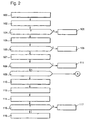
- Figure 3 shows the relationship between the time a contact signal is received and an actuator
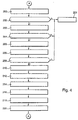
- Figure 4 is a flow chart for Illustration of the operation of the allocation device when teaching new actuators
- Figure 5 the structure of a search signal.
- reference numeral 10 denotes a device, such as one Access control device for a motor vehicle or a Buildings, a computer or other consumer goods.
- Reference number 20 denotes an actuating element here mentioned device, which the device 10 functional assigned.
- An actuator 20 can for example, a transponder.
- Located in device 10 a transceiver 11 for delivery or Receiving contactlessly via a radio link 30 transferable signals.
- a Decoder 12 Connected to its output is a Decoder 12, which is used by the transceiver 11 received, encrypted signals for decoding. Decoder 12 is used to carry out the decryption a memory 31 with the necessary information, especially in the form of a cryptic key code assigned.
- the decrypted signals become one downstream microprocessor 13 supplied, which they evaluates and depending on the result of the evaluation Initiates follow-up action. In particular, he controls the Delivery of signals via the transceiver 11.
- the microprocessor 13 is also a memory 15 assigned. Among other things, a serial number 16, a manufacturer code 17, and a directory 18 with the Group numbers of the device 10 assigned Actuators 20.
- the manufacturer code 17 is assigned and designated by the manufacturer of the device clearly.
- Serial number 16 is characteristic of associated devices 10 and actuators 20, the group numbers are used to distinguish one common device 10 associated actuators 20th with the same serial numbers.
- the transceiver is an encoder 14 switched, also to carry out the coding the memory 31 is connected. Furthermore, the device 10 via an input device 19 to a user Allow access to the microprocessor 13.
- the Input device 19 can, for example, as in FIG. 1 indicated, be designed as a keypad; any other Refinements are also possible.
- the actuating element 20 has a corresponding transmitter / receiver device Transceiver 21 for receiving from the device 10 emitted signals or to emit contactless transmissible signals to the device 10.
- Transceiver 21 Analog to the device is the transceiver 21 a decoder 22 for Decryption of coded signals downstream.
- the decoder connected to a memory 31, the content of which the corresponds to device-side memory 31, and wherein in particular when encrypting signals in device 10 used cryptic key code is stored.
- the Decoder 22 is also connected to a microprocessor 24, which via transceiver 21 and encoder 22nd received signals processed and depending on the result Initiates follow-up action.
- the microprocessor 24 controls in particular the signal output to the device 10 via the Sending / receiving device 21. It is made to listen or Exclude imitations, usually in encrypted form Shape. For this purpose, between microprocessor 24 and Transceiver 21 - analog to the device - on Encoder 23 switched to perform the Coding function also connected to the memory 31 is.
- the microprocessor 24 is still one Memory device 25 assigned. It includes in particular a memory location 16 for storing a serial number, one Storage space 26 for storing a group number and one Storage space 27 for storing a manufacturer code. The latter is by the manufacturer of the actuator 20th forgive and clearly identify that.
- the serial number is one for device 10 and actuators 20 existing overall device characteristic code.
- Radio link 30 for the transmission without contact Signals between the device side Transceiver 11 and the actuating element-side receiving device 21. From the device-side transmitting / receiving device 11 outgoing Signals reach everyone within them at the same time Range of operating elements 20. As signals infrared signals or high-frequency signals are useful used.
- the search signal emitted by the device 10 becomes of all within the range of the radio link 30 located actuators 20 over their Transceivers 21 received. After delivery through the decoder 22 it is all from the microprocessor 24 reached actuators 20 thereupon checks whether the one transmitted with the search signal Serial number with that stored in memory 25 as Serial number 16 which corresponds to the reference signal, Step 104.
- the start bit 35 which is also transmitted is used for Synchronization of the microprocessor 24 with the received one search signal.
- Results in the actuating element 20 in step 104 performed check that the existing in memory 25 Reference serial number 16 not with the one with the search signal transmitted serial number matches, that turns on Actuator 20 in a sleep state, step 101. It takes part in the subsequent communication with the Device 10 no longer part.
- the microprocessor 24 replies in the form of a Contact signal.
- the contact signal is a short one simple signal, for example the group number 26 of the associated actuator 20 in bit-coded form. Like the search signal, it is unencrypted. His
- the processor 24 initiates transmission after the expiry of a for the actuator 20 characteristic period Input of the search signal.
- the sending of the contact signal then takes place in a time window with a predetermined length, Step 105.
- the length of the time window is such that a safe assignment of a contact signal on both sides the actuators 20 as possible on the part of the device is.
- Figure 3 illustrates the function of the actuators 20 following the examination of step 104 in graphic representation.
- the abscissa denotes one divided into eight time windows F0, ..., F7 Time axis t, which with the input of the search signal in the Actuators begin.
- the ordinate gives that characteristic group number 26 of each Actuator 20 on.
- Device 10 eight actuators 20 with the group numbers 0 to 7 assigned. Of these, the actuators 20 with group numbers 2 and 6 when sending one Search signals by the device 10 in the field of action Search signals present. Both operating elements 2 and 6 respond accordingly to the search signal Sending a contact signal according to step 106.
- Im underlying example corresponds to the time of Transmission of the contact signal, i.e.
- the microprocessor 13 now determines those present Actuators 20 by checking which ones Time windows F0, ..., F7 contact signals have been received, Step 106. He checks by repeating m times as many - m - time slots as actuators at most can be assigned, step 107. Attendants Actuators 20 are by corresponding entries noted in memory 15, step 103. If none Actuating element 20 determines, an abort signal is issued, Steps 108, 111. After determining the ones present Actuators 20 determine the Mode of operation, step 109; The operating modes are possible Assigning and teaching as well as other functions such as deleting, Block, release and the like The microprocessor 13 checks this purpose, whether a command to select the operating mode There is learning.
- the Microprocessor 13 makes a decision with which of the Actuators 20 present another Assignment communication is to take place, step 110.
- the basis for the decision can be, for example Ranking of the actuators 20, in which the Actuators 20 about different Functional scope are granted. For example, at Certain use in motor vehicles Actuators 20 a limited geographical Area within which the vehicle is assigned the actuator is functional. That among the Actuators 20 selected Actuating element informs the microprocessor 13 Sending his group number. All if necessary present further actuators 20 with others Group numbers take part in the subsequent communication no longer part.
- the device 10 then subjects the selected one Actuator 20 of a matching test. In the example, this is done using the known challenge-response method.
- the device 10 sets here on his Transceiver 11 an encrypted challenge signal from that for the selected actuator 20 is determined and executed only by this, step 112.
- the device-side microprocessor determines 13 a target response signal. The calculation is made from the Challenge signal according to a predefined algorithm use of the cryptic stored in the memory 31 Key and the available in memory 15 Manufacturer codes 17. In this way the uniqueness of the response signal and thus the distinguishability of the Actuators secured within the group.
- the Challenge signal is meanwhile from the Transmitting / receiving device 21 in the actuating element 20 received in the decoder 22 with the aid of the cryptic key 31 decoded and the microprocessor 24 fed.
- the latter derives from the received challenge signal in the same way as the device side Microprocessor 13 a response signal and sends it to the device 10 back, step 114.
- the transceiver 11 decoded again in the decoder 12 and the microprocessor 13 fed.
- the latter compares it with the previously determined one Target response signal, step 116. Both are not correct match, device 10 and actuator 20 are each other not belonging.
- the processor 13 then directs corresponding ones
- follow-up action for example, he locks the device 10 against use, step 117.
- an assignment is not made is, for example by visual or acoustic display.
- connection measures can also be provided, for example, a repetition of the assignment procedure starting with step 112 or with step 102.
- the device 10, 20, 30 described above permits by Teaching also the assignment of new, especially brand new Actuators 20 to an existing device 10. Die Such a reassignment is carried out in FIG. 4 as Flow chart shown. From the in each process step given addition in the form of the letter G or B. again it can be seen whether the relevant step in the Device 10: G or in actuator 20: B takes place. Teaching actuators to be reassigned 20 initially runs like the assignment shown in FIG units already known to each other and starts with the Triggering a mapping communication according to step 100. It this is followed by the determination of the range of action of the device 10 known actuators 20 according to the Steps 102 to 108. In step 110, however, the Teaching mode defined, step 200.
- the change between the operating modes assignment and teaching expediently by the user with the help of Input device 17.
- the microprocessor then checks 13, step 202, whether a particular one, as Main actuator treated actuator 20 is present.
- the main operating element is, for example Actuator with group number 0, which accordingly after receipt of the search signal in the first Time window F0 sends back a contact signal. Does the Microprocessor 13 determines that the main actuator 20th is not present, it cancels the teach mode.
- step 202 If the check in step 202 reveals that the Main actuator is present, it becomes one Allocation correctness check, step 203, according to steps 112 to 118 subjected. If there is a fault Assignment, the teach mode is aborted, step 201. Proper assignment of main actuator and Detected device, the microprocessor 13 checks using the Directory 18, whether free, not yet Actuator-assigned group numbers available are, and an assignment of further actuators 20 to the device 10 is even possible, step 204. In the case a negative finding, it breaks the learning process again from step 201. If the determination is positive the microprocessor 13 causes a zero search signal to be emitted, Step 205.
- the zero search signal corresponds to in its structure is a search signal, as it is in normal operation Step 104 is discontinued, and is also unencrypted.
- the serial number there is one 20 brand-new serial numbers for brand-new actuators.
- binary serial numbers it in a simple way e.g. from a sequence of zeros. Are in the effective range of radio link 30 Brand new actuators 20, they receive the zero search signal.
- the device 10 checks in the meantime the receipt of on the transmission of the zero search signal incoming contact signals, step 208. Provides the Microprocessor 13 determines that no contact signal received, he cancels the learning process, Step 201. On the other hand, the microprocessor 13 sets the Input of one caused by a zero search signal Contact signal in a time window, he causes the Issuing a control signal, step 210, which immediately all others who may be present Actuators 20 placed in idle state, i.e. also those who have a contact signal in a later Submit time window. The microprocessor 13 repeats then steps 205 to 210 with the determined Actuators 20 a predetermined number of times, i.e.
- the microprocessor 13 initiates the transfer the serial number 16, the cryptic code key 31, and one of the actuating element 20 in the future assigned characteristic group number 26.
- the transmitted code information 16, 26, 31 does that Actuator 20 in the intended up to at this point there are still free spaces in memory 25.
- code information 16, 26, 31 an acknowledgment signal to the device 10. It can be for example, the manufacturer number 27.
- Step 220 the device 10 issues a wake-up command, by means of which the further, if any, in Actuating elements 20 in the sleep state again be activated. It can now learn further actuators 20 to be reassigned Repeat steps 202 and then connect.
- Actuators While maintaining the basic idea, Actuators based on the time of their response to identify a search signal, the prescribed device in various ways design and modify. For example, this applies to the Structure of device and actuators for which Design and sequence of process steps, for example regarding the implementation of the Accessibility check, or for the form and structure the code information exchanged over the radio link.
Landscapes
- Physics & Mathematics (AREA)
- General Physics & Mathematics (AREA)
- Selective Calling Equipment (AREA)
- Lock And Its Accessories (AREA)
Description
Claims (7)
- Vorrichtung zum Zuordnen eines Betätigungselementes zu einem Gerät miteiner im Gerät (10) angeordneten Sendeeinrichtung (11) zur Abgabe eines Suchsignales,einer im Betätigungselement (20) angeordneten Verarbeitungseinrichtung (21 bis 24), die Mittel zum Empfangen von Suchsignalen beinhaltet, und die bei Übereinstimmung eines Suchsignales mit einem vorher festgelegten Referenzsignal ein Kontaktsignal ausgibt, wobei die Verarbeitungseinrichtung (21 bis 24) das Kontaktsignal nach Ablauf einer vorbestimmten Wartezeit (T2, T6) ab dem Eingang des Suchsignales abgibt, dadurch gekennzeichnet, daß das Gerät (10) dazu ausgebildet ist, einem noch nicht zugeordneten Betätigungselement (20) eine das Betätigungselement (20) kennzeichnende Wartezeit zuzuteilen, um es anzulernen.
- Vorrichtung nach Anspruch 1, dadurch gekennzeichnet, daß die Wartezeit (T2, T6) ein bestimmtes Betätigungselement (20) kennzeichnet.
- Vorrichtung nach Anspruch 1, dadurch gekennzeichnet, daß für die Abgabe des Kontaktsignales ein Zeitfenster (F0,...,F7) in Form einer definierten Zeitspanne vorgesehen ist.
- Vorrichtung nach Anspruch 1, dadurch gekennzeichnet, daß das Gerät (10) Auswertemittel (11 bis 14) aufweist, mittels derer es anhand des Zeitpunktes des Einganges eines Kontaktsignales ein bestimmtes Betätigungelement (20) erkennt.
- Vorrichtung nach Anspruch 1, dadurch gekennzeichnet, daß das Gerät (10) nach Erkennen mehrerer Betätigungselemente (20) eines auswählt und mit diesem eine Zuordnungsrichtigkeitsprüfung durchführt.
- Vorrichtung nach Anspruch 1, dadurch gekennzeichnet, daß dem Gerät (10) mechanische, elektrische oder elektrooptische Betätigungsmittel zugeordnet sind, deren Betätigung die Abgabe eines Suchsignales auslöst.
- Vorrichtung nach Anspruch 1, dadurch gekennzeichnet, daß sie das Anlernen eines noch nicht zugeordneten Betätigungselementes (20) nur gestattet, wenn sich ein bestimmtes, bereits zugeordnetes Betätigungselement (20) im Wirkungsbereich des Suchsignales befindet.
Applications Claiming Priority (5)
| Application Number | Priority Date | Filing Date | Title |
|---|---|---|---|
| DE19645769 | 1996-11-07 | ||
| DE19645769 | 1996-11-07 | ||
| DE19743101A DE19743101B4 (de) | 1996-11-07 | 1997-09-30 | Verfahren zum Zuordnen eines Betätigungselementes zu einem Gerät |
| DE19743101 | 1997-09-30 | ||
| PCT/DE1997/002362 WO1998020463A1 (de) | 1996-11-07 | 1997-10-15 | Vorrichtung zum zuordnen eines betätigungselementes zu einem gerät |
Publications (2)
| Publication Number | Publication Date |
|---|---|
| EP0948779A1 EP0948779A1 (de) | 1999-10-13 |
| EP0948779B1 true EP0948779B1 (de) | 2004-06-02 |
Family
ID=26031035
Family Applications (1)
| Application Number | Title | Priority Date | Filing Date |
|---|---|---|---|
| EP97913100A Expired - Lifetime EP0948779B1 (de) | 1996-11-07 | 1997-10-15 | Vorrichtung zum Zuordnen eines Betätigungselementes zu einem Gerät |
Country Status (5)
| Country | Link |
|---|---|
| US (1) | US6982628B1 (de) |
| EP (1) | EP0948779B1 (de) |
| AU (1) | AU716515B2 (de) |
| ES (1) | ES2222506T3 (de) |
| WO (1) | WO1998020463A1 (de) |
Families Citing this family (7)
| Publication number | Priority date | Publication date | Assignee | Title |
|---|---|---|---|---|
| DE19703998A1 (de) * | 1997-02-04 | 1998-08-06 | Bosch Gmbh Robert | Verfahren zum Betrieb einer Fernwirkeinrichtung und Fernwirkeinrichtung |
| DE19962622B4 (de) * | 1999-12-23 | 2004-12-16 | Siemens Ag | Verfahren zum Ermitteln von im Zugriffsbereich einer Anfrageeinheit eines Zugangskontrollsystems befindlichen Datenträgern sowie Zugangskontrollsystem |
| DE10059561B4 (de) * | 2000-11-30 | 2005-08-25 | Siemens Ag | Verfahren zum Betreiben eines Zugangskontrollsystems |
| DE10211930B4 (de) * | 2002-03-18 | 2004-11-04 | Siemens Ag | Verfahren zur Kommunikation zwischen einer Basiseinheit und mehreren Identifikationsgebern eines Zugangskontrollsystems und Zugangskontrollsystem |
| AU2002952753A0 (en) * | 2002-11-19 | 2003-01-16 | Australian Arrow Pty Ltd | Passive entry system |
| US7753245B2 (en) * | 2007-06-22 | 2010-07-13 | Ethicon Endo-Surgery, Inc. | Surgical stapling instruments |
| US9129455B2 (en) * | 2012-02-21 | 2015-09-08 | Fca Us Llc | System and method to enable passive entry |
Family Cites Families (14)
| Publication number | Priority date | Publication date | Assignee | Title |
|---|---|---|---|---|
| US4495496A (en) * | 1981-12-15 | 1985-01-22 | Johnson Engineering Corp. | Personnel monitoring and locating system |
| ATE110480T1 (de) | 1987-03-31 | 1994-09-15 | Identec Ltd | Zugangskontrolleinrichtung. |
| US4837568A (en) | 1987-07-08 | 1989-06-06 | Snaper Alvin A | Remote access personnel identification and tracking system |
| US5357141A (en) * | 1988-04-02 | 1994-10-18 | Robert Bosch Gmbh | Electronic device |
| US4998249A (en) * | 1988-10-28 | 1991-03-05 | Executone Information Systems, Inc. | Method and system for multiplexing telephone line circuits to highway lines |
| SE464946B (sv) * | 1989-11-10 | 1991-07-01 | Philips Norden Ab | Oeverfoeringssystem innefattande en fraagestation och ett antal svarsstationer |
| US5640151A (en) * | 1990-06-15 | 1997-06-17 | Texas Instruments Incorporated | Communication system for communicating with tags |
| US5493283A (en) * | 1990-09-28 | 1996-02-20 | Olivetti Research Limited | Locating and authentication system |
| GB2259227B (en) | 1991-08-30 | 1995-10-18 | Marconi Gec Ltd | Improvements in or relating to transponders |
| DE4392671C2 (de) * | 1992-06-10 | 2000-06-21 | Ford Werke Ag | Kommunikationssystem für Kraftfahrzeuge |
| DE4337637A1 (de) * | 1993-11-04 | 1995-05-11 | Licentia Gmbh | Transponder und Datenkommunikationssystem |
| US5450087A (en) | 1994-04-06 | 1995-09-12 | Texas Instruments Incorporated | Transponder maintenance mode method |
| US5636342A (en) * | 1995-02-17 | 1997-06-03 | Dell Usa, L.P. | Systems and method for assigning unique addresses to agents on a system management bus |
| US5905442A (en) * | 1996-02-07 | 1999-05-18 | Lutron Electronics Co., Inc. | Method and apparatus for controlling and determining the status of electrical devices from remote locations |
-
1997
- 1997-10-15 ES ES97913100T patent/ES2222506T3/es not_active Expired - Lifetime
- 1997-10-15 US US09/297,952 patent/US6982628B1/en not_active Expired - Lifetime
- 1997-10-15 EP EP97913100A patent/EP0948779B1/de not_active Expired - Lifetime
- 1997-10-15 WO PCT/DE1997/002362 patent/WO1998020463A1/de not_active Ceased
- 1997-10-15 AU AU50475/98A patent/AU716515B2/en not_active Expired
Also Published As
| Publication number | Publication date |
|---|---|
| AU716515B2 (en) | 2000-02-24 |
| EP0948779A1 (de) | 1999-10-13 |
| ES2222506T3 (es) | 2005-02-01 |
| US6982628B1 (en) | 2006-01-03 |
| WO1998020463A1 (de) | 1998-05-14 |
| AU5047598A (en) | 1998-05-29 |
Similar Documents
| Publication | Publication Date | Title |
|---|---|---|
| DE3851168T2 (de) | Zugangskontrolleinrichtung. | |
| DE10103044A1 (de) | Vorrichtung zur benutzerspezifischen Aktivierung von Fahrzeugfunktionen | |
| DE3119876A1 (de) | "infrarot-sende-empfangssystem" | |
| EP1302374A2 (de) | Verfahren zum Initialisieren eines Zugangskontrollsystems mit mehreren elektronischen Schlüsseln und mehreren Objekten | |
| DE112007001015T5 (de) | Verfahren zum Bedienen einer Mehrzahl von Fahrzeugen mittels eines beliebigen Senders aus einer programmierten Gruppe | |
| EP1002177B1 (de) | Verfahren zum betrieb einer fernbedienung, und fernbedienung | |
| DE19703999A1 (de) | Verfahren und Vorrichtung zum Zuordnen einer Berechtigungseinrichtung zu einer Basisstation | |
| DE19743101B4 (de) | Verfahren zum Zuordnen eines Betätigungselementes zu einem Gerät | |
| EP0948779B1 (de) | Vorrichtung zum Zuordnen eines Betätigungselementes zu einem Gerät | |
| DE10143727B4 (de) | Im Fahrzeug mitgeführtes Schlüsselprüfsystem mit Prüfungshistorienspeicher | |
| EP0877331B1 (de) | Drahtloses Datenübertragungssystem | |
| EP0891607B1 (de) | Verfahren zum betrieb einer fernwirkeinrichtung und fernwirkeinrichtung | |
| DE102008053369A1 (de) | Verfahren zur Challenge-Response-Authentisierung zwischen einem Lesegerät und einem Transponder basierend auf einer kontaktlosen Datenübertragung | |
| DE19652227A1 (de) | Verfahren und Vorrichtung zum Zuordnen einer Fernbedienung zu einer Basisstation | |
| EP1484858A1 (de) | Verfahren zum funktionellen Verheiraten der Komponenten einer Authentisierungseinrichtung miteinander sowie Authentisierungseinrichtung | |
| EP0923054B1 (de) | Verfahren und Vorrichtung zur Prüfung der Nutzungsberechtigung für Zugangskontrolleinrichtungen | |
| DE4325221C2 (de) | Verfahren zum Einlesen einer Codierung eines Codeträgers in eine Identifizierungseinrichtung eines Kraftfahrzeuges und Identifizierungseinrichtung zur Durchführung des Verfahrens | |
| EP1006248A1 (de) | Fernsteuerbare Zugangskontrolleinrichtung, insbesondere für ein Kraftfahrzeug, und hierfür ausgelegter, tragbarer Transponder | |
| DE3536378A1 (de) | Sicherheitseinrichtung fuer ein kraftfahrzeug | |
| DE102007006714B4 (de) | Verfahren zum Anlernen eines Funk-Schlüssels an ein Fahrzeug sowie entsprechender Funk-Schlüssel und entsprechendes Fahrzeug | |
| DE10004615C2 (de) | Berechtigungskontrollsystem, insbesondere für ein Kraftfahrzeug | |
| EP0813170A2 (de) | Elektronisches Zugangsberechtigungssystem und Verfahren zum Feststellen eines berechtigten Zugangs | |
| EP0879160B2 (de) | Diebstahlsicherungseinrichtung für kraftfahrzeuge sowie verfahren zur diebstahlsicherung | |
| EP1017916B1 (de) | Verfahren zum zuordnen einer fernbedienung zu einer basisstation | |
| EP0773148A1 (de) | Sicherungsvorrichtung für ein Kraftfahrzeug |
Legal Events
| Date | Code | Title | Description |
|---|---|---|---|
| PUAI | Public reference made under article 153(3) epc to a published international application that has entered the european phase |
Free format text: ORIGINAL CODE: 0009012 |
|
| 17P | Request for examination filed |
Effective date: 19990607 |
|
| AK | Designated contracting states |
Kind code of ref document: A1 Designated state(s): DE ES FR GB IT SE |
|
| RTI1 | Title (correction) |
Free format text: DEVICE FOR ASSIGNING AN OPERATING ELEMENT TO AN APPARATUS |
|
| GRAG | Despatch of communication of intention to grant |
Free format text: ORIGINAL CODE: EPIDOS AGRA |
|
| RTI1 | Title (correction) |
Free format text: DEVICE FOR ASSIGNING AN OPERATING ELEMENT TO AN APPARATUS |
|
| 17Q | First examination report despatched |
Effective date: 20000913 |
|
| GRAG | Despatch of communication of intention to grant |
Free format text: ORIGINAL CODE: EPIDOS AGRA |
|
| GRAG | Despatch of communication of intention to grant |
Free format text: ORIGINAL CODE: EPIDOS AGRA |
|
| GRAH | Despatch of communication of intention to grant a patent |
Free format text: ORIGINAL CODE: EPIDOS IGRA |
|
| GRAH | Despatch of communication of intention to grant a patent |
Free format text: ORIGINAL CODE: EPIDOS IGRA |
|
| GRAA | (expected) grant |
Free format text: ORIGINAL CODE: 0009210 |
|
| AK | Designated contracting states |
Kind code of ref document: B1 Designated state(s): DE ES FR GB IT SE |
|
| REG | Reference to a national code |
Ref country code: GB Ref legal event code: FG4D Free format text: NOT ENGLISH |
|
| REF | Corresponds to: |
Ref document number: 59711693 Country of ref document: DE Date of ref document: 20040708 Kind code of ref document: P |
|
| REG | Reference to a national code |
Ref country code: SE Ref legal event code: TRGR |
|
| GBT | Gb: translation of ep patent filed (gb section 77(6)(a)/1977) |
Effective date: 20040823 |
|
| ET | Fr: translation filed | ||
| REG | Reference to a national code |
Ref country code: ES Ref legal event code: FG2A Ref document number: 2222506 Country of ref document: ES Kind code of ref document: T3 |
|
| PLBE | No opposition filed within time limit |
Free format text: ORIGINAL CODE: 0009261 |
|
| STAA | Information on the status of an ep patent application or granted ep patent |
Free format text: STATUS: NO OPPOSITION FILED WITHIN TIME LIMIT |
|
| 26N | No opposition filed |
Effective date: 20050303 |
|
| PGFP | Annual fee paid to national office [announced via postgrant information from national office to epo] |
Ref country code: FR Payment date: 20101109 Year of fee payment: 14 |
|
| PGFP | Annual fee paid to national office [announced via postgrant information from national office to epo] |
Ref country code: GB Payment date: 20101021 Year of fee payment: 14 Ref country code: IT Payment date: 20101023 Year of fee payment: 14 Ref country code: SE Payment date: 20101021 Year of fee payment: 14 |
|
| PGFP | Annual fee paid to national office [announced via postgrant information from national office to epo] |
Ref country code: ES Payment date: 20101021 Year of fee payment: 14 |
|
| GBPC | Gb: european patent ceased through non-payment of renewal fee |
Effective date: 20111015 |
|
| REG | Reference to a national code |
Ref country code: SE Ref legal event code: EUG |
|
| REG | Reference to a national code |
Ref country code: FR Ref legal event code: ST Effective date: 20120629 |
|
| PG25 | Lapsed in a contracting state [announced via postgrant information from national office to epo] |
Ref country code: GB Free format text: LAPSE BECAUSE OF NON-PAYMENT OF DUE FEES Effective date: 20111015 Ref country code: FR Free format text: LAPSE BECAUSE OF NON-PAYMENT OF DUE FEES Effective date: 20111102 Ref country code: IT Free format text: LAPSE BECAUSE OF NON-PAYMENT OF DUE FEES Effective date: 20111015 |
|
| PG25 | Lapsed in a contracting state [announced via postgrant information from national office to epo] |
Ref country code: SE Free format text: LAPSE BECAUSE OF NON-PAYMENT OF DUE FEES Effective date: 20111016 |
|
| REG | Reference to a national code |
Ref country code: ES Ref legal event code: FD2A Effective date: 20130417 |
|
| PG25 | Lapsed in a contracting state [announced via postgrant information from national office to epo] |
Ref country code: ES Free format text: LAPSE BECAUSE OF NON-PAYMENT OF DUE FEES Effective date: 20111016 |
|
| PGFP | Annual fee paid to national office [announced via postgrant information from national office to epo] |
Ref country code: DE Payment date: 20161213 Year of fee payment: 20 |
|
| REG | Reference to a national code |
Ref country code: DE Ref legal event code: R071 Ref document number: 59711693 Country of ref document: DE |