EP0948887B1 - Dispositif autonome de distribution de produits de traitement en enceinte fermée et système de positionnement dudit dispositif - Google Patents
Dispositif autonome de distribution de produits de traitement en enceinte fermée et système de positionnement dudit dispositif Download PDFInfo
- Publication number
- EP0948887B1 EP0948887B1 EP99390006A EP99390006A EP0948887B1 EP 0948887 B1 EP0948887 B1 EP 0948887B1 EP 99390006 A EP99390006 A EP 99390006A EP 99390006 A EP99390006 A EP 99390006A EP 0948887 B1 EP0948887 B1 EP 0948887B1
- Authority
- EP
- European Patent Office
- Prior art keywords
- positioning system
- fact
- rail
- pantograph
- autonomous
- Prior art date
- Legal status (The legal status is an assumption and is not a legal conclusion. Google has not performed a legal analysis and makes no representation as to the accuracy of the status listed.)
- Expired - Lifetime
Links
- 230000008878 coupling Effects 0.000 claims abstract description 12
- 238000010168 coupling process Methods 0.000 claims abstract description 12
- 238000005859 coupling reaction Methods 0.000 claims abstract description 12
- 239000007921 spray Substances 0.000 claims description 7
- 238000010408 sweeping Methods 0.000 claims description 3
- 238000006073 displacement reaction Methods 0.000 claims description 2
- 239000007788 liquid Substances 0.000 claims description 2
- 239000000843 powder Substances 0.000 claims description 2
- 238000011084 recovery Methods 0.000 claims description 2
- 230000035939 shock Effects 0.000 claims description 2
- 125000006850 spacer group Chemical group 0.000 claims description 2
- 239000003638 chemical reducing agent Substances 0.000 claims 3
- 230000000284 resting effect Effects 0.000 claims 2
- 238000010521 absorption reaction Methods 0.000 claims 1
- 230000007547 defect Effects 0.000 claims 1
- 238000010248 power generation Methods 0.000 claims 1
- 239000000725 suspension Substances 0.000 claims 1
- 238000012545 processing Methods 0.000 description 7
- 231100000925 very toxic Toxicity 0.000 description 3
- 238000009434 installation Methods 0.000 description 2
- 238000012546 transfer Methods 0.000 description 2
- 238000013519 translation Methods 0.000 description 2
- 241000239290 Araneae Species 0.000 description 1
- 239000006096 absorbing agent Substances 0.000 description 1
- 230000015572 biosynthetic process Effects 0.000 description 1
- 230000007423 decrease Effects 0.000 description 1
- 239000012530 fluid Substances 0.000 description 1
- 238000012423 maintenance Methods 0.000 description 1
- 239000002184 metal Substances 0.000 description 1
- 230000004224 protection Effects 0.000 description 1
- 230000001681 protective effect Effects 0.000 description 1
- 229910001220 stainless steel Inorganic materials 0.000 description 1
- 239000010935 stainless steel Substances 0.000 description 1
- 238000012549 training Methods 0.000 description 1
- 235000013311 vegetables Nutrition 0.000 description 1
Images


Classifications
-
- A—HUMAN NECESSITIES
- A01—AGRICULTURE; FORESTRY; ANIMAL HUSBANDRY; HUNTING; TRAPPING; FISHING
- A01G—HORTICULTURE; CULTIVATION OF VEGETABLES, FLOWERS, RICE, FRUIT, VINES, HOPS OR SEAWEED; FORESTRY; WATERING
- A01G9/00—Cultivation in receptacles, forcing-frames or greenhouses; Edging for beds, lawn or the like
- A01G9/24—Devices or systems for heating, ventilating, regulating temperature, illuminating, or watering, in greenhouses, forcing-frames, or the like
- A01G9/247—Watering arrangements
-
- Y—GENERAL TAGGING OF NEW TECHNOLOGICAL DEVELOPMENTS; GENERAL TAGGING OF CROSS-SECTIONAL TECHNOLOGIES SPANNING OVER SEVERAL SECTIONS OF THE IPC; TECHNICAL SUBJECTS COVERED BY FORMER USPC CROSS-REFERENCE ART COLLECTIONS [XRACs] AND DIGESTS
- Y02—TECHNOLOGIES OR APPLICATIONS FOR MITIGATION OR ADAPTATION AGAINST CLIMATE CHANGE
- Y02A—TECHNOLOGIES FOR ADAPTATION TO CLIMATE CHANGE
- Y02A40/00—Adaptation technologies in agriculture, forestry, livestock or agroalimentary production
- Y02A40/10—Adaptation technologies in agriculture, forestry, livestock or agroalimentary production in agriculture
- Y02A40/25—Greenhouse technology, e.g. cooling systems therefor
Definitions
- the present invention relates to an autonomous device for distribution of treatment products in closed enclosure and its positioning.
- a positioning system of an autonomous device distribution of treatment products with the features of the preamble of claim 1 is known for example from document DE-U-8700020.
- the present invention relates to a positioning system three-dimensional of said device, associated for example with a coupling capable of also support storage of treatment products.
- the present invention it is therefore not necessary to multiply the number of treatment devices by the number of greenhouses, only the horizontal rail remains in place. Furthermore, this device makes it possible to treat completely and regularly a greenhouse in a few minutes, without expose personnel who may remain outside the enclosure. Finally, the extendable ramp allows the device to be inserted in a conventional greenhouse, through the access door, then by extension to fully cover the width of the greenhouse. This folded device is therefore very compact and can easily hold on a mobile hitch for example to be moved from a greenhouse to a other.
- the autonomous treatment system ( Figures 1 and 2) is composed of an autonomous mobile (1) guided on a rail horizontal (2) and a processing tool (3) connected to the autonomous mobile and distributing products.
- the processing tool can be a laterally extendable ramp (3) provided with means for distributing products (4) or a high pressure spray module for example.
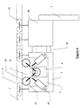
- the autonomous mobile (1) is driven by a motor assembly (5) guided by four rollers (6) inside the rail (2) ( Figure 3 and 4).
- the movement of the mobile is ensured by rollers (7) carrying a belt bearing on the upper internal part of the rail (1), so that form a caterpillar.
- the belt (9) is rotated by a gear motor (8).
- the grip pressure exerted by the belt (9) on the rail is provided by two jacks (10).
- the air pressure setting in these jacks make it possible to vary the pressure between the rollers (7) and the rail (2) to obtain optimal grip.
- these cylinders play a role shock absorber to compensate for certain faults in the guidance while ensuring the grip necessary for training.
- the autonomous mobile is driven by grip wheels (40) supported on the external surface of the lower part of the rail (2).
- the wheels (40) are driven by belts (41) connected to a geared motor (8).
- the wheels (40) are held by articulated links (42). On each link, a cylinder (43) allows to exert an adhesion pressure.
- the autonomous mobile is controlled from outside the enclosure by a control console (11).
- the guide rail (2) of the mobile is located about two meters high, in the middle of the greenhouse in the longitudinal axis. It can be attached directly to the amounts of the greenhouse or maintained by an independent structure.
- This rail is a profile rectangular of dimensions 50mm by 40mm for example, split on its lower part.
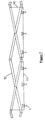
- the autonomous mobile (1) can support an extendable ramp (figure 2) composed of a series of cross-pieces (12) forming parallelograms deformable. Each crosspiece has three axes of rotation (13), one at middle and one at each end. Each of these rotation points is linked at the corresponding rotation points of the neighboring braces.
- the assembly of several braces according to this principle forms a deformable structure laterally.
- the deployment of the ramp is effected by two cylinders (14) linked to the axes (15) from the middle of the braces forming the parallelogram from the center of the ramp.
- the ramp is Conversely, when these two points converge, the ramp folds up.
- the deployment of the ramp is ensured by three cylinders, a central cylinder (45) and two lateral cylinders (44) and (44 ').
- the base of each cylinder is hinged on a support (46).
- the central cylinder rod is articulated on the pivot point lower (47) from the center of the ramp.
- the side cylinder rods are articulated on the intermediate pivot points (48) and (48 ') of the middle of the ramp.
- the folded ramp allows to pass through a classic access of greenhouse about 1.5m wide. When the ramp is deployed, its width is more than quadrupled.
- the ramp consists of two parallel series of braces (16) separated by spacers (17). Starting from the center of the ramp in both directions, each cross is mounted on the inside of the previous cross. The width of the ramp therefore decreases outwards.
- This form of realization allows to obtain a more rigid structure.
- the deployment cylinders (14) are located between the two sets of spiders, the deployment efforts are thus symmetrical and better distributed.
- the cross-pieces can be made in section profile square 20mm by 20mm in stainless steel for example.
- the extendable ramp is equipped with means for distributing products (4).
- These distribution means can for example be nozzles of projection of liquids, distributors with rotating discs for projection powders, or even treatment cannons for crops high for example.
- the means of product distribution can be mounted directly on the braces or can be mounted on rods (40) shown in Figure 7.
- the distribution means of products are then slidably mounted on the rods which allows adjust their lateral position.
- the rods (40) can be tubes of metal fixed to the braces.
- the extendable ramp is fitted with a recovery (22) to avoid spreading the little product which nozzles still flow when the boom is folded.
- the extendable ramp can be replaced by any other type of tool like seeders or even a high-spray module pressure.
- the use of high pressure allows the formation of a very fine and swirling fog allowing to deposit fines droplets on all parts of the crop even under the leaves.
- We in this case means by high pressure, a pressure of about 100 bars per example.
- the high pressure spray module consists of nozzles projection capable of sweeping from top to bottom and from left to right. The height of the nozzles can be variable and these can for example be located between 1 and 2m from the ground. According to a mode of embodiment of the invention, the nozzles are mounted on rods articulated and the sweeping movement is ensured by jacks.
- the gear motor (8) by a high pressure turbine to drive the mobile autonomous (1).
- the routing of products from a storage tank to the distribution means (4) is done by through a flexible pipe (18) ( Figure 2) forming loops suspended from the rail by lines (19) which slide in this rail.
- the distribution of products from the flexible pipe (18) to the nozzles (4) is made by pipes (20), smaller and provided with articulated connections (21) allowing them to follow the movements of the braces (12).
- the tank can be directly fixed on the autonomous mobile.
- the processing tool can be detached from the autonomous mobile (1) simply by means of bolts (23).
- each processing tool (3) is mounted on a carriage guided by rollers (49).
- the cart and autonomous mobile can be connected to each other by any type coupling (50) such as an elastic coupling for example. It is therefore possible to have a store of mounted treatment tools on independent rails to assemble the desired tool without having to wear it manually.
- the present invention relates to a positioning system ( Figure 8).
- This positioning system is composed of a three-dimensional positioning gantry (24) and a coupling device (25).
- the positioning gantry is made up of three guides allowing movement in three dimensions.
- the autonomous mobile is then supported by a transport rail (26) on the gantry, identical to the guide rail present in the greenhouse.
- the lateral guide (27) and the vertical guide (28) allow the rails (2) and (26) to be aligned.
- the longitudinal guide (29) makes it possible to join the ends of the rails.
- the end of the transport rail (26) is provided with a positioning cone (30), allowing perfect alignment of the two rails.
- the actuators allowing these movements can be cylinders, hydraulic or pneumatic, or geared motors with pinion and rack.
- the control of each actuator is done from a control console (11).
- the invention also provides for an automated positioning of the mobile on the rail by means of sensors making it possible to automatically align the transport rail (26) located on the gantry and
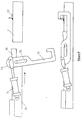
- the coupling device (25) ( Figure 9) allows to join the ends of the two rails.
- the end of the guide rail (2) is provided with a bar (32) welded perpendicular to the rail.
- the hooks (33) located on each side of the transport rail are rotated to align with the rail, then a translational movement to grip the bar (32) and thus ensure the maintenance of the whole. These movements are ensured by jacks (34) articulated at the end of the hooks and lights (35) machined in the hooks.
- the present invention also relates to a mobile assembly (36) (FIG. 8) supporting the positioning system, the control console (11), means for producing electrical energy (37) which may be a generator or an alternator connected to the PTO of a tractor, one or more pneumatic and / or hydraulic compressors (38) as well as one or more product tanks (39).
- the mobile assembly can be hitched behind a tractor, but it can also be motorized and guided on rails on the ground for example to allow an autonomous passage from one greenhouse to another.
Landscapes
- Life Sciences & Earth Sciences (AREA)
- Environmental Sciences (AREA)
- Guiding Agricultural Machines (AREA)
- Sampling And Sample Adjustment (AREA)
- Heat Treatment Of Articles (AREA)
- Electroplating Methods And Accessories (AREA)
- Electrical Discharge Machining, Electrochemical Machining, And Combined Machining (AREA)
- Greenhouses (AREA)
- Container Filling Or Packaging Operations (AREA)
- Catching Or Destruction (AREA)
- Feeding, Discharge, Calcimining, Fusing, And Gas-Generation Devices (AREA)
Description
- un mobile autonome pouvant être mis en place sur un rail de guidage horizontal et se déplaçant sur ledit rail horizontal interne à l'enceinte, ledit mobile pouvant être commandé de l'extérieur après fermeture de l'enceinte et pouvant être retiré du rail de guidage après traitement pour être installé dans une autre enceinte.
- un outil de traitement relié au mobile autonome et assurant la distribution de produit .
- la figure 1 représente la rampe déployée à l'intérieur de la serre.
- la figure 2 représente en perspective le mobile autonome, la rampe repliée ainsi qu'une partie du dispositif d'accouplement.
- la figure 3 représente le mobile autonome et l'ensemble moteur.
- la figure 4 représente un autre mode de réalisation du système d'entraínement du mobile autonome.
- la figure 5 représente une autre forme de réalisation de la rampe extensible.
- la figure 6 représente un autre mode de réalisation du système de déploiement de la rampe extensible.
- la figure 7 représente un système adaptable à la rampe permettant de faire varier la distance entre les moyens de distribution de produits.
- la figure 8 représente le portique de positionnement ainsi que l'ensemble mobile attelable.
- la figure 9 représente le dispositif d'accouplement du mobile autonome sur le rail de guidage.
Les actionneurs permettant ces déplacements peuvent être des vérins, hydrauliques ou pneumatiques, ou des motoréducteurs avec pignon et crémaillère. La commande de chaque actionneur se fait depuis un pupitre de commande (11). L'invention prévoit également un positionnement automatisé du mobile sur le rail par l'intermédiaire de capteurs permettant d'aligner automatiquement le rail de transport (26) situé sur le portique et le rail de guidage (2).
L'extrémité du rail de guidage (2) est pourvue d'une barre (32) soudée perpendiculairement au rail. Les crochets (33) situés de chaque coté du rail de transport sont animés d'un mouvement de rotation pour s'aligner avec le rail, puis d'un mouvement de translation permettant de saisir la barre (32) et d'assurer ainsi le maintien de l'ensemble. Ces mouvements sont assurés par des vérins (34) articulés à l'extrémité des crochets et des lumières (35) usinées dans les crochets.
- Positionnement automatique du rail de transport et du rail de guidage
- Accouplement
- Translation du mobile autonome jusqu'à l'intérieur de la serre.
- Déploiement de la rampe
- Mise en route des moyens de distribution de produits
- Translation du mobile autonome jusqu'au fond de la serre
- Arrêt des moyens de distribution
- Repliage de la rampe
- Retour rapide du mobile autonome
- Désaccouplement
- Retour du portique en position de transport
L'ensemble mobile peut être attelé derrière un tracteur, mais il peut être également motorisé et guidé sur des rails au sol par exemple pour permettre un passage autonome d'une serre à une autre.
Claims (28)
- Système de positionnement d'un dispositif autonome de distribution de produits de traitement en enceinte fermée, ledit dispositif autonome comprenant :ledit système de positionnement étant caractérisé en ce qu'il comprend:un mobile autonome (1) pouvant être mis en place sur un rail de guidage horizontal (2) et se déplaçant sur ledit rail horizontal interne à l'enceinte, ledit mobile pouvant être commandé de l'extérieur après fermeture de l'enceinte et pouvant être retiré du rail de guidage après traitement pour être installé dans une autre enceinte.un outil de traitement (3) relié au mobile autonome et assurant la distribution de produitun portique de positionnement tridimensionnel (24)un dispositif d'accouplement (25) du mobile autonome (1) sur le rail de guidage horizontal (2).
- Ensemble mobile caractérisé en ce qu'il supporte le système de positionnement selon la revendication 1, un pupitre de commande (11), des moyens de production d'énergie électrique (37) pouvant être un groupe électrogène ou un alternateur relié à la prise de force d'un tracteur, un ou plusieurs compresseurs (38) pneumatiques et/ou hydrauliques ainsi qu'un ou plusieurs réservoirs de produits (39).
- Système de positionnement selon la revendication 1 caractérisé en ce que l'outil de traitement est une rampe extensible latéralement (3) dotée de moyens de distribution de produits (4) relié à un réservoir de stockage (39) des dits produits.
- Système de positionnement selon la revendication 1 caractérisé en ce que l'outil de traitement est un module d'aspersion à haute pression.
- Système de positionnement selon la revendication 1 ou la revendication 3 ou la revendication 4 caractérisé en ce que le mobile autonome (1) est entraíné par un ensemble moteur (5) guidé par quatre galets (6) à l'intérieur du rail (2), le déplacement dudit mobile étant assuré par des galets (7) portant une courroie (9) prenant appui sur la partie interne supérieure du rail, ladite courroie (9) étant entraínée en rotation par un motoréducteur (8).
- Système de positionnement selon la revendication 1 ou la revendication 3 ou la revendication 4 caractérisé en ce que le mobile autonome (1) est entraíné par un ensemble moteur (5) guidé par quatre galets (6) à l'intérieur du rail (2), le déplacement dudit mobile étant assuré par des roues d'adhérence (40) prenant appui sur la partie inférieure externe du rail, lesdites roues étant entraínée en rotation par des courroies (41) reliées à un motoréducteur (8).
- Système de positionnement selon la revendication 4 caractérisé en ce que le mobile autonome est entraíné par une turbine à haute pression.
- Système de positionnement selon la revendication 5 caractérisé en ce que la pression d'adhérence exercée par les galets (7) sur le rail est assurée par des vérins (10), le réglage de la pression d'air dans ces vérins permet de faire varier la pression entre les galets (7) et le rail (2) pour obtenir l'adhérence optimale, ces vérins jouent en outre un rôle d'amortisseur permettant de compenser certains défauts dans le guidage tout en assurant l'adhérence nécessaire pour l'entraínement.
- Système de positionnement selon la revendication 6 caractérisé en ce que la pression d'adhérence exercée par les roues (40) sur le rail est assurée par des vérins (43), articulés sur les biellettes articulées (42) supportant les roues (40).
- Système de positionnement selon la revendication 3 caractérisé en ce que la rampe extensible est composée d'une ou plusieurs séries de croisillons (12) formant des parallélogrammes déformables, chaque croisillon comportant trois axes de rotation (13), un au milieu et un à chaque extrémité, chacun de ces points de rotation étant lié aux points de rotation correspondants des croisillons voisins, l'assemblage de plusieurs croisillons selon ce principe formant une structure déformable latéralement.
- Système de positionnement selon la revendication 10 caractérisé en ce que la rampe est constituée de deux séries parallèles de croisillons (16) écartées par des entretoises (17), cette forme de réalisation permettant d'obtenir une structure plus rigide.
- Système de positionnement selon la revendication 10 ou la revendication 11 caractérisé en ce que le déploiement de la rampe s'effectue grâce à deux vérins (14) liés aux axes (15) du milieu des croisillons formant le parallélogramme du centre de la rampe, par déplacement de ces deux points d'articulation selon une direction horizontale dans des sens opposés divergeants, la rampe se déploie, et inversement, lorsque ces deux points convergent, la rampe se replie.
- Système de positionnement selon la revendication 10 ou la revendication 11 caractérisé en ce que le déploiement de la rampe s'effectue grâce à trois vérins (44), (44') et (45) articulés sur un support (46) et articulés respectivement au point de pivot inférieur (47) du centre de la rampe et aux points de pivot intermédiaires (48) et (48') du milieu de la rampe.
- Système de positionnement selon la revendication 3 caractérisé en ce que la rampe repliée permet de passer au travers d'un accès classique de serre d'environ 1,5m de large.
- Système de positionnement selon la revendication 3 caractérisé en ce que les moyens de distribution de produits (4) peuvent être des buses de projection de liquides, des distributeurs à disques rotatifs pour la projection de poudre ou des canons de traitement pour les cultures hautes.
- Système de positionnement selon la revendication 1 caractérisé en ce que l'acheminement des produits depuis un réservoir de stockage (39), non porté par le mobile autonome, vers le moyen de distribution (4) se fait par l'intermédiaire d'une conduite souple (18) formant des boucles suspendues au rail par des suspentes (19) qui coulissent dans ce rail.
- Système de positionnement selon la revendication 1 caractérisé en ce que le réservoir de produits peut être directement fixé sur le mobile autonome.
- Système de positionnement selon la revendication 3 caractérisé en ce que la rampe extensible (3) est dotée d'un bac de récupération (22).
- Système de positionnement selon la revendication 1 caractérisé en ce que l'outil de traitement est désolidarisable du mobile autonome par l'intermédiaire de boulons (23).
- Système de positionnement selon la revendication 1 caractérisé en ce que l'outil de traitement est monté sur un chariot (48) guidé par des galets (49) et relié au mobile autonome par un accouplement (50).
- Système de positionnement selon la revendication 1 caractérisé en ce que le portique de positionnement (24) est constitué de trois guidages permettant un déplacement dans les trois dimensions, les actionneurs permettant ces déplacements pouvant être des vérins, hydrauliques ou pneumatiques, ou de motoréducteurs avec pignon et crémaillère.
- Système de positionnement selon la revendication 1 caractérisé en ce que le mobile autonome (1) est soutenu par un rail de transport (26), fixé au portique (24), identique au rail de guidage (2), l'extrémité du dit rail (26) étant pourvu d'un cône de positionnement (30).
- Système de positionnement selon la revendication 1 caractérisé en ce que la commande des actionneurs peut se faire manuellement depuis un pupitre de commande (11) ou automatiquement grâce à des capteurs de positionnement.
- Système de positionnement selon la revendication 1 caractérisé en ce que le dispositif d'accouplement (25) est constitué:d'une barre (32) fixée perpendiculairement à l'extrémité du rail de guidage (2).d'un ou plusieurs crochets (33) situés à l'extrémité du rail de transport (26).
- Ensemble mobile selon la revendication 2 caractérisé en ce que le dit ensemble mobile peut être attelé derrière un tracteur ou peut être également motorisé et guidé sur des rails au sol par exemple pour permettre un passage autonome d'une serre à une autre.
- Ensemble constitué du dispositif autonome, du système de positionnement et de l'ensemble mobile, respectivement selon les revendications 1, 2 caractérisé en ce que l'ensemble des actionneurs peut être commandé manuellement depuis un pupitre de commande (11), ou être totalement automatisé et géré par un automate programmable ou une commande câblée, composée de plusieurs contacteurs électriques.
- Système de positionnement selon la revendication 3 caractérisé en ce que les moyens de distribution de produits (4) sont montés coulissants sur des tringles (40), permettant de déplacer les dits moyens de distribution latéralement.
- Système de positionnement selon la revendication 4 caractérisé en ce que le module d'aspersion à haute pression est constitué de buses de projection pouvant effectuer un mouvement de balayage de haut en bas et de gauche à droite.
Applications Claiming Priority (2)
| Application Number | Priority Date | Filing Date | Title |
|---|---|---|---|
| FR9804239 | 1998-04-06 | ||
| FR9804239A FR2776890B1 (fr) | 1998-04-06 | 1998-04-06 | Dispositif autonome de distribution de produits de traitement en enceinte fermee et systeme de positionnement dudit dispositif |
Publications (2)
| Publication Number | Publication Date |
|---|---|
| EP0948887A1 EP0948887A1 (fr) | 1999-10-13 |
| EP0948887B1 true EP0948887B1 (fr) | 2001-09-12 |
Family
ID=9524891
Family Applications (1)
| Application Number | Title | Priority Date | Filing Date |
|---|---|---|---|
| EP99390006A Expired - Lifetime EP0948887B1 (fr) | 1998-04-06 | 1999-04-01 | Dispositif autonome de distribution de produits de traitement en enceinte fermée et système de positionnement dudit dispositif |
Country Status (4)
| Country | Link |
|---|---|
| EP (1) | EP0948887B1 (fr) |
| AT (1) | ATE205361T1 (fr) |
| DE (1) | DE69900271D1 (fr) |
| FR (1) | FR2776890B1 (fr) |
Families Citing this family (5)
| Publication number | Priority date | Publication date | Assignee | Title |
|---|---|---|---|---|
| DE10013800A1 (de) * | 2000-03-20 | 2001-10-04 | Holder Gmbh Geb | Fahrbare Vorrichtung zum Ausbringen einer Flüssigkeit |
| NL1039148C2 (nl) * | 2011-11-01 | 2013-05-06 | Klimrek I E B V | Oplossing voor het ophangen van slangen en/ of kabels tijdens werkzaamheden. |
| US9622398B2 (en) | 2014-06-10 | 2017-04-18 | Agbotic, Inc. | Robotic gantry bridge for farming |
| FI127985B (fi) * | 2017-11-22 | 2019-06-28 | Koiviston Hautaustoimisto Om Jaana Hyvoesaho | Kastelulaite ja kokoonpano |
| CN113976347B (zh) * | 2021-09-30 | 2023-12-01 | 安徽哈大智能科技有限公司 | 一种养殖猪舍环境巡检消毒机器人 |
Family Cites Families (6)
| Publication number | Priority date | Publication date | Assignee | Title |
|---|---|---|---|---|
| DE2206275A1 (de) * | 1972-02-10 | 1973-08-16 | Winter Hans Juergen | Beregnungsvorrichtung fuer gewaechshaeuser |
| US4074856A (en) * | 1976-08-05 | 1978-02-21 | Union Carbide Corporation | Greenhouse watering apparatus |
| US4723714A (en) * | 1986-09-25 | 1988-02-09 | Lucas Gary H | Programmable sprinkler system |
| DE8700020U1 (de) * | 1987-01-02 | 1987-05-27 | Krug, Reinhard, Dipl.-Agr.-Ing., 8587 Creußen | Ferngesteuertes Spritzgerät |
| DE3814203A1 (de) * | 1988-04-27 | 1989-11-09 | Henssler Gmbh & Co Kg Gewaechs | Gewaechshaustisch mit pflegevorrichtung insbesondere spruehgeraet |
| DE8915518U1 (de) * | 1989-03-30 | 1990-11-08 | Jülich, Wilhelm, 5000 Köln | Beregnungseinrichtung für Hallen mit Wasser aufnehmendem Bodenbelag |
-
1998
- 1998-04-06 FR FR9804239A patent/FR2776890B1/fr not_active Expired - Lifetime
-
1999
- 1999-04-01 AT AT99390006T patent/ATE205361T1/de not_active IP Right Cessation
- 1999-04-01 DE DE69900271T patent/DE69900271D1/de not_active Expired - Lifetime
- 1999-04-01 EP EP99390006A patent/EP0948887B1/fr not_active Expired - Lifetime
Also Published As
| Publication number | Publication date |
|---|---|
| FR2776890B1 (fr) | 2000-05-19 |
| DE69900271D1 (de) | 2001-10-18 |
| EP0948887A1 (fr) | 1999-10-13 |
| ATE205361T1 (de) | 2001-09-15 |
| FR2776890A1 (fr) | 1999-10-08 |
Similar Documents
| Publication | Publication Date | Title |
|---|---|---|
| DE68917027T2 (de) | Reinigung einer Rohrleitungsoberfläche mit Wasser zur Entfernung von Deckschichten. | |
| MX2014014864A (es) | Ambiente controlado y metodo. | |
| EP2225933B1 (fr) | Dispositif de taille embarqué | |
| EP0461964A1 (fr) | Véhicule autopropulsé et articulé à vérins télescopiques pour l'inspection de tuyauteries | |
| EP0948887B1 (fr) | Dispositif autonome de distribution de produits de traitement en enceinte fermée et système de positionnement dudit dispositif | |
| FR2634623A1 (fr) | Dispositif mobile de traitement de vegetaux arborescents | |
| EP0118366B1 (fr) | Perfectionnements aux rampes de pulvérisation agricole | |
| US10749464B2 (en) | Vehicular systems and methods for cleaning photovoltaic panels | |
| EP0006394A1 (fr) | Appareils mobiles d'arrosage par aspersion de surfaces cultivées | |
| US4365748A (en) | Self-driven mobile center pivot irrigation system | |
| FR3056077B1 (fr) | Dispositif de protection de cultures en rangs | |
| FR2505681A1 (fr) | Appareil de pulverisation | |
| EP3694318B1 (fr) | Jambe de pulvérisation modulaire | |
| EP4363779B1 (fr) | Robot nettoyeur pour centrale solaire | |
| BE1028805B1 (nl) | Irrigatiesysteem en gebruik ervan | |
| US9374992B2 (en) | Low pivoting boom assembly | |
| FR2467528A1 (fr) | Appareil porteur-tracteur pour travaux agricoles | |
| FR2743981A1 (fr) | Dispositif de desherbage a combustion de gaz | |
| FR2828060A1 (fr) | Jardin hors-sol biologique | |
| FR2756704A1 (fr) | Machine de desherbage thermique | |
| FR2944946A1 (fr) | Dispositif de recolte en continu de fruits par soufflage, notamment de prunes | |
| FR2955385A1 (fr) | Dispositif pour le nettoyage d'un echangeur de chaleur | |
| RU2031562C1 (ru) | Мостовой агрегат | |
| DE1534179C (de) | Vorrichtung zum Entfernen von Wasser, Schnee oder Eis von Straßen, Landebahnen od. dgl | |
| EP0579565A2 (fr) | Répartiteur de liquide et son dispositif de mise en oeuvre |
Legal Events
| Date | Code | Title | Description |
|---|---|---|---|
| PUAI | Public reference made under article 153(3) epc to a published international application that has entered the european phase |
Free format text: ORIGINAL CODE: 0009012 |
|
| AK | Designated contracting states |
Kind code of ref document: A1 Designated state(s): AT BE CH CY DE DK ES FI FR GB GR IE IT LI LU MC NL PT SE |
|
| AX | Request for extension of the european patent |
Free format text: AL;LT;LV;MK;RO;SI |
|
| 17P | Request for examination filed |
Effective date: 20000215 |
|
| 17Q | First examination report despatched |
Effective date: 20000427 |
|
| AKX | Designation fees paid |
Free format text: AT BE CH CY DE DK ES FI FR GB GR IE IT LI LU MC NL PT SE |
|
| GRAG | Despatch of communication of intention to grant |
Free format text: ORIGINAL CODE: EPIDOS AGRA |
|
| GRAG | Despatch of communication of intention to grant |
Free format text: ORIGINAL CODE: EPIDOS AGRA |
|
| GRAH | Despatch of communication of intention to grant a patent |
Free format text: ORIGINAL CODE: EPIDOS IGRA |
|
| GRAH | Despatch of communication of intention to grant a patent |
Free format text: ORIGINAL CODE: EPIDOS IGRA |
|
| GRAA | (expected) grant |
Free format text: ORIGINAL CODE: 0009210 |
|
| AK | Designated contracting states |
Kind code of ref document: B1 Designated state(s): AT BE CH CY DE DK ES FI FR GB GR IE IT LI LU MC NL PT SE |
|
| PG25 | Lapsed in a contracting state [announced via postgrant information from national office to epo] |
Ref country code: NL Free format text: LAPSE BECAUSE OF FAILURE TO SUBMIT A TRANSLATION OF THE DESCRIPTION OR TO PAY THE FEE WITHIN THE PRESCRIBED TIME-LIMIT Effective date: 20010912 Ref country code: IT Free format text: LAPSE BECAUSE OF FAILURE TO SUBMIT A TRANSLATION OF THE DESCRIPTION OR TO PAY THE FEE WITHIN THE PRE;WARNING: LAPSES OF ITALIAN PATENTS WITH EFFECTIVE DATE BEFORE 2007 MAY HAVE OCCURRED AT ANY TIME BEFORE 2007. THE CORRECT EFFECTIVE DATE MAY BE DIFFERENT FROM THE ONE RECORDED.SCRIBED TIME-LIMIT Effective date: 20010912 Ref country code: IE Free format text: LAPSE BECAUSE OF FAILURE TO SUBMIT A TRANSLATION OF THE DESCRIPTION OR TO PAY THE FEE WITHIN THE PRESCRIBED TIME-LIMIT Effective date: 20010912 Ref country code: GB Free format text: LAPSE BECAUSE OF FAILURE TO SUBMIT A TRANSLATION OF THE DESCRIPTION OR TO PAY THE FEE WITHIN THE PRESCRIBED TIME-LIMIT Effective date: 20010912 Ref country code: FI Free format text: LAPSE BECAUSE OF FAILURE TO SUBMIT A TRANSLATION OF THE DESCRIPTION OR TO PAY THE FEE WITHIN THE PRESCRIBED TIME-LIMIT Effective date: 20010912 Ref country code: AT Free format text: LAPSE BECAUSE OF FAILURE TO SUBMIT A TRANSLATION OF THE DESCRIPTION OR TO PAY THE FEE WITHIN THE PRESCRIBED TIME-LIMIT Effective date: 20010912 |
|
| REF | Corresponds to: |
Ref document number: 205361 Country of ref document: AT Date of ref document: 20010915 Kind code of ref document: T |
|
| REG | Reference to a national code |
Ref country code: CH Ref legal event code: EP |
|
| REG | Reference to a national code |
Ref country code: IE Ref legal event code: FG4D Free format text: FRENCH |
|
| REF | Corresponds to: |
Ref document number: 69900271 Country of ref document: DE Date of ref document: 20011018 |
|
| PG25 | Lapsed in a contracting state [announced via postgrant information from national office to epo] |
Ref country code: SE Free format text: LAPSE BECAUSE OF FAILURE TO SUBMIT A TRANSLATION OF THE DESCRIPTION OR TO PAY THE FEE WITHIN THE PRESCRIBED TIME-LIMIT Effective date: 20011212 Ref country code: PT Free format text: LAPSE BECAUSE OF FAILURE TO SUBMIT A TRANSLATION OF THE DESCRIPTION OR TO PAY THE FEE WITHIN THE PRESCRIBED TIME-LIMIT Effective date: 20011212 Ref country code: DK Free format text: LAPSE BECAUSE OF FAILURE TO SUBMIT A TRANSLATION OF THE DESCRIPTION OR TO PAY THE FEE WITHIN THE PRESCRIBED TIME-LIMIT Effective date: 20011212 |
|
| PG25 | Lapsed in a contracting state [announced via postgrant information from national office to epo] |
Ref country code: DE Free format text: LAPSE BECAUSE OF FAILURE TO SUBMIT A TRANSLATION OF THE DESCRIPTION OR TO PAY THE FEE WITHIN THE PRESCRIBED TIME-LIMIT Effective date: 20011213 |
|
| PG25 | Lapsed in a contracting state [announced via postgrant information from national office to epo] |
Ref country code: GR Free format text: LAPSE BECAUSE OF FAILURE TO SUBMIT A TRANSLATION OF THE DESCRIPTION OR TO PAY THE FEE WITHIN THE PRESCRIBED TIME-LIMIT Effective date: 20011214 |
|
| NLV1 | Nl: lapsed or annulled due to failure to fulfill the requirements of art. 29p and 29m of the patents act | ||
| GBV | Gb: ep patent (uk) treated as always having been void in accordance with gb section 77(7)/1977 [no translation filed] |
Effective date: 20010912 |
|
| PG25 | Lapsed in a contracting state [announced via postgrant information from national office to epo] |
Ref country code: ES Free format text: LAPSE BECAUSE OF FAILURE TO SUBMIT A TRANSLATION OF THE DESCRIPTION OR TO PAY THE FEE WITHIN THE PRESCRIBED TIME-LIMIT Effective date: 20020326 |
|
| PG25 | Lapsed in a contracting state [announced via postgrant information from national office to epo] |
Ref country code: MC Free format text: LAPSE BECAUSE OF NON-PAYMENT OF DUE FEES Effective date: 20020401 Ref country code: LU Free format text: LAPSE BECAUSE OF NON-PAYMENT OF DUE FEES Effective date: 20020401 |
|
| PG25 | Lapsed in a contracting state [announced via postgrant information from national office to epo] |
Ref country code: CY Free format text: LAPSE BECAUSE OF FAILURE TO SUBMIT A TRANSLATION OF THE DESCRIPTION OR TO PAY THE FEE WITHIN THE PRESCRIBED TIME-LIMIT Effective date: 20020430 Ref country code: BE Free format text: LAPSE BECAUSE OF NON-PAYMENT OF DUE FEES Effective date: 20020430 |
|
| REG | Reference to a national code |
Ref country code: IE Ref legal event code: FD4D |
|
| PLBE | No opposition filed within time limit |
Free format text: ORIGINAL CODE: 0009261 |
|
| STAA | Information on the status of an ep patent application or granted ep patent |
Free format text: STATUS: NO OPPOSITION FILED WITHIN TIME LIMIT |
|
| 26N | No opposition filed | ||
| PG25 | Lapsed in a contracting state [announced via postgrant information from national office to epo] |
Ref country code: FR Free format text: LAPSE BECAUSE OF NON-PAYMENT OF DUE FEES Effective date: 20021231 |
|
| REG | Reference to a national code |
Ref country code: FR Ref legal event code: ST |
|
| PG25 | Lapsed in a contracting state [announced via postgrant information from national office to epo] |
Ref country code: LI Free format text: LAPSE BECAUSE OF NON-PAYMENT OF DUE FEES Effective date: 20030430 Ref country code: CH Free format text: LAPSE BECAUSE OF NON-PAYMENT OF DUE FEES Effective date: 20030430 |
|
| REG | Reference to a national code |
Ref country code: CH Ref legal event code: PL |