EP0948978B1 - Bilderzeugungsvorrichtung, Bilderzeugungsverfahren und computerlesbares Aufzeichnungsmedium für Bilderzeugungsprogramm - Google Patents
Bilderzeugungsvorrichtung, Bilderzeugungsverfahren und computerlesbares Aufzeichnungsmedium für BilderzeugungsprogrammInfo
- Publication number
- EP0948978B1 EP0948978B1 EP99104074A EP99104074A EP0948978B1 EP 0948978 B1 EP0948978 B1 EP 0948978B1 EP 99104074 A EP99104074 A EP 99104074A EP 99104074 A EP99104074 A EP 99104074A EP 0948978 B1 EP0948978 B1 EP 0948978B1
- Authority
- EP
- European Patent Office
- Prior art keywords
- polygon
- character
- coordinates
- image
- model
- Prior art date
- Legal status (The legal status is an assumption and is not a legal conclusion. Google has not performed a legal analysis and makes no representation as to the accuracy of the status listed.)
- Expired - Lifetime
Links
Images


Classifications
-
- A63F13/10—
-
- A—HUMAN NECESSITIES
- A63—SPORTS; GAMES; AMUSEMENTS
- A63F—CARD, BOARD, OR ROULETTE GAMES; INDOOR GAMES USING SMALL MOVING PLAYING BODIES; VIDEO GAMES; GAMES NOT OTHERWISE PROVIDED FOR
- A63F13/00—Video games, i.e. games using an electronically generated display having two or more dimensions
- A63F13/50—Controlling the output signals based on the game progress
- A63F13/52—Controlling the output signals based on the game progress involving aspects of the displayed game scene
-
- A—HUMAN NECESSITIES
- A63—SPORTS; GAMES; AMUSEMENTS
- A63F—CARD, BOARD, OR ROULETTE GAMES; INDOOR GAMES USING SMALL MOVING PLAYING BODIES; VIDEO GAMES; GAMES NOT OTHERWISE PROVIDED FOR
- A63F13/00—Video games, i.e. games using an electronically generated display having two or more dimensions
- A63F13/45—Controlling the progress of the video game
-
- G—PHYSICS
- G06—COMPUTING OR CALCULATING; COUNTING
- G06T—IMAGE DATA PROCESSING OR GENERATION, IN GENERAL
- G06T15/00—Three-dimensional [3D] image rendering
- G06T15/50—Lighting effects
- G06T15/60—Shadow generation
-
- G—PHYSICS
- G06—COMPUTING OR CALCULATING; COUNTING
- G06T—IMAGE DATA PROCESSING OR GENERATION, IN GENERAL
- G06T17/00—Three-dimensional [3D] modelling for computer graphics
- G06T17/30—Polynomial surface description
-
- G—PHYSICS
- G06—COMPUTING OR CALCULATING; COUNTING
- G06T—IMAGE DATA PROCESSING OR GENERATION, IN GENERAL
- G06T19/00—Manipulating three-dimensional [3D] models or images for computer graphics
- G06T19/20—Editing of three-dimensional [3D] images, e.g. changing shapes or colours, aligning objects or positioning parts
-
- A—HUMAN NECESSITIES
- A63—SPORTS; GAMES; AMUSEMENTS
- A63F—CARD, BOARD, OR ROULETTE GAMES; INDOOR GAMES USING SMALL MOVING PLAYING BODIES; VIDEO GAMES; GAMES NOT OTHERWISE PROVIDED FOR
- A63F2300/00—Features of games using an electronically generated display having two or more dimensions, e.g. on a television screen, showing representations related to the game
- A63F2300/60—Methods for processing data by generating or executing the game program
- A63F2300/66—Methods for processing data by generating or executing the game program for rendering three dimensional images
- A63F2300/6646—Methods for processing data by generating or executing the game program for rendering three dimensional images for the computation and display of the shadow of an object or character
Definitions
- the present invention relates to image creating apparatuses applied to video game machines using, for example, a cassette recording medium or the like in which an optical disk, a magnetic disk, or a semiconductor memory containing program data, is used, and to image creating methods therefor and recording media containing image recording programs.
- These game systems each include a player-operated controller, a recording medium containing game-program data, a central processing unit (CPU) for performing control for the generation of sound and images based on the game-program data, a processor for generating images, a processor for generating sound, a monitor for displaying images, and a speaker for outputting the generated sound.
- the types of recording medium include a compact-disk read-only memory (CD-ROM), a semiconductor memory, and a cassette having a built-in semiconductor memory.
- three-dimensional models as objects displayed on a screen are composed of polygons as a plurality of two-dimensional virtual triangular or square figures, and the polygons, on which textures such as two-dimensional image data are pasted, are displayed on the monitor.
- the textures to be pasted on the polygons are separately set and stored in a memory beforehand.
- an image creating apparatus for displaying a character having the features disclosed in claim 1, an image creating method having the features disclosed in claim 4, and a computer-readable recording medium having the features disclosed in claim 5.
- Preferred embodiments are defined in the dependent subclaims.
- an image creating apparatus for displaying a shadow of a two-dimensional character image on background models, an image creating method therefor, and a computer-readable recording medium containing an image creating program.
- a shadow of a game character on models can be displayed, whereby the character can be clearly displayed so as to be in front of the models.
- a shadow of a game character can be displayed on three-dimensional models, whereby the character shadow can be displayed with enhanced reality.
- a shadow of a game character caused by a virtual light source can be displayed on a model area, whereby the character shadow can be displayed with reality, and the coordinates of a common polygon, whereby the character shadow can be displayed with reality, and the coordinates of a common polygon, which is formed by an area in which a projected polygon is superimposed on a character polygon, are two-dimensionally found, whereby an increase in an operation load can be prevented.
- Fig. 1 is a block diagram showing a game system according to an embodiment of the present invention.
- Fig. 2 is a drawing showing a video-game screen.
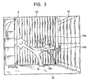
- Fig. 3 is a drawing showing a video-game screen.
- Fig. 4 is a block diagram showing the functional blocks of a central processing unit, and parts of the game system shown in Fig. 1.
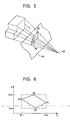
- Fig. 5 is a drawing illustrating coordinate transformation.
- Fig. 6 is a drawing illustrating determination of superimposition of polygons.
- Fig. 7 is a drawing illustrating superimposition of a character polygon and a projected polygon.
- Fig. 8 is a drawing illustrating superimposition of a character polygon and a projected polygon.
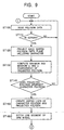
- Fig. 9 is a flowchart showing an example of a process for displaying a shadow.
- Fig. 10 is a flowchart showing an example of a process for displaying a shadow.
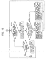
- Fig. 11 is a flowchart showing an example of -a process for displaying a shadow.
- Fig. 1 shows a game system 1 according to an embodiment of the present invention.
- the game system 1 includes a main unit, a television (TV) monitor 2 for outputting game images, an amplification circuit 3 and a speaker 4 for outputting game sound, and a recording medium 5 containing game data comprised of images, sound, and program data.
- the recording medium 5 is, for example, a so-called "read only memory (ROM) cassette" in which a ROM containing the game data and the program data of an operating system is accommodated in a plastic case, an optical disk, or a flexible disk.
- ROM read only memory
- a bus 7 comprised of an address bus, a data bus, and a control bus (not shown), is connected to a CPU 6.
- a random access memory (RAM) 8 interface (I/F) circuits 9 and 10, a signal processing processor 11, an image processor 12, and I/F circuits 13 and 14, are connected to the bus 7.
- a controller 16 is connected to the I/F circuit 10 via an operation-information I/F circuit 15.
- a digital-to-analog (D/A) converter 17 is connected to the I/F circuit 13, and a D/A converter 18 is connected to the I/F circuit 14.
- the RAM 8, the I/F circuit 9, and the recording medium 5 constitute a memory unit 19.
- the CPU 6, the signal processor 11, and the image processor 12 constitute a controller 20 for controlling the progress of the game.
- the I/F circuit 10, the operation-information I/F circuit 15, and the controller 16 constitute an operation input unit 21.
- the TV monitor 2, the I/F circuit 13, and the D/A converter 17 constitute an image display unit 22.
- the amplification circuit 3, the speaker 4, the I/F circuit 14, and the D/A converter 18 constitute a sound output unit 23.
- the signal processor 11 mainly performs computation in a three-dimensional space, computation for transformation from a position in a three-dimensional space into a position in a pseudo-three-dimensional space, illumination computation, and the generation and processing of sound data.
- the image processor 12 performs, based on a result of computation by the signal processor 11, the writing of image data to be rendered in the display area of the RAM 8, for example, the writing of texture data to an area of the RAM 8 that is specified by polygons.
- the writing of the texture data is described below.
- the controller 16 has a start button 16a, an A-button 16b, a B-button 16c, a cross key 16d, a control stick 16e, a left trigger button 16f, a right trigger button 16g, a C1-button 16h, a C2-button 16i, a C3-button 16j, a C4-button 16k, a connector 16m, and a depth trigger button 16n.
- a memory card or the like for temporarily storing the progress of the game can be set in the connector 16m.
- the form of the game system 1 differs depending on its purpose.
- the TV monitor 2, the amplification circuit 3, and the speaker 4 are provided separately from the main unit.
- all the components shown in Fig. 1 are integrated in a casing.
- the TV monitor 2 corresponds to a display for the computer or workstation
- the image processor 12 corresponds to part of the game program data recorded on the recording medium 5, or the hardware of an add-in board set in an add-in slot of the computer or workstation
- the I/F circuits 9, 10, 13, and 14, the D/A converters 17 and 18, and the operation-information I/F circuit 15, correspond to the hardware of an add-in board set in an add-in slot of the computer or workstation.
- the RAM 8 corresponds to the main memory of the computer or workstation, or to each area of an extension memory.
- the CPU 6 When the game system 1 is supplied with power by turning on a main-power switch (not shown), the CPU 6 reads, based on an operating system recorded on the recording medium 5, images, sound, and game-program data from the recording medium 5. A portion or the entirety of the images, sound, and game-program data read by the CPU 6 is stored in the RAM 8.
- the CPU 6 proceeds with the game, based on the game-program data stored in the RAM 8, and on instructions input through the controller 16 by a game player. In other words, the CPU 6 generates, based on instructions-from the--game player via the controller 16, commands as tasks for rendering and sound output.
- the signal processor 11 Based on the generated commands, the signal processor 11 performs computation of the position of a game character in a three-dimensional space (similarly in a two-dimensional space), illumination computation, and the generation and processing of sound data.
- the image processor 12 performs the writing of image data to be rendered in the display area of the RAM 8.
- the image data written in the RAM 8 are supplied to the D/A converter 17 via the I/F circuit 13.
- the supplied image data are converted into analog video signals by the D/A converter 17.
- the video signals are supplied to the TV monitor 2, and are displayed as an image on the screen of the TV monitor 2.
- the sound data output from the signal processor 11 are supplied to the D/A converter 18 via the I/F circuit 14.
- the supplied sound data are converted into analog sound signals, and are output as sound from the speaker 4 via the amplification circuit 3.
- the signal processor 11 performs computation based on commands from the CPU 6, and the image processor 12 performs, based on a result of the computation, the writing of image data to be rendered in the display area of the RAM 8.
- the RAM 8 has a non-display area and the display area (frame buffer).
- information recorded on the recording medium 5 such as polygon data, texture-selection data, and color data (texture data), are stored.
- the polygons are two-dimensional virtual polygonal figures constituting objects provided in the game space, that is, models and game characters.
- triangles and quadrangles are used as the polygons.
- the textures are two-dimensional images that are pasted on the polygons so that images are formed.
- the color data specify the colors of the textures.
- the polygon data which are coordinate data on vertexes constituting the polygons, and the texture-selection data, which select textures corresponding to the polygons, are stored to be integrated.
- Commands for rendering generated by the CPU 6, include commands that use polygons to render three-dimensional images, and commands for rendering ordinary two-dimensional images.
- Each command that uses polygons to render a three-dimensional image consists of a polygon-vertex-address data in the non-display area of the RAM 8; a texture-address data representing a position of the RAM 8 at which the texture data to be pasted on a polygon is stored; a color-address data representing a position in the display area of the RAM 8 at which the color data representing the color of a texture is stored; and a brightness data representing the brightness of the texture.
- the polygon-vertex-address data in the non-display area of the RAM 8 is replaced with a two-dimensional polygon-vertex-coordinate data by using the signal processor 11 to perform, based on moving-quantity_data and rotation-quantity data on a screen (viewpoint), coordinate transformation and the perspective projection transformation of polygon-vertex-coordinate data in a three-dimensional space from the CPU 6.
- the two-dimensional polygon-vertex-address data represents an address in the display area of the RAM 8.
- the image processor 12 writes a texture data represented by a pre-assigned texture-address data in a range of the display area of the RAM 8 which is represented by three or four polygon-vertex-address data. Thereby, objects expressed by pasting textures on polygons are displayed on the screen of the TV monitor 2.
- Figs. 2 and 3 show video game screens.
- a leading character 31 moves about as shown in Fig. 2.
- the leading character 31 is a graffito that came out from the body of a bus 32, and two-dimensionally consists of one polygon.
- a shadow 36 of the leading character 31, caused by light from a virtual light source, is displayed.
- the shadow 36 of the leading character 31 is displayed with its portion lost along the surface of the bus 32.
- a shadow 36a on the wall 33 as a background, a shadow 36b on the wall 34 perpendicular to the wall 33, and a shadow 36c on a ground 35 are displayed as shadows 36 of a leading character 31.
- Fig. 4 shows a functional block diagram of the CPU 6, and portions of the game system 1. In Fig. 4, components between the bus 7 and each block are not shown.
- the recording medium 5 contains a program for a game performed in a game space (virtual three-dimensional space).
- the program includes the coordinates of one polygon two-dimensionally constituting the leading character (Fig. 2), the coordinates of polygons three-dimensionally constituting the bus 32 (Fig. 2), and the walls 33 and 34, and the ground 35 (Fig. 3), and the coordinates of a virtual light source.
- the program includes textures indicating various postures of the leading character 31 as shown in Figs. 2 and 3, and textures indicating the respective background models.
- the program includes data representing shades, as data specifying the colors of the textures.
- the CPU 6 includes a projection means 61 and a color-data setting means 62.
- the projection means 61 includes a coordinate-transformation means 71, a superimposition determination means 72, a polygon-operation means 73, a texture operation means 74, and a coordinate inverse-transformation means 75, and performs processing for displaying game character shades.
- the coordinate-transformation means 71 projects each vertex of polygons constituting the background models (hereinafter referred to as "model polygons") onto a plane including polygons (hereinafter referred to as "character polygons") constituting the leading character 31.
- the projection is performed by finding the coordinates of points at which straight lines between the vertices of a polygon model 41 and a virtual source 42 intersect with a plane 44 including a character polygon 43.
- a polygon 45 consisting of the respective points is hereinafter referred to as a "projected polygon".
- the superimposition determination means 72 determines whether the projection polygon 45 (shown in Fig. 5) is superimposed on the character polygon 43 (shown in Fig. 5).
- the polygon-operation means 73 computes a vertex list of a common polygon formed by superimposition of the character polygon 43 and the projected polygon 45.
- the vertex list has coordinate data on the vertices of the common polygon, and data about the vertices.
- the common polygon is created by computing the vertex list. In this embodiment, the order of the common polygon is set to be clockwise.
- the texture operation means 74 computes differences between the vertices of the common polygon and the vertices of the character polygon 43, and computes, based on the differences, the texture coordinates of the common polygon.
- This processing is performed in order that in the texture indicating the leading character 31, only an area corresponding to the common polygon may be pasted onto an inversely projected polygon (described below). Thereby, the shadow 36 whose part is lost along the shape of the bus 32 can be displayed as shown in Fig. 2.
- the coordinate inverse-transformation means 75 obtains an inversely projected polygon by projecting the obtained polygon onto the plane of the original polygon.
- This projection is performed, similarly to the projection by the coordinate-transformation means 71, by finding the coordinates of points at which lines between the vertices of the common polygon and the virtual light source 42 intersect with a plane including the model polygon 41.
- the color-data setting means 62 sets, as texture-color data to be pasted onto the common polygon, color data (recorded on the recording medium 5) representing shade.
- the image processor 12 pastes a texture based on set texture coordinates onto an inversely projected polygon obtained by projecting the common polygon onto the plane of the original model polygon. At the same time, the image processor 12 writes a color data representing set shade in the display area of the RAM 8.
- shade For obtaining a texture-color data, by mixing the color data representing set shade and a color data on the background model at a predetermined ratio, and writing the obtained color data in the display area of the RAM 8, shade can be displayed with more virtual reality.
- Fig. 6 shows polygon superimposition determination.
- Figs. 7 and 8 show superimposition of the character polygon 43 and the projected polygon 45.
- Fig. 9 shows a process for displaying shade.
- step ST100 the coordinates of a model polygon, recorded on the recording medium 5, are read and stored in the RAM 8.
- step ST110 the process determines whether the model polygon is displayed in the screen of the TV monitor 2 when a set position is used as a viewpoint. If no model polygon is displayed in the screen of the monitor 2 ("NO" in step ST110), the process returns to step ST100, and the coordinates of a polygon constituting the next model are read.
- step ST110 If there are the coordinates of the read polygon in the screen of the TV monitor 2 ("YES" in step ST110), the vertices of the polygon are projected onto a plane including a character polygon, and the coordinates of points of intersection are computed (step ST 120).
- step ST130 maximum and minimum x- and y-coordinates of the projected polygon are computed.
- x max a maximum of x-coordinates
- x min a minimum of x-coordinates
- y max a maximum of y-coordinates
- y min a minimum of y-coordinates
- step ST140 the process determines whether the projected is superimposed onto the character polygon. In other words, by using the maximum and minimum x- and y-coordinates of the projected polygon and the character polygon, it is determined whether both polygons can be superimposed onto each other.
- a maximum of x-coordinates is represented by mx max
- a minimum of x-coordinates is represented by mx min
- a maximum of y-coordinates is represented by my max
- a minimum of y-coordinates is represented by my min
- a maximum of x-coordinates is represented by cx max
- a minimum of x-coordinates is represented by cx min
- a maximum of y-coordinates is represented by cy max
- a minimum of y-coordinates is represented by cy min , among the following inequalities: cx max ⁇ mx min ; cx min > mx max ; cy max ⁇ my min ; and cy min > my max ; one inequality is satisfied, the process determines that both polygons cannot be superimposed onto each other.
- step ST140 If both polygons cannot be superimposed ("NO" in step ST140), the process returns to step ST100.
- step ST140 If both polygons can be superimposed ("YES" in step ST140), a vertex list on the character polygon, and a vertex list on the projected polygon are created in step ST150.
- a vertex list on the character polygon 43 shown in Fig. 7 is represented by C0(Cvtx0)-C1(Cvtx1)-C2(Cvtx2)-C3(Cvtx3)-C0(Cvtx0)-....
- a vertex list on the polygon 45 shown in Fig. 7 is represented by M0(Mvtx0)-M1(Mvtx1)-M2(Mvtx2)-M3(Mvtx3)-M0(Mvtx0)-....
- Cvtx0, Cvtx1, Cvtx2, and Cvtx3 represent coordinate data on vertices C0, C1, C2, and C3, respectively
- Mvtx0, Mvtx1, Mvtx2, and Mvtx3 represent coordinate data on vertices M0, M1, M2, and M3, respectively.
- step ST160 (shown in Fig. 9), one line segment (hereinafter referred to as a "model line segment") forming one side of the projected polygon 45 is fetched.
- step ST170 by using, for example, a known flag-status determination technique, it is determined whether the model line segment intersects with each line segment (hereinafter referred to as a "character line segment") constituting the character polygon 43.
- step ST170 If both line segments do not intersect ("NO” in step ST170), the process proceeds to step ST180. If both line segments intersect ("YES" in step ST170), the coordinates of points at which both line segments intersect are computed in step ST190.
- step ST200 the process determines whether there is the initial point of the model line segment outside the character polygon 43. If there is not the initial point outside the character polygon 43 ("NO" in step ST200), the process proceeds to step ST230.
- step ST220 If, in step ST200, the initial point of the model line segment is outside the character polygon 43 ("YES" in step ST200), in step ST220, the coordinate data (in the vertex list of the projected polygon) on the initial point of the model segment having intersected are replaced by coordinate data on vertices of intersection, and the replaced coordinate data are combined with the vertex list on the character polygon 43.
- the process returns to step ST170, and it determines whether the model line segment intersects with another character segment.
- step ST230 the coordinate data (in the vertex list of the character polygon 43) on the initial point of the character line segment having intersected are replaced by coordinate data on vertices of intersection, and the replaced coordinate data are combined with the vertex list on the projected polygon.
- the process returns to step ST170, and it determines whether the model line segment intersects with another character segment.
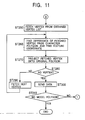
- step ST180 the process determines whether no model line segment to be fetched is detected. If a model line segment is detected ("NO” in step ST180), the next model line segment is fetched (step ST240) before the process returns to step ST170. If no model line segment is detected ("YES” in step ST180), the process proceeds to step ST250 (shown in Fig. 11).
- a coordinate data on vertex P0 of intersection is represented by Pvtx0
- a coordinate data on vertex P1 of intersection is represented by Pvtx1.
- step ST160 When model line segment M0M1 is fetched in step ST160, coordinate data Pvtx0 on vertex P0 of intersection is computed in step ST190 because the line segment intersects with character line segment C1C2. Since the terminal point M1 of the model line segment M0M1 is outside, the process proceeds from step ST200 to step ST230.
- step ST230 in the following vertex list on the character polygon 43: C0(Cvtx0)-C1(Cvtx1)-C2(Cvtx2)-C3(Cvtx3)-C0(Cvtx0)-..., a coordinate data on the initial point C1 of character line segment C1C2 having intersected is replaced by a coordinate data on vertex P0 of intersection.
- the vertex list on the character polygon 43 is expressed as follows: C0(Cvtx0)-C1(Pvtx0)-C2(Cvtx2)-C3(Cvtx3)-C0(Cvtx0)-....
- step ST240 model line segments M1M2 and M2M3 are fetched.
- the desired vertex list does not change since both line segments do not intersect with the character line segment ("NO" in step ST170).
- step ST240 When model line segment M3M0 is fetched in step ST240, coordinate data Pvtx1 on vertex P1 of intersection is computed in step ST190 because the line segment M3M0 intersects with character line segment C2C3.
- the initial point M3 of line segment M3M0 is outside the common polygon. Accordingly, the process proceeds from step ST200 to step ST220.
- step ST220 in the vertex list on the projected polygon 45, a coordinate data on the initial point M3 of line segment M3M0 having intersected is replaced by a coordinate data on vertex P1 of intersection.
- a vertex having a coordinate data on vertex P1 of intersection, that is, vertex M3, is combined with the initial point of line segment C2C3.
- This vertex list has coordinate data on the vertices of the common polygon (the shading portion shown in Fig. 7) formed by intersection of the character polygon 43 and the projected polygon 45, and data on the order of the vertices.
- Steps ST160 to ST240 for other superimposition of the character polygon 43 and the projected polygon 45 are described with reference to Fig. 8.
- a coordinate data on vertex Q0 of intersection is represented by Qvtx0
- a coordinate data on vertex Q1 of intersection is represented by Qvtx1.
- step ST160 When model line segment M0M1 is fetched in step ST160, the process determines negatively ("NO" in step ST170) since model line segment M0M1 does not intersect with the character polygon 43, and the next model line segment M1M2 is fetched. Since the fetched line segment M1M2 intersects with character line segment C0C1, in step ST190, coordinate data Qvtx0 on vertex Q0 of intersection is computed. The initial point M1 of model line segment M1M2 is outside the common polygon. Accordingly, the process proceeds from step ST200 to step ST220.
- step ST220 in the following vertex list on the projected polygon 45:
- step ST240 When model line segment M2M3 is fetched in step ST240, coordinate data Qvtx1 on vertex Q1 of intersection is computed in step ST190 because the fetched line segment intersects with character line segment C3C0.
- the end point M3 of model line segment M2M3 is outside the common polygon. Accordingly, the process proceeds from step ST210 to step ST230.
- step ST230 in the vertex list on the character polygon 43, the coordinate data on initial point C3, which is out of character line segment C3C0 is replaced, by the coordinate data on vertex Q1 of intersection.
- a vertex having the coordinate data on character polygon vertex Q1 of intersection, that is, vertex C3 is combined with initial point M2 inner than model line segment M2M3 having intersected.
- the obtained, desired vertex list has coordinate data on the vertices of the common polygon (the shading part shown in Fig. 8) formed by intersection of the character polygon 43 and the projected polygon 45, and data on the order of the vertices.
- step ST250 and the subsequent steps are described.
- step ST250 a vertex (e.g., vertex M0 in Fig. 7) is fetched from the obtained vertex list.
- step ST260 the difference between the fetched vertex and a reference vertex (e.g., vertex C0 in Fig. 7) of the character polygon 43 is found, and the texture coordinates of the fetched vertex are found based on the difference.
- the vertex is projected from a character-polygon-included plane onto the original polygon plane in step ST120, and the coordinates of a point of intersection is found in step ST270.
- step ST280 it is determined whether a vertex to be fetched has been detected. If a vertex to be fetched is detected ("NO" in step ST280), the next vertex (e.g., vertex P0 in Fig. 7) in the vertex list is fetched in step ST290, and the process returns to step ST260.
- a vertex to be fetched is detected ("NO" in step ST280)
- the next vertex e.g., vertex P0 in Fig. 7 in the vertex list is fetched in step ST290, and the process returns to step ST260.
- step ST280 If no vertex to be fetched is detected ("YES" in step ST280), data on the obtained vertex list, and the texture coordinate data are sent from the CPU 6 to the image processor 12 in step ST300.
- step ST310 it is determined whether a polygon model has been detected. If a polygon model has been detected ("NO” in step ST310), the process returns to step ST100 (shown in Fig. 9). If no polygon model has been detected ("YES” in step ST310), the process ends.
- the leading character 31 can be clearly displayed so as to be closer to a viewpoint than the background models, namely, the bus 32 (shown in Fig. 2) and the wooden walls 33 and 34 (shown in Fig. 3).
- the virtual reality of the shadow 36 can be enhanced.
- a common polygon By projecting a model polygon onto a plane including a character polygon so that a projected polygon is computed, and determining in a two-dimensional system whether the character polygon is superimposed on the projected polygon, a common polygon can be easily computed without an increase in computing load.
- the texture operation means 74 projects the superimposition polygon onto a plane including the character polygon, similarly to projection by the coordinate-transformation means 71 in the above-described embodiment.
- the texture operation means 74 computes differences between the coordinates of the projected polygon and the coordinates of the character polygon, and computes, based on the difference, the texture coordinates of the superimposition polygon.
Landscapes
- Engineering & Computer Science (AREA)
- Physics & Mathematics (AREA)
- Multimedia (AREA)
- General Physics & Mathematics (AREA)
- Computer Graphics (AREA)
- Theoretical Computer Science (AREA)
- Software Systems (AREA)
- Mathematical Analysis (AREA)
- Mathematical Physics (AREA)
- Geometry (AREA)
- Mathematical Optimization (AREA)
- Pure & Applied Mathematics (AREA)
- Algebra (AREA)
- Architecture (AREA)
- Computer Hardware Design (AREA)
- General Engineering & Computer Science (AREA)
- Image Generation (AREA)
- Processing Or Creating Images (AREA)
Claims (5)
- Bilderzeugungsvorrichtung zum Verwenden eines Blick- bzw. Gesichtspunkts bzw. Blickwinkels als einen Bezug, um das Bild eines Spielcharakters bzw. einer Spielfigur (31) und das Bild eines Modells hinter dem Spielcharakter (31) in einem virtuellen dreidimensionalen Raum zu erzeugen und um die Bilder auf Anzeigemitteln (2) anzuzeigen, wobei die Bilderzeugungsvorrichtung umfaßt:Modell-Polygon-Speichermittel (5) zum Speichern der Koordinaten von ModellPolygonen, die das Modellbild ausbilden bzw. darstellen;Charakter-Polygon-Speichermittel (5) zum Speichern der Koordinaten eines zweidimensionalen Charakter-Polygons, der das Charakterbild ausbildet;Modell-Textur-Speichermittel (5) zum Speichern einer Textur, die das Modellbild anzeigen;Charakter-Textur-Speichermittel (5) zum Speichern einer Textur, die das Charakterbild anzeigt;Lichtquellen-Speichermittel (5) zum Speichern der Koordinaten einer virtuellen Lichtquelle, die in dem dreidimensionalen Raum zur Verfügung gestellt ist; undProjektionsmittel (61) zum Berechnen der Form des Charakterpolygons, welches auf das Modellbild durch die virtuelle Lichtquelle projiziert ist;gekennzeichnet durch
Koordinaten-Transformationsmittel (71) zum Berechnen der Koordinaten eines projizierten Polygons, aufweisend Punkte, an welchen gerade Linien zwischen den Scheiteln von jedem Modellpolygon und der virtuellen Lichtquelle eine Ebene schneiden bzw. kreuzen, die das Charakterpolygon enthält;
Polygon-Betriebs- bzw. Betätigungsmittel (73) zum Berechnen der Koordinaten eines gemeinsamen Polygons, das durch eine Fläche bzw. einen Bereich ausgebildet ist, auf welcher(m) das projizierte Polygon dem Charakterpolygon überlagert ist;
Textur-Betätigungsmittel (74) zum Berechnen der Texturkoordinaten des gemeinsamen Polygons basierend auf Unterschieden zwischen den Koordinaten des Charakterpolygons und den Koordinaten des gemeinsamen Polygons; und
Koordinaten-Umkehrtransformationsmittel (75) zum Berechnen der Koordinaten eines invers projizierten Polygons bestehend aus Punkten, an welchen gerade Linien zwischen den Koordinaten des gemeinsamen Polygons und der virtuellen Lichtquelle eine Ebene schneiden bzw. kreuzen, welche das Modell-Polygon enthält; und
Farbdaten-Festlegungs- bzw. Setzmittel (62) zum Festlegen bzw. Setzen von Farbdaten auf dem umgekehrt projizierten Polygon, um den Schatten (36) darzustellen. - Bilderzeugungsvorrichtung nach Anspruch 1, wobei das Modellbild, das in den Modell-Polygon-Speichermitteln (5) gespeichert ist, eine Mehrzahl von dreidimensionalen Modellpolygonen als die Modellpolygone umfaßt.
- Bilderzeugungsvorrichtung nach einem der Ansprüche 1 oder 2, wobei die Farbdaten-Festlegungsmittel (62) als die Farbdaten, die den Schatten (36) des Charakters (31) darstellen, Daten verwenden, die durch ein Erhöhen der Konzentration von Farbdaten auf dem Texturbild erhalten sind, das in den Modelltextur-Speichermitteln gespeichert ist.
- Bilderzeugungsverfahren zum Verwenden eines Blick- bzw. Gesichtspunkts bzw. Blickwinkels als einen Bezug, um das Bild eines Spielcharakters bzw. einer Spielfigur (31) und das Bild eines Modells hinter dem Spielcharakter in einem virtuellen dreidimensionalen Raum zu erzeugen, und um die Bilder auf Anzeigemitteln (2) anzuzeigen, wobei das Bilderzeugungsverfahren die Schritte umfaßt:Speichern der Koordinaten von Modellpolygonen, die das Modellbild ausbilden bzw. darstellen;Speichern der Koordinaten eines zweidimensionalen Charakter-Polygons, das das Charakterbild ausbildet; undFinden bzw. Auffinden bzw. Ermitteln bzw. Erlangen der Form bzw. Gestalt des Charakterbilds als ein zweidimensionales Bild, welches auf das Modellbild als ein dreidimensionales Bild durch eine virtuelle Lichtquelle projiziert wird, die in dem virtuellen dreidimensionalen Raum zur Verfügung gestellt wird;gekennzeichnet durch
ein Berechnen der Koordinaten eines projizierten Polygons bestehend aus Punkten, an welchen gerade Linien zwischen den Scheiteln von jedem Modellpolygon und der virtuellen Lichtquelle eine Ebene schneiden bzw. kreuzen, die das Charakterpolygon enthält;
ein Berechnen der Koordinaten eines gemeinsamen Polygons, das durch einen Bereich ausgebildet wird, auf welchem das projizierte Polygon dem Charakterpolygon überlagert wird;
ein Berechnen der Texturkoordinaten des gemeinsamen Polygons basierend auf Unterschieden zwischen den Koordinaten des Charakterpolygons und den Koordinaten des gemeinsamen Polygons; und
ein Berechnen der Koordinaten eines umgekehrt projizierten Polygons aufweisend Punkte, an welchen gerade Linien zwischen den Koordinaten des gemeinsamen Polygons und der virtuellen Lichtquelle eine Ebene schneiden bzw. kreuzen, die das Modellpolygon enthält; und
Festlegen bzw. Setzen von Farbdaten auf dem umgekehrt projizierten Polygon, um den Schatten (36) darzustellen. - Computer-lesbares Aufzeichnungsmedium, enthaltend ein Bilderzeugungsprogramm zum Verwenden eines Blick- bzw. Gesichtspunkts bzw. Blickwinkels als einen Bezug, um das Bild eines Spielcharakters bzw. einer Spielfigur (31) und das Bild eines Modells hinter dem Spielcharakter in einem virtuellen dreidimensionalen Raum zu erzeugen, und um die Bilder auf Anzeigemitteln (2) anzuzeigen, wobei das Bilderzeugungsprogramm umfaßt
ein Speichern der Koordinaten von Modellpolygonen, die das Modellbild ausbilden bzw. darstellen;
ein Speichern der Koordinaten eines zweidimensionalen Charakterpolygons, das das Charakterbild ausbildet; und
einen Schritt zum Finden der Form bzw. Gestalt des Charakterbilds als ein zweidimensionales Bild, welches auf das Modellbild als ein dreidimensionales Bild durch eine virtuelle Lichtquelle projiziert wird, die in dem virtuellen dreidimensionalen Raum zur Verfügung gestellt wird;
gekennzeichnet durch
ein Berechnen der Koordinaten eines projizierten Polygons aufweisend Punkte, an welchen gerade Linien zwischen den Scheiteln von jedem Modellpolygon und der virtuellen Lichtquelle eine Ebene schneiden bzw. kreuzen, die das Charakterpolygon enthält;
ein Berechnen der Koordinaten eines gemeinsamen Polygons, das durch einen Bereich ausgebildet wird, auf welchem das projizierte Polygon dem Charakterpolygon überlagert wird;
ein Berechnen der Texturkoordinaten des gemeinsamen Polygons basierend auf Unterschieden zwischen den Koordinaten des Charakterpolygons und den Koordinaten des gemeinsamen Polygons; und
ein Berechnen der Koordinaten eines umgekehrt projizierten Polygons bestehend aus Punkten, an welchen gerade Linien zwischen den Koordinaten des gemeinsamen Polygons und der virtuellen Lichtquelle eine Ebene schneiden bzw. kreuzen, die das Modellpolygon enthält; und
Festlegen bzw. Setzen von Farbdaten auf dem umgekehrt projizierten Polygon, um den Schatten (36) darzustellen.
Applications Claiming Priority (2)
| Application Number | Priority Date | Filing Date | Title |
|---|---|---|---|
| JP10071063A JP2976963B2 (ja) | 1998-03-19 | 1998-03-19 | 画像作成装置、画像作成方法、画像作成プログラムが記録された可読記録媒体およびビデオゲーム装置 |
| JP7106398 | 1998-03-19 |
Publications (3)
| Publication Number | Publication Date |
|---|---|
| EP0948978A2 EP0948978A2 (de) | 1999-10-13 |
| EP0948978A3 EP0948978A3 (de) | 2001-04-18 |
| EP0948978B1 true EP0948978B1 (de) | 2006-10-04 |
Family
ID=13449705
Family Applications (1)
| Application Number | Title | Priority Date | Filing Date |
|---|---|---|---|
| EP99104074A Expired - Lifetime EP0948978B1 (de) | 1998-03-19 | 1999-03-18 | Bilderzeugungsvorrichtung, Bilderzeugungsverfahren und computerlesbares Aufzeichnungsmedium für Bilderzeugungsprogramm |
Country Status (6)
| Country | Link |
|---|---|
| EP (1) | EP0948978B1 (de) |
| JP (1) | JP2976963B2 (de) |
| KR (1) | KR100647861B1 (de) |
| CN (1) | CN1129872C (de) |
| DE (1) | DE69933406T2 (de) |
| TW (1) | TW457110B (de) |
Families Citing this family (11)
| Publication number | Priority date | Publication date | Assignee | Title |
|---|---|---|---|---|
| JP3599268B2 (ja) * | 1999-03-08 | 2004-12-08 | 株式会社ソニー・コンピュータエンタテインメント | 画像処理方法、画像処理装置及び記録媒体 |
| JP3369159B2 (ja) | 2000-02-17 | 2003-01-20 | 株式会社ソニー・コンピュータエンタテインメント | 画像描画方法、画像描画装置、記録媒体及びプログラム |
| JP3641578B2 (ja) | 2000-08-31 | 2005-04-20 | コナミ株式会社 | ゲーム用3次元画像処理方法、装置、ゲーム用3次元画像処理プログラムを記録したコンピュータ読み取り可能な記録媒体及びビデオゲーム装置 |
| JP2002222436A (ja) * | 2000-11-22 | 2002-08-09 | Sony Computer Entertainment Inc | オブジェクト制御方法、コンピュータに実行させるためのオブジェクト制御処理プログラム、コンピュータに実行させるためのオブジェクト制御処理プログラムを記録したコンピュータ読み取り可能な記録媒体、オブジェクト制御処理プログラムを実行するプログラム実行装置 |
| US6924798B2 (en) * | 2001-05-22 | 2005-08-02 | Intel Corporation | Real-time multi-resolution shadows |
| JP4065507B2 (ja) * | 2002-07-31 | 2008-03-26 | キヤノン株式会社 | 情報提示装置および情報処理方法 |
| JP2004246877A (ja) * | 2003-01-24 | 2004-09-02 | Sega Corp | ゲームのキャラクタに画像を投影するプログラム、そのプログラムが組み込まれたゲーム機、及びそのプログラムが格納された記録媒体 |
| KR20080080640A (ko) * | 2005-12-16 | 2008-09-04 | 코닌클리케 필립스 일렉트로닉스 엔.브이. | 쉐도우 생성 장치 및 방법 |
| JP4612031B2 (ja) * | 2007-09-28 | 2011-01-12 | 株式会社コナミデジタルエンタテインメント | 画像生成装置、画像生成方法、ならびに、プログラム |
| JP4852555B2 (ja) * | 2008-01-11 | 2012-01-11 | 株式会社コナミデジタルエンタテインメント | 画像処理装置、画像処理方法、ならびに、プログラム |
| US10126880B2 (en) | 2013-08-22 | 2018-11-13 | Hewlett-Packard Development Company, L.P. | Projective computing system |
Family Cites Families (5)
| Publication number | Priority date | Publication date | Assignee | Title |
|---|---|---|---|---|
| JPS58121091A (ja) * | 1982-01-14 | 1983-07-19 | 池上通信機株式会社 | 立体感表示方式 |
| US5415549A (en) * | 1991-03-21 | 1995-05-16 | Atari Games Corporation | Method for coloring a polygon on a video display |
| JP3442181B2 (ja) * | 1995-02-17 | 2003-09-02 | 株式会社ナムコ | 3次元ゲーム装置及び画像合成方法 |
| JP3667393B2 (ja) * | 1995-08-04 | 2005-07-06 | 株式会社ナムコ | 3次元ゲーム装置及び画像合成方法 |
| US6157733A (en) * | 1997-04-18 | 2000-12-05 | At&T Corp. | Integration of monocular cues to improve depth perception |
-
1998
- 1998-03-19 JP JP10071063A patent/JP2976963B2/ja not_active Expired - Fee Related
-
1999
- 1999-02-11 KR KR1019990004788A patent/KR100647861B1/ko not_active Expired - Fee Related
- 1999-03-16 TW TW088104037A patent/TW457110B/zh not_active IP Right Cessation
- 1999-03-18 DE DE69933406T patent/DE69933406T2/de not_active Expired - Lifetime
- 1999-03-18 EP EP99104074A patent/EP0948978B1/de not_active Expired - Lifetime
- 1999-03-19 CN CN99103069A patent/CN1129872C/zh not_active Expired - Fee Related
Non-Patent Citations (2)
| Title |
|---|
| ATHERTON P. ET AL: "Polygon Shadow Generation", PROC. INT. CONF. ON COMPUTER GRAPHICS AND INTERACTIVE TECHNIQUES, vol. 12, August 1978 (1978-08-01), pages 275 - 281 * |
| BOUKNIGHT W.J.: "A Procedure for Generation of Three-dimensional Half-toned Computer Graphics Presentations", COMMUNICATIONS OF THE ACM, vol. 13, no. 9, September 1970 (1970-09-01), pages 527 - 536 * |
Also Published As
| Publication number | Publication date |
|---|---|
| KR19990077421A (ko) | 1999-10-25 |
| EP0948978A3 (de) | 2001-04-18 |
| CN1129872C (zh) | 2003-12-03 |
| KR100647861B1 (ko) | 2006-11-24 |
| JP2976963B2 (ja) | 1999-11-10 |
| JPH11272882A (ja) | 1999-10-08 |
| DE69933406T2 (de) | 2007-08-16 |
| TW457110B (en) | 2001-10-01 |
| CN1231460A (zh) | 1999-10-13 |
| HK1022443A1 (en) | 2000-08-11 |
| DE69933406D1 (de) | 2006-11-16 |
| EP0948978A2 (de) | 1999-10-13 |
Similar Documents
| Publication | Publication Date | Title |
|---|---|---|
| JP3637031B2 (ja) | ゲーム装置およびゲームプログラム | |
| JP3668019B2 (ja) | 記録媒体、画像処理装置および画像処理方法 | |
| EP0990458B1 (de) | Videospielvorrichtung, Verfahren zum Umschalten der Blickpunktlage auf einem Bildschirm eines Videospiels, und Aufzeichnungsmedium für Blickpunktlageumschaltungs-Videospielprogramm | |
| US7104891B2 (en) | Game machine and game program for displaying a first object casting a shadow formed by light from a light source on a second object on a virtual game space | |
| US6878065B2 (en) | Video game system, character action control method, and readable storage medium storing character action control program | |
| JP2004329463A (ja) | ゲーム装置および仮想カメラの制御プログラム | |
| US6897865B2 (en) | Three-dimensional image processing method and apparatus, readable storage medium storing three-dimensional image processing program and video game system | |
| EP0992267B1 (de) | Bilderzeugungsgerät, Verfahren zum Umschalten zwischen dargestellten Szenen für das Bilderzeugungsgerät, computerlesbares Aufzeichnungsmedium mit einem Programm zum Umschalten zwischen dargestellten Szenen und Videospielvorrichtung | |
| EP0948978B1 (de) | Bilderzeugungsvorrichtung, Bilderzeugungsverfahren und computerlesbares Aufzeichnungsmedium für Bilderzeugungsprogramm | |
| US6781592B2 (en) | Image generating device, image generating method, readable storage medium storing image generating program, and video game device | |
| JP4833674B2 (ja) | ゲーム装置、ゲーム装置の制御方法及びプログラム | |
| US6326967B1 (en) | Image creating apparatus, image creating method, and computer-readable recording medium containing image creating program | |
| JP3926828B1 (ja) | ゲーム装置、ゲーム装置の制御方法及びプログラム | |
| JP3602835B2 (ja) | ビデオゲーム装置およびその制御方法ならびにゲームプログラム | |
| JP3001538B1 (ja) | ビデオゲーム装置、ビデオゲームにおけるモデル表示方法及びビデオゲームにおけるモデル表示プログラムが記録された可読記録媒体 | |
| US7245298B2 (en) | Game system, image drawing method for game system, and computer-readable storage medium storing game program | |
| JP3839355B2 (ja) | ゲーム装置およびゲームプログラム | |
| HK1022443B (en) | Image creating apparatus, image creating method, and computer-readable recording medium containing image creating program | |
| JP4219766B2 (ja) | 画像生成プログラムおよび画像生成装置 | |
| HK1022444B (en) | Image creating apparatus, image creating method, and computer-readable recording medium containing image creating program | |
| HK1059234B (en) | Video game apparatus and control method thereof |
Legal Events
| Date | Code | Title | Description |
|---|---|---|---|
| PUAI | Public reference made under article 153(3) epc to a published international application that has entered the european phase |
Free format text: ORIGINAL CODE: 0009012 |
|
| AK | Designated contracting states |
Kind code of ref document: A2 Designated state(s): DE FR GB |
|
| AX | Request for extension of the european patent |
Free format text: AL;LT;LV;MK;RO;SI |
|
| PUAL | Search report despatched |
Free format text: ORIGINAL CODE: 0009013 |
|
| AK | Designated contracting states |
Kind code of ref document: A3 Designated state(s): AT BE CH CY DE DK ES FI FR GB GR IE IT LI LU MC NL PT SE |
|
| AX | Request for extension of the european patent |
Free format text: AL;LT;LV;MK;RO;SI |
|
| RIC1 | Information provided on ipc code assigned before grant |
Free format text: 7A 63F 9/22 A, 7G 06T 15/50 B |
|
| 17P | Request for examination filed |
Effective date: 20010628 |
|
| AKX | Designation fees paid |
Free format text: DE FR GB |
|
| 17Q | First examination report despatched |
Effective date: 20040203 |
|
| GRAP | Despatch of communication of intention to grant a patent |
Free format text: ORIGINAL CODE: EPIDOSNIGR1 |
|
| RIC1 | Information provided on ipc code assigned before grant |
Ipc: 7G 06T 15/50 B Ipc: 7A 63F 13/00 A |
|
| GRAS | Grant fee paid |
Free format text: ORIGINAL CODE: EPIDOSNIGR3 |
|
| GRAA | (expected) grant |
Free format text: ORIGINAL CODE: 0009210 |
|
| AK | Designated contracting states |
Kind code of ref document: B1 Designated state(s): DE FR GB |
|
| REG | Reference to a national code |
Ref country code: GB Ref legal event code: FG4D |
|
| REF | Corresponds to: |
Ref document number: 69933406 Country of ref document: DE Date of ref document: 20061116 Kind code of ref document: P |
|
| REG | Reference to a national code |
Ref country code: HK Ref legal event code: GR Ref document number: 1022443 Country of ref document: HK |
|
| ET | Fr: translation filed | ||
| PLBE | No opposition filed within time limit |
Free format text: ORIGINAL CODE: 0009261 |
|
| STAA | Information on the status of an ep patent application or granted ep patent |
Free format text: STATUS: NO OPPOSITION FILED WITHIN TIME LIMIT |
|
| 26N | No opposition filed |
Effective date: 20070705 |
|
| REG | Reference to a national code |
Ref country code: GB Ref legal event code: 732E Free format text: REGISTERED BETWEEN 20090514 AND 20090520 |
|
| REG | Reference to a national code |
Ref country code: FR Ref legal event code: TP Ref country code: FR Ref legal event code: CD Ref country code: FR Ref legal event code: CA |
|
| PGFP | Annual fee paid to national office [announced via postgrant information from national office to epo] |
Ref country code: DE Payment date: 20130321 Year of fee payment: 15 Ref country code: FR Payment date: 20130408 Year of fee payment: 15 Ref country code: GB Payment date: 20130321 Year of fee payment: 15 |
|
| REG | Reference to a national code |
Ref country code: DE Ref legal event code: R119 Ref document number: 69933406 Country of ref document: DE |
|
| GBPC | Gb: european patent ceased through non-payment of renewal fee |
Effective date: 20140318 |
|
| REG | Reference to a national code |
Ref country code: FR Ref legal event code: ST Effective date: 20141128 |
|
| REG | Reference to a national code |
Ref country code: DE Ref legal event code: R119 Ref document number: 69933406 Country of ref document: DE Effective date: 20141001 |
|
| PG25 | Lapsed in a contracting state [announced via postgrant information from national office to epo] |
Ref country code: GB Free format text: LAPSE BECAUSE OF NON-PAYMENT OF DUE FEES Effective date: 20140318 Ref country code: FR Free format text: LAPSE BECAUSE OF NON-PAYMENT OF DUE FEES Effective date: 20140331 Ref country code: DE Free format text: LAPSE BECAUSE OF NON-PAYMENT OF DUE FEES Effective date: 20141001 |