EP0949008B1 - Vorrichtung zum Beschichten von Blechen und Bändern - Google Patents
Vorrichtung zum Beschichten von Blechen und Bändern Download PDFInfo
- Publication number
- EP0949008B1 EP0949008B1 EP99250079A EP99250079A EP0949008B1 EP 0949008 B1 EP0949008 B1 EP 0949008B1 EP 99250079 A EP99250079 A EP 99250079A EP 99250079 A EP99250079 A EP 99250079A EP 0949008 B1 EP0949008 B1 EP 0949008B1
- Authority
- EP
- European Patent Office
- Prior art keywords
- pump
- feed pump
- main feed
- medium
- flow
- Prior art date
- Legal status (The legal status is an assumption and is not a legal conclusion. Google has not performed a legal analysis and makes no representation as to the accuracy of the status listed.)
- Expired - Lifetime
Links
- 239000011248 coating agent Substances 0.000 title claims abstract description 14
- 238000000576 coating method Methods 0.000 title claims abstract description 14
- 239000007921 spray Substances 0.000 claims abstract description 10
- 239000002184 metal Substances 0.000 claims description 4
- 230000001105 regulatory effect Effects 0.000 claims description 3
- 238000005507 spraying Methods 0.000 claims description 2
- 238000010992 reflux Methods 0.000 description 9
- 238000010586 diagram Methods 0.000 description 4
- 230000010349 pulsation Effects 0.000 description 3
- 230000007704 transition Effects 0.000 description 3
- 239000012530 fluid Substances 0.000 description 2
- 230000001133 acceleration Effects 0.000 description 1
- 238000010420 art technique Methods 0.000 description 1
- 239000003795 chemical substances by application Substances 0.000 description 1
- 230000001276 controlling effect Effects 0.000 description 1
- 238000007689 inspection Methods 0.000 description 1
- 238000009434 installation Methods 0.000 description 1
- 238000012423 maintenance Methods 0.000 description 1
- 238000005086 pumping Methods 0.000 description 1
Images

Classifications
-
- B—PERFORMING OPERATIONS; TRANSPORTING
- B67—OPENING, CLOSING OR CLEANING BOTTLES, JARS OR SIMILAR CONTAINERS; LIQUID HANDLING
- B67D—DISPENSING, DELIVERING OR TRANSFERRING LIQUIDS, NOT OTHERWISE PROVIDED FOR
- B67D7/00—Apparatus or devices for transferring liquids from bulk storage containers or reservoirs into vehicles or into portable containers, e.g. for retail sale purposes
- B67D7/06—Details or accessories
- B67D7/58—Arrangements of pumps
- B67D7/70—Arrangements of pumps of two or more pumps in series or parallel
-
- B—PERFORMING OPERATIONS; TRANSPORTING
- B05—SPRAYING OR ATOMISING IN GENERAL; APPLYING FLUENT MATERIALS TO SURFACES, IN GENERAL
- B05B—SPRAYING APPARATUS; ATOMISING APPARATUS; NOZZLES
- B05B9/00—Spraying apparatus for discharge of liquids or other fluent material, without essentially mixing with gas or vapour
- B05B9/03—Spraying apparatus for discharge of liquids or other fluent material, without essentially mixing with gas or vapour characterised by means for supplying liquid or other fluent material
- B05B9/04—Spraying apparatus for discharge of liquids or other fluent material, without essentially mixing with gas or vapour characterised by means for supplying liquid or other fluent material with pressurised or compressible container; with pump
- B05B9/0403—Spraying apparatus for discharge of liquids or other fluent material, without essentially mixing with gas or vapour characterised by means for supplying liquid or other fluent material with pressurised or compressible container; with pump with pumps for liquids or other fluent material
- B05B9/0406—Spraying apparatus for discharge of liquids or other fluent material, without essentially mixing with gas or vapour characterised by means for supplying liquid or other fluent material with pressurised or compressible container; with pump with pumps for liquids or other fluent material with several pumps
-
- F—MECHANICAL ENGINEERING; LIGHTING; HEATING; WEAPONS; BLASTING
- F04—POSITIVE - DISPLACEMENT MACHINES FOR LIQUIDS; PUMPS FOR LIQUIDS OR ELASTIC FLUIDS
- F04B—POSITIVE-DISPLACEMENT MACHINES FOR LIQUIDS; PUMPS
- F04B49/00—Control, e.g. of pump delivery, or pump pressure of, or safety measures for, machines, pumps, or pumping installations, not otherwise provided for, or of interest apart from, groups F04B1/00 - F04B47/00
- F04B49/007—Installations or systems with two or more pumps or pump cylinders, wherein the flow-path through the stages can be changed, e.g. from series to parallel
-
- F—MECHANICAL ENGINEERING; LIGHTING; HEATING; WEAPONS; BLASTING
- F04—POSITIVE - DISPLACEMENT MACHINES FOR LIQUIDS; PUMPS FOR LIQUIDS OR ELASTIC FLUIDS
- F04B—POSITIVE-DISPLACEMENT MACHINES FOR LIQUIDS; PUMPS
- F04B49/00—Control, e.g. of pump delivery, or pump pressure of, or safety measures for, machines, pumps, or pumping installations, not otherwise provided for, or of interest apart from, groups F04B1/00 - F04B47/00
- F04B49/22—Control, e.g. of pump delivery, or pump pressure of, or safety measures for, machines, pumps, or pumping installations, not otherwise provided for, or of interest apart from, groups F04B1/00 - F04B47/00 by means of valves
-
- F—MECHANICAL ENGINEERING; LIGHTING; HEATING; WEAPONS; BLASTING
- F04—POSITIVE - DISPLACEMENT MACHINES FOR LIQUIDS; PUMPS FOR LIQUIDS OR ELASTIC FLUIDS
- F04B—POSITIVE-DISPLACEMENT MACHINES FOR LIQUIDS; PUMPS
- F04B2203/00—Motor parameters
- F04B2203/02—Motor parameters of rotating electric motors
- F04B2203/0209—Rotational speed
-
- F—MECHANICAL ENGINEERING; LIGHTING; HEATING; WEAPONS; BLASTING
- F04—POSITIVE - DISPLACEMENT MACHINES FOR LIQUIDS; PUMPS FOR LIQUIDS OR ELASTIC FLUIDS
- F04B—POSITIVE-DISPLACEMENT MACHINES FOR LIQUIDS; PUMPS
- F04B2205/00—Fluid parameters
- F04B2205/09—Flow through the pump
Definitions
- the invention relates to a device for metered conveying a medium, the device a storage tank for the medium has, and that at least one main pump the Promote medium away from storage tank.
- a device for metered conveying a medium the device a storage tank for the medium has, and that at least one main pump the Promote medium away from storage tank.
- Each pump pair 4a, 4b and 5a, 5b is dimensioned so that the funded volume flow range can be covered.
- the smaller pump covers the range of small volume flows and the larger pump covers the volume range of the large volume flows.
- the areas of both pumps overlap, as shown in Figures 3 and 4, depending on the given requirements of different sizes.
- both pumps 4a, 4b do not run simultaneously. Only during the transition, during acceleration or braking of the sheets to be oiled, it comes in part to the simultaneous pumping of the pumps. For this short moment inaccuracies in the dosage are unavoidable.
- the requirements for the Control range of the pumps are higher with this concept (1: 200) as a concept with a smaller overlap area (1:40). Both concepts have in common that the whole Control range of the pump is utilized. This means that the pumps are also driven in the lower speed range, whereby pulsations of the volume flow occur.
- Object of the present invention is therefore, a To provide a device in which a pulsation of Volume flows in the widest possible control range be avoided.
- This object is inventively, according to the claims, achieved in that a defined part of the flow after leaving the Main feed pump back to the suction side of the main feed pump or the storage tank is passed, and to adjust the branched off flow at least one reflux pump serves.
- the object is for oil coating equipment, according to the claims, especially thereby solved that a defined part of the flow before the Reaching the means branched off and back to the suction side the main pump or storage tank is routed, and at least one to set the branched flow Return pump is arranged parallel to the main pump, the medium from the outlet side of the main pump to the suction side of the main pump or the storage tank promotes.
- the parallel connection of the main pump and the reflux pump these promote each other, it is possible to pump both pumps at the same speed which leaves no medium to the distributing means is encouraged.
- both pumps are not zero in speed must be driven to the maximum speed, since by the Subtraction of the two pumped volume flows of the pumps a minimum arbitrary speed is selectable, at the straight no medium is conveyed to the distribution means. This will be advantageous in the prior art occurring pulsations of the volume flows due to low speeds of the pump avoided.
- main conveyor and the Return flow pump By driving the main pump and the Return flow pump can effectively conveyed volume flow by means of only one drive or by means of only one manipulated variable be set.
- main conveyor and the Return flow pump for different volume flows be dimensioned the same speed.
- two identical pumps, with different ones Rotational speeds are operated to use, wherein the Main feed pump runs at a higher speed than the Reflux pump.
- the various speeds can be e.g. realize by means of differential or transfer case.
- the invention is based on Embodiments explained in more detail.
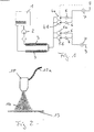
- FIG. 1 shows a device according to the prior art Technique with a storage tank 1, from which a pump 2 a medium, in particular oil, is conveyed through heated lines 3 back into the tank 1 passes. Between the heated lines 3 by means of pumps 4a, 4b, 5a, 5b, the oil pumped out and from there via each pump downstream check valves 6 to one in Figure 2 promoted shown electrostatic spray bar 10.
- a medium in particular oil
- FIG. 2 only one electrostatic spray bar 10 is shown for the coating of the top of the sheet 13 shown.
- the pumps 4a, 4b and the pumps 5a, 5b for the coating of the sheet 13 with a coating medium 14 are not shown pump controls controlled, with the actual flow rate each Pump pair by means of a flow meter 7, which in the Line 8, 9 to the respective electrostatic spray bar 10 is located, measured and the pump controls is supplied.
- the fluid enters the electrostatic spray bar and is there evenly over the width of the sheet metal strip 13 distributed.
- FIGS 3 and 4 show the overlapping areas of Feed pump pairs 4a, 4b and 5a, 5b in a device according to the prior art due to the Parallel connection and promotion in the same direction both pumps is the smallest flow through the limited minimum speed of the smallest of the two pumps.
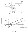
- FIG. 5 shows the device according to the invention, in which parallel to the main pump 16, a reflux pump 17th is arranged, with two pumps 16, 17 each one Check valve 6 is connected downstream, which is for generating a defined leakage current in the respective pump is used.
- the reflux pump 17 and the check valve 6 is over a multi-way valve 18 with the main feed pump 16 in Connection.
- the multi-way valve 18 can once the Return flow pump 17 in the opposite direction to Promote main feed pump.
- Multiway valve 18 the reflux pump 17 of the Main pump 16 to separate with two supply lines.
- the speed-controlled main pump 16 is in Dependence of the value of the flow meter 17a regulated.
- Two pumps can be used in parallel with the feed pump Proportional valves are arranged, the Check valve 6 arranged directly behind the feed pump is. Between the two proportional valves is then the Volume flow tapped by a line and the Guided spray bar. To control the two Proportional valves are also not shown Tachometer, which is arranged in the line. ever After setting the proportional valves, a specific Pressure and thus a certain flow in the line be adjusted, the speed of the feed pump is kept constant. However, it is also possible to use the pump speed controlled perform, with yet another Control range with the same dimensioning of Proportional valves is possible.
- the line 15 attacks, As shown in Figure 1, the fluid between the both heated lines 3 from.
- the pump B is operated at a constant speed, whereby it promotes a constant flow rate.
Landscapes
- Engineering & Computer Science (AREA)
- Mechanical Engineering (AREA)
- General Engineering & Computer Science (AREA)
- Coating Apparatus (AREA)
- Application Of Or Painting With Fluid Materials (AREA)
- Nozzles (AREA)
- Electrostatic Spraying Apparatus (AREA)
Description
Bei den herkömmlich bekannten Vorrichtungen, wie sie in den Figuren 1 bis 4 dargestellt sind, wird aus einem Vorratstank 1 über eine Pumpe 2 und einen Filter das beheizte Öl im Kreislauf über geheizte Leitungen 3 in dem Bereich der Einölmaschine und wieder zurück in den Tank geleitet. Um das Blech von oben und unten gleichmäßig mit Öl besprühen bzw. beschichten zu können, sind für die Ober- und Unterseite des Bleches jeweils zwei Dosierpumpen vorgesehen, die aus dem Kreislauf die erforderliche Ölmenge entnehmen. Zur genauen Dosierung wird die abgenommene Ölmenge durch ein Durchflußmeßgerät überwacht. Jedes Pumpenpaar 4a, 4b sowie 5a, 5b ist so dimensioniert, daß der geförderte Volumenstrombereich abgedeckt werden kann. Dabei deckt die kleinere Pumpe den Bereich der kleinen Volumenströme und die größere Pumpe den Volumenbereich der großen Volumenströme ab. Die Bereiche beider Pumpen überdecken sich, wie in den Figuren 3 und 4 dargestellt, je nach den gegebenen Anforderungen unterschiedlich groß. Im allgemeinen laufen beide Pumpen 4a, 4b nicht gleichzeitig. Lediglich beim Übergang, beim Beschleunigen oder Bremsen der zu beölenden Bleche kommt es teilweise zum gleichzeitigen Fördern der Pumpen. Für diesen kurzen Moment sind Ungenauigkeiten in der Dosierung unvermeidbar.
- Figur 1:
- ein Blockschaltbild einer Vorrichtung gemäß dem Stand der Technik;
- Figur 2:
- eine schematische Darstellung eines elektrostatischen Sprühbalkens zur Verteilung von Öl auf Blechen;
- Figur 3 und 4:
- Steuerungsbereiche von Förderpumpen gemäß dem Stand der Technik;
- Figur 5:
- ein Blockschaltbild mit zur Hauptförderpumpe parallel geschalteter Rückflußpumpe und
- Figur 6:
- ein Drehzahl-Volumenstrom-Diagramm für eine Vorrichtung gemäß der Figur 5;
Claims (11)
- Vorrichtung zum dosierten Fördern eines Mediums, wobei die Vorrichtung einen Vorratstank für das Medium hat, und mindestens eine Hauptförderpumpe das Medium vom Vorratstank weg fördert,
dadurch gekennzeichnet, daß ein definierter Teil des Förderstromes nach Verlassen der Hauptförderpumpe zurück zur Ansaugseite der Hauptförderpumpe oder dem Vorratstank geleitet wird, und zur Einstellung des abgezweigten Förderstromes mindestens eine Rückflußpumpe dient. - Vorrichtung zum Beschichten von Blechen und/oder Bändern (13) mit einem Medium (14), insbesondere Öl, wobei die Vorrichtung einen Vorratstank (1) für das Medium (14) und ein Mittel (10) zum Verteilen und/oder Versprühen des Mediums (14) auf die Bleche und/oder Bänder (13) hat, und daß mindestens eine Hauptförderpumpe (16) nach Bedarf eine bestimmte Menge des Mediums (14) vom Vorratstank (1) hin zu dem Mittel (10) fördert,
dadurch gekennzeichnet, daß ein definierter Teil des Förderstromes vor dem Erreichen des Mittels (10) abgezweigt und zurück zur Ansaugseite der Hauptförderpumpe (16) oder dem Vorratstank (1) geleitet wird, und zur Einstellung des abgezweigten Förderstromes mindestens eine Rückflußpumpe (17) parallel zur Hauptförderpumpe (16) angeordnet ist, die das Medium (14) von der Auslaßseite der Hauptförderpumpe (16) hin zur Ansaugseite der Hauptförderpumpe (16) oder dem Vorratstank (1) fördert. - Vorrichtung nach Anspruch 1 oder 2,
dadurch gekennzeichnet, daß die Hauptförderpumpe (16), die das Medium (14) in Richtung des Mittels (10) fördert, drehzahlgeregelt ist, wobei die Hauptförderpumpe (16) einen Förderstrom fördert, der jeweils um den konstanten Förderstrom der Rückflußpumpe (17) größer ist, als der für das Beschichten benötigte Förderstrom. - Vorrichtung nach Anspruch 1 oder 2,
dadurch gekennzeichnet, daß die Rückflußpumpe (17) drehzahlgeregelt ist, wobei diese einen Förderstrom fördert, der jeweils um den konstanten Förderstrom der Hauptförderpumpe (16), die das Medium (14) in Richtung des Mittels (10) fördert, kleiner ist, als der für das Beschichten benötigte Förderstrom. - Vorrichtung nach einem der vorherigen Ansprüche,
dadurch gekennzeichnet, daß jeder Pumpe (16,17) ein Rückschlagventil (6), eine Drossel und/oder ein sonstiges Mittel zur Erzeugung eines Druckes auf Pumpenauslaßseite nachgeschaltet ist. - Vorrichtung nach einem der Ansprüche 1 bis 5,
dadurch gekennzeichnet, daß mittels einer Ventilsteuerung (18) die Förderrichtung der Rückflußpumpe (17) umkehrbar ist, derart, daß sowohl die Hauptförderpumpe (16) als auch die Rückflußpumpe (17) das Medium (14) vom Vorratstank (1) hin zum Mittel (10) fördern - Vorrichtung nach einem Ansprüche 1 bis 6,
dadurch gekennzeichnet, daß die Verbindungsleitungen von der Hauptförderpumpe (16) hin zur Rückflußpumpe (17) mittels Ventilen (18) unterbrechbar sind. - Vorrichtung nach Anspruch 1 oder 2,
dadurch gekennzeichnet, daß eine Reihenschaltung aus mindestens zwei Ventilen (22,23), von denen mindestens ein Ventil ein Proportionalventil ist, parallel zur Hauptförderpumpe (20) angeordnet ist, und zwischen den beiden Ventilen (22,23) das Medium (14) abgegriffen und zum Mittel (10) geleitet wird. - Vorrichtung nach Anspruch 8,
dadurch gekennzeichnet, daß die Hauptförderpumpe (20) mit konstanter Drehzahl fördert und mittels der Ventile (22,23) der abgegriffene Volumenstrom einstellbar ist. - Vorrichtung nach einem der Ansprüche 1 bis 9,
dadurch gekennzeichnet, daß das Mittel (10) ein elektrostatischer Sprühbalken ist. - Vorrichtung nach einem der Ansprüche 1 bis 10,
dadurch gekennzeichnet, daß die Hauptförderpumpe und die Rückföderpumpe über einen gemeinsamen insbesondere regelbaren Antrieb und/oder über ein Differential- oder Verteilergetriebe angetrieben sind.
Applications Claiming Priority (2)
| Application Number | Priority Date | Filing Date | Title |
|---|---|---|---|
| DE19811400A DE19811400A1 (de) | 1998-03-16 | 1998-03-16 | Vorrichtung zum Beschichten von Blechen oder Bändern |
| DE19811400 | 1998-03-16 |
Publications (3)
| Publication Number | Publication Date |
|---|---|
| EP0949008A2 EP0949008A2 (de) | 1999-10-13 |
| EP0949008A3 EP0949008A3 (de) | 2004-06-23 |
| EP0949008B1 true EP0949008B1 (de) | 2005-10-26 |
Family
ID=7861086
Family Applications (1)
| Application Number | Title | Priority Date | Filing Date |
|---|---|---|---|
| EP99250079A Expired - Lifetime EP0949008B1 (de) | 1998-03-16 | 1999-03-16 | Vorrichtung zum Beschichten von Blechen und Bändern |
Country Status (3)
| Country | Link |
|---|---|
| EP (1) | EP0949008B1 (de) |
| AT (1) | ATE307675T1 (de) |
| DE (2) | DE19811400A1 (de) |
Families Citing this family (5)
| Publication number | Priority date | Publication date | Assignee | Title |
|---|---|---|---|---|
| DE10104635A1 (de) * | 2001-02-02 | 2002-10-02 | Joma Hydromechanic Gmbh | Verfahren zum Aufrechterhalten einer konstanten Ausgangsgröße einer Förderpumpe, z.B. ihres Fördervolumens, die von einer in ihrer Drehzahl variablen Antriebsvorrichtung angetrieben wird, sowie Vorrichtung zur Durchführung des Verfahrens |
| DE102009019564A1 (de) * | 2009-05-02 | 2010-11-11 | Voith Patent Gmbh | Pumpverfahren und Hydraulikpumpensystem |
| DE102011118836B4 (de) * | 2011-11-18 | 2014-11-06 | Thomas Magnete Gmbh | Doppelpumpenaggregat mit gegenläufigen Förderrichtungen und Verfahren zum Betrieb desselben |
| CN104369403A (zh) * | 2014-10-05 | 2015-02-25 | 赛轮集团股份有限公司 | 一种轮胎成型机刷汽油装置 |
| US10578005B2 (en) * | 2016-02-01 | 2020-03-03 | Ghsp, Inc. | Smart two-pump apparatus, control and method |
Family Cites Families (12)
| Publication number | Priority date | Publication date | Assignee | Title |
|---|---|---|---|---|
| DE1221575B (de) * | 1959-04-06 | 1966-07-21 | Grundstueckverwaltungsgesellsc | Anordnung zur Abgaberegelung einer Betankungsanlage, insbesondere fuer Flugfeldtankwagen |
| DE2618046A1 (de) * | 1976-04-24 | 1977-11-10 | Sven O I Jonsson | Verfahren und vorrichtung zur ausnutzung gespeicherter potentieller energie beim entladen von waren |
| DE3007116C2 (de) * | 1980-02-26 | 1986-11-20 | Walter Hofmann, Maschinenfabrik, 2084 Rellingen | Anordnung zur pulsationsfreien Förderung eines flüssigen Mediums |
| FR2551365B1 (fr) * | 1983-08-01 | 1986-03-28 | Lorraine Laminage | Dispositif pour huiler des toles en bande continue |
| DE3330665A1 (de) * | 1983-08-25 | 1985-03-14 | Weitmann & Konrad GmbH & Co KG, 7022 Leinfelden-Echterdingen | Vorrichtung zum bestaeuben bewegter gegenstaende, insbesondere flaechiger unterlagen |
| HU191726B (en) * | 1984-11-29 | 1987-03-30 | Energiagazdalkodasi Intezet | Connection arrangement of damping dashpot |
| DE3713156A1 (de) * | 1986-04-18 | 1987-10-29 | Duma Konstruktionsbuero | Verfahren zum oelauftrag auf metallbaender |
| DE3639122A1 (de) * | 1986-11-15 | 1987-11-19 | Mtu Friedrichshafen Gmbh | Pumpenanordnung |
| JP2776882B2 (ja) * | 1989-04-27 | 1998-07-16 | 株式会社ユニシアジェックス | ポンプ装置 |
| DE4011846A1 (de) * | 1990-04-12 | 1991-10-17 | Bosch Gmbh Robert | Aggregat zum foerdern von kraftstoff |
| US5058805A (en) * | 1990-07-12 | 1991-10-22 | Brunswick Corporation | Paint spraying system |
| DE4432263C2 (de) * | 1994-09-10 | 1996-07-11 | Walterscheid Gmbh Gkn | Kombinationsventil für sauggedrosselte Hydraulikpumpen |
-
1998
- 1998-03-16 DE DE19811400A patent/DE19811400A1/de not_active Withdrawn
-
1999
- 1999-03-16 EP EP99250079A patent/EP0949008B1/de not_active Expired - Lifetime
- 1999-03-16 DE DE59912694T patent/DE59912694D1/de not_active Expired - Fee Related
- 1999-03-16 AT AT99250079T patent/ATE307675T1/de not_active IP Right Cessation
Also Published As
| Publication number | Publication date |
|---|---|
| DE19811400A1 (de) | 1999-09-23 |
| EP0949008A3 (de) | 2004-06-23 |
| DE59912694D1 (de) | 2005-12-01 |
| ATE307675T1 (de) | 2005-11-15 |
| EP0949008A2 (de) | 1999-10-13 |
Similar Documents
| Publication | Publication Date | Title |
|---|---|---|
| EP0463007B1 (de) | Gerät zum applizieren von pflanzenbehandlungsmitteln | |
| EP1317624B1 (de) | Hydraulisches system mit einer hauptpumpe und einer vordruckpumpe | |
| EP3957404B1 (de) | Applikationssystem zum beschichten von bauteilen und beschichtungseinrichtung | |
| DE10246946B4 (de) | Einrichtung zum Beschichten von Bedruckstoffen in einer Druckmaschine | |
| DE112013004977B4 (de) | Hydraulisches Antriebssystem und Verfahren zum Antrieb eines Bandförderers | |
| DE102010055019A1 (de) | Vorrichtung zum intermittierenden Auftragen eines flüssigen bis pastösen Mediums auf eine Auftragfläche | |
| DE3639245A1 (de) | In form einer schleife angeordnetes einspritz-zirkulations-system | |
| DE2435710B2 (de) | Vorrichtung zum Anpassen des Druckes einer Flüssigkeitsströmung an ihre Durchflußmenge | |
| EP1356206B1 (de) | Verfahren zum aufrechterhalten einer konstanten ausgangsgrösse einer förderpumpe, z.b. ihres fördervolumens, die von einer in ihrer drehzahl variablen antriebsvorrichtung angetrieben wird, sowie vorrichtung zur durchführung des verfahrens | |
| EP0949008A2 (de) | Vorrichtung zum Beschichten von Blechen und Bändern | |
| DE2508119B1 (de) | Verfahren und vorrichtung zum dosieren des leimauftrages auf eine laufende bahn, insbesondere wellpappenbahn | |
| DE2145130A1 (de) | Vorrichtung zum Einölen eines band- oder tafelförmigen Bleches | |
| DE3639122A1 (de) | Pumpenanordnung | |
| DE102007028096B3 (de) | Vorrichtung zum Auftragen eines Auftragmittels auf ein Substrat | |
| DE4035091A1 (de) | Auftragsvorrichtung | |
| EP0440845B1 (de) | Zapfvorrichtung zur Ausgabe flüssiger Kraftstoffe | |
| WO2015055610A1 (de) | DOSIEREINRICHTUNG ZUM DOSIEREN UND FÖRDERN EINES FLIEßFÄHIGEN SCHMIERMITTELS | |
| DE69810186T2 (de) | Mischvorrichtung zum Spritzen einer flüssigen Mischung | |
| DE3490138C2 (de) | Anlage zur Enteisung | |
| WO2007045589A1 (de) | Vorrichtung zum flächigen auftrag eines 2-komponenten materials auf einen träger | |
| DE102010016412A1 (de) | Vorrichtungsmodul zum Austragen von Schmiermittel aus einer Düse | |
| EP0060373B1 (de) | Vorrichtung zum Einölen band- oder tafelförmiger Bleche | |
| DE602004001344T2 (de) | Verfahren zum zuführen eines behandlungsmittels in eine auftragungsvorrichtung | |
| DE4227716C2 (de) | Ölzuführeinrichtung für eine Brennerspeiseeinrichtung | |
| DE2404711C3 (de) |
Legal Events
| Date | Code | Title | Description |
|---|---|---|---|
| PUAI | Public reference made under article 153(3) epc to a published international application that has entered the european phase |
Free format text: ORIGINAL CODE: 0009012 |
|
| AK | Designated contracting states |
Kind code of ref document: A2 Designated state(s): AT BE CH CY DE DK ES FI FR GB GR IE IT LI LU MC NL PT SE |
|
| AX | Request for extension of the european patent |
Free format text: AL;LT;LV;MK;RO;SI |
|
| PUAL | Search report despatched |
Free format text: ORIGINAL CODE: 0009013 |
|
| AK | Designated contracting states |
Kind code of ref document: A3 Designated state(s): AT BE CH CY DE DK ES FI FR GB GR IE IT LI LU MC NL PT SE |
|
| AX | Request for extension of the european patent |
Extension state: AL LT LV MK RO SI |
|
| RIC1 | Information provided on ipc code assigned before grant |
Ipc: 7F 23D 11/30 B Ipc: 7F 23D 11/28 B Ipc: 7F 23D 11/26 B Ipc: 7F 04B 49/24 B Ipc: 7F 04B 49/00 B Ipc: 7B 05B 9/04 A |
|
| 17P | Request for examination filed |
Effective date: 20041213 |
|
| GRAP | Despatch of communication of intention to grant a patent |
Free format text: ORIGINAL CODE: EPIDOSNIGR1 |
|
| AKX | Designation fees paid |
Designated state(s): AT BE CH DE DK ES FI FR GB GR IE IT LI LU MC NL PT SE |
|
| GRAS | Grant fee paid |
Free format text: ORIGINAL CODE: EPIDOSNIGR3 |
|
| GRAA | (expected) grant |
Free format text: ORIGINAL CODE: 0009210 |
|
| AK | Designated contracting states |
Kind code of ref document: B1 Designated state(s): AT BE CH DE DK ES FI FR GB GR IE IT LI LU MC NL PT SE |
|
| PG25 | Lapsed in a contracting state [announced via postgrant information from national office to epo] |
Ref country code: NL Free format text: LAPSE BECAUSE OF FAILURE TO SUBMIT A TRANSLATION OF THE DESCRIPTION OR TO PAY THE FEE WITHIN THE PRESCRIBED TIME-LIMIT Effective date: 20051026 Ref country code: IT Free format text: LAPSE BECAUSE OF FAILURE TO SUBMIT A TRANSLATION OF THE DESCRIPTION OR TO PAY THE FEE WITHIN THE PRESCRIBED TIME-LIMIT;WARNING: LAPSES OF ITALIAN PATENTS WITH EFFECTIVE DATE BEFORE 2007 MAY HAVE OCCURRED AT ANY TIME BEFORE 2007. THE CORRECT EFFECTIVE DATE MAY BE DIFFERENT FROM THE ONE RECORDED. Effective date: 20051026 Ref country code: IE Free format text: LAPSE BECAUSE OF FAILURE TO SUBMIT A TRANSLATION OF THE DESCRIPTION OR TO PAY THE FEE WITHIN THE PRESCRIBED TIME-LIMIT Effective date: 20051026 Ref country code: GB Free format text: LAPSE BECAUSE OF FAILURE TO SUBMIT A TRANSLATION OF THE DESCRIPTION OR TO PAY THE FEE WITHIN THE PRESCRIBED TIME-LIMIT Effective date: 20051026 Ref country code: FI Free format text: LAPSE BECAUSE OF FAILURE TO SUBMIT A TRANSLATION OF THE DESCRIPTION OR TO PAY THE FEE WITHIN THE PRESCRIBED TIME-LIMIT Effective date: 20051026 |
|
| REG | Reference to a national code |
Ref country code: GB Ref legal event code: FG4D Free format text: NOT ENGLISH |
|
| REG | Reference to a national code |
Ref country code: CH Ref legal event code: EP |
|
| REG | Reference to a national code |
Ref country code: IE Ref legal event code: FG4D Free format text: LANGUAGE OF EP DOCUMENT: GERMAN |
|
| REF | Corresponds to: |
Ref document number: 59912694 Country of ref document: DE Date of ref document: 20051201 Kind code of ref document: P |
|
| PG25 | Lapsed in a contracting state [announced via postgrant information from national office to epo] |
Ref country code: SE Free format text: LAPSE BECAUSE OF FAILURE TO SUBMIT A TRANSLATION OF THE DESCRIPTION OR TO PAY THE FEE WITHIN THE PRESCRIBED TIME-LIMIT Effective date: 20060126 Ref country code: GR Free format text: LAPSE BECAUSE OF FAILURE TO SUBMIT A TRANSLATION OF THE DESCRIPTION OR TO PAY THE FEE WITHIN THE PRESCRIBED TIME-LIMIT Effective date: 20060126 Ref country code: DK Free format text: LAPSE BECAUSE OF FAILURE TO SUBMIT A TRANSLATION OF THE DESCRIPTION OR TO PAY THE FEE WITHIN THE PRESCRIBED TIME-LIMIT Effective date: 20060126 |
|
| PG25 | Lapsed in a contracting state [announced via postgrant information from national office to epo] |
Ref country code: ES Free format text: LAPSE BECAUSE OF FAILURE TO SUBMIT A TRANSLATION OF THE DESCRIPTION OR TO PAY THE FEE WITHIN THE PRESCRIBED TIME-LIMIT Effective date: 20060206 |
|
| PG25 | Lapsed in a contracting state [announced via postgrant information from national office to epo] |
Ref country code: AT Free format text: LAPSE BECAUSE OF NON-PAYMENT OF DUE FEES Effective date: 20060316 |
|
| PG25 | Lapsed in a contracting state [announced via postgrant information from national office to epo] |
Ref country code: PT Free format text: LAPSE BECAUSE OF FAILURE TO SUBMIT A TRANSLATION OF THE DESCRIPTION OR TO PAY THE FEE WITHIN THE PRESCRIBED TIME-LIMIT Effective date: 20060327 |
|
| PG25 | Lapsed in a contracting state [announced via postgrant information from national office to epo] |
Ref country code: MC Free format text: LAPSE BECAUSE OF NON-PAYMENT OF DUE FEES Effective date: 20060331 Ref country code: LU Free format text: LAPSE BECAUSE OF NON-PAYMENT OF DUE FEES Effective date: 20060331 Ref country code: LI Free format text: LAPSE BECAUSE OF NON-PAYMENT OF DUE FEES Effective date: 20060331 Ref country code: CH Free format text: LAPSE BECAUSE OF NON-PAYMENT OF DUE FEES Effective date: 20060331 Ref country code: BE Free format text: LAPSE BECAUSE OF NON-PAYMENT OF DUE FEES Effective date: 20060331 |
|
| NLV1 | Nl: lapsed or annulled due to failure to fulfill the requirements of art. 29p and 29m of the patents act | ||
| REG | Reference to a national code |
Ref country code: IE Ref legal event code: FD4D |
|
| GBV | Gb: ep patent (uk) treated as always having been void in accordance with gb section 77(7)/1977 [no translation filed] |
Effective date: 20051026 |
|
| PLBE | No opposition filed within time limit |
Free format text: ORIGINAL CODE: 0009261 |
|
| STAA | Information on the status of an ep patent application or granted ep patent |
Free format text: STATUS: NO OPPOSITION FILED WITHIN TIME LIMIT |
|
| PG25 | Lapsed in a contracting state [announced via postgrant information from national office to epo] |
Ref country code: DE Free format text: LAPSE BECAUSE OF NON-PAYMENT OF DUE FEES Effective date: 20061003 |
|
| 26N | No opposition filed |
Effective date: 20060727 |
|
| REG | Reference to a national code |
Ref country code: CH Ref legal event code: PL |
|
| EN | Fr: translation not filed | ||
| PG25 | Lapsed in a contracting state [announced via postgrant information from national office to epo] |
Ref country code: FR Free format text: LAPSE BECAUSE OF FAILURE TO SUBMIT A TRANSLATION OF THE DESCRIPTION OR TO PAY THE FEE WITHIN THE PRESCRIBED TIME-LIMIT Effective date: 20061215 |
|
| BERE | Be: lapsed |
Owner name: SMR DE HAAN G.M.B.H. Effective date: 20060331 |
|
| PG25 | Lapsed in a contracting state [announced via postgrant information from national office to epo] |
Ref country code: FR Free format text: LAPSE BECAUSE OF FAILURE TO SUBMIT A TRANSLATION OF THE DESCRIPTION OR TO PAY THE FEE WITHIN THE PRESCRIBED TIME-LIMIT Effective date: 20051026 |