EP0949044A2 - Dichtungsanordnung von Trögen einer Werkzeugmaschine zur Sammlung von Kühlmittel - Google Patents
Dichtungsanordnung von Trögen einer Werkzeugmaschine zur Sammlung von Kühlmittel Download PDFInfo
- Publication number
- EP0949044A2 EP0949044A2 EP99100719A EP99100719A EP0949044A2 EP 0949044 A2 EP0949044 A2 EP 0949044A2 EP 99100719 A EP99100719 A EP 99100719A EP 99100719 A EP99100719 A EP 99100719A EP 0949044 A2 EP0949044 A2 EP 0949044A2
- Authority
- EP
- European Patent Office
- Prior art keywords
- machine tool
- trough
- tool installation
- seal
- coolant
- Prior art date
- Legal status (The legal status is an assumption and is not a legal conclusion. Google has not performed a legal analysis and makes no representation as to the accuracy of the status listed.)
- Granted
Links
Images

Classifications
-
- F—MECHANICAL ENGINEERING; LIGHTING; HEATING; WEAPONS; BLASTING
- F16—ENGINEERING ELEMENTS AND UNITS; GENERAL MEASURES FOR PRODUCING AND MAINTAINING EFFECTIVE FUNCTIONING OF MACHINES OR INSTALLATIONS; THERMAL INSULATION IN GENERAL
- F16J—PISTONS; CYLINDERS; SEALINGS
- F16J15/00—Sealings
- F16J15/46—Sealings with packing ring expanded or pressed into place by fluid pressure, e.g. inflatable packings
-
- B—PERFORMING OPERATIONS; TRANSPORTING
- B23—MACHINE TOOLS; METAL-WORKING NOT OTHERWISE PROVIDED FOR
- B23Q—DETAILS, COMPONENTS, OR ACCESSORIES FOR MACHINE TOOLS, e.g. ARRANGEMENTS FOR COPYING OR CONTROLLING; MACHINE TOOLS IN GENERAL CHARACTERISED BY THE CONSTRUCTION OF PARTICULAR DETAILS OR COMPONENTS; COMBINATIONS OR ASSOCIATIONS OF METAL-WORKING MACHINES, NOT DIRECTED TO A PARTICULAR RESULT
- B23Q11/00—Accessories fitted to machine tools for keeping tools or parts of the machine in good working condition or for cooling work; Safety devices specially combined with or arranged in, or specially adapted for use in connection with, machine tools
- B23Q11/10—Arrangements for cooling or lubricating tools or work
-
- Y—GENERAL TAGGING OF NEW TECHNOLOGICAL DEVELOPMENTS; GENERAL TAGGING OF CROSS-SECTIONAL TECHNOLOGIES SPANNING OVER SEVERAL SECTIONS OF THE IPC; TECHNICAL SUBJECTS COVERED BY FORMER USPC CROSS-REFERENCE ART COLLECTIONS [XRACs] AND DIGESTS
- Y10—TECHNICAL SUBJECTS COVERED BY FORMER USPC
- Y10S—TECHNICAL SUBJECTS COVERED BY FORMER USPC CROSS-REFERENCE ART COLLECTIONS [XRACs] AND DIGESTS
- Y10S29/00—Metal working
- Y10S29/086—Hood encased cutter
-
- Y—GENERAL TAGGING OF NEW TECHNOLOGICAL DEVELOPMENTS; GENERAL TAGGING OF CROSS-SECTIONAL TECHNOLOGIES SPANNING OVER SEVERAL SECTIONS OF THE IPC; TECHNICAL SUBJECTS COVERED BY FORMER USPC CROSS-REFERENCE ART COLLECTIONS [XRACs] AND DIGESTS
- Y10—TECHNICAL SUBJECTS COVERED BY FORMER USPC
- Y10S—TECHNICAL SUBJECTS COVERED BY FORMER USPC CROSS-REFERENCE ART COLLECTIONS [XRACs] AND DIGESTS
- Y10S29/00—Metal working
- Y10S29/101—Pan, bed, or table
-
- Y—GENERAL TAGGING OF NEW TECHNOLOGICAL DEVELOPMENTS; GENERAL TAGGING OF CROSS-SECTIONAL TECHNOLOGIES SPANNING OVER SEVERAL SECTIONS OF THE IPC; TECHNICAL SUBJECTS COVERED BY FORMER USPC CROSS-REFERENCE ART COLLECTIONS [XRACs] AND DIGESTS
- Y10—TECHNICAL SUBJECTS COVERED BY FORMER USPC
- Y10T—TECHNICAL SUBJECTS COVERED BY FORMER US CLASSIFICATION
- Y10T409/00—Gear cutting, milling, or planing
- Y10T409/30—Milling
- Y10T409/30392—Milling with means to protect operative or machine [e.g., guard, safety device, etc.]
Definitions
- Coolant is directed in streams at cutting tools in machine tool installations in order to cool the tools and to reduce friction involved in machining the parts, the coolants typically comprised of water and water soluble lubricants.
- the machine tool installations may be comprised of a single stand alone machine tool or of a series of machine tools arranged along a transfer line.
- a sloping collection channel such as an above grade trough collects the coolant draining downwardly from the various surfaces drenched by the coolant streams. By gravity-induced flow down the length of the trough, the coolant and the entrained solids move into settling tanks, sumps, or basins, prior to circulation to filtration equipment for removal of the solids, so that the cleaned coolant can be reused.
- Drag conveyers are often used to move the heavier solids such as cutting chips down the trough or trench. Jet spray nozzles are also sometimes used to assist the movement of heavy solids induced by the coolant gravity flow.
- the coolant shed from the surfaces of the part, cutting tools, and adjacent structure drains downwardly to be collected by the trough located below. Funneling "shed sheets" are often installed to direct the draining coolant into the trough.
- above grade sloping troughs have advantages over below grade trenches used to collect and transfer the coolant.
- the spillage of coolant from above grade troughs is a bigger problem than with below grade trenches, since the coolant can be induced to simply drain into a below grade trench but must be cleaned up when an above grade trough is used.
- the sloping trough configuration also makes fabrication more complicated as the slope must be matched to the machine tool undersurfaces (or the bottom of the shed sheets) in order to minimize gaps which could allow the escape of over splash of the coolant. Field conditions often do not match the nominal location of the machine tool undersurfaces, such that excessive gaps between the top edges at the sides of the troughs and the machine undersurfaces will often be present.
- the hose seal configuration allows a retraction of the upper portion thereof when deflated such as to establish ample clearance for positioning the troughs beneath the machine tool structure undersurfaces, and also provide a considerable range of expansion of the hose seal to accommodate varying gap depths.
- Figure 1 shows a typical machine tool installation 10, in which a part 12 is conveyed into a station whereat cutting tools 14 mounted to a tool head 16 are to perform machining operations on the part 12.
- Coolant nozzles 18 direct steams of coolant cutting fluids at the cutting tools and part surfaces.
- the coolant drains down between shed plates 20 arranged to collect the coolant and funnel the same into an open topped coolant collection on trough 22, where the liquid and entrained solids flow to a sump or tank associated with filtration equipment for removal of the solids, to allow reuse of the cleaned coolant in the well known manner.
- a sealing arrangement which includes a pair of elongated inflatable hose seals 24, which each extend along the top of a respective side of the collection trough 22 and beneath undersurfaces of horizontal plates 26 welded or formed on the bottom of the shed sheets 20.
- the inflatable hose seals 24 are of a type in which the top half portion may be retracted into the bottom half by folding or rolling of the inside of upper sidewall portions into the inside of lower sidewall portions as shown in solid lines.
- a sealing rib 28 on the top may be molded into the elastomeric material of the hose seals 24 to provide a sealing feature.
- a seal channel 31 can be provided along each top edge to secure the seals 24 laterally in position on top of the trough sides.
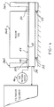
- Figure 3 shows lengths of inflatable hose seals 24 used with a channel 32 in which is disposed a drag conveyer 34 for moving accumulated solids.
- Figure 4 shows in block diagram form a series of machine tools 36A, 36B, 36C arranged in a series such as in a transfer line.
- a downwardly sloping coolant collection trough 38 extends beneath and along the series of machine tools 36A-36C so as to collect coolant draining from the various surfaces drenched by the cooling streams.
- a pair of inflatable hose seals 40 are positioned between the top side edges 42 of the collection trough 38 and undersurfaces 44 of the machine tools 36 and are inflated by connection to an air pressure source 46 so as to be tightly fit into the gap therebetween to close off and seal off that opening and prevent any escape of coolant onto the adjacent floor areas.
- the slope of the trough 38 creates a varying depth gap, which is accommodated by variable extension of the top of the hose seals 40 when inflated.
- Auxiliary plates 50 can be provided bridging any gaps between the machine tool undersurfaces 44 to provide more or less continuous sealing surfaces.
- the collection trough 38 can itself be of constant depth, and the slope established by adjustable height threaded supports 52 provided at spaced intervals.
- Fixed skids of varying heights can also be employed enabling fork lift handling of the trough, which can be formed in sections, when each section is put in place beneath the machine tool bases.
Landscapes
- Engineering & Computer Science (AREA)
- Mechanical Engineering (AREA)
- General Engineering & Computer Science (AREA)
- Physics & Mathematics (AREA)
- Architecture (AREA)
- Fluid Mechanics (AREA)
- Auxiliary Devices For Machine Tools (AREA)
Applications Claiming Priority (2)
| Application Number | Priority Date | Filing Date | Title |
|---|---|---|---|
| US09/056,224 US6116616A (en) | 1998-04-07 | 1998-04-07 | Sealing arrangement for machine/tool coolant collection troughs |
| US56224 | 1998-04-07 |
Publications (3)
| Publication Number | Publication Date |
|---|---|
| EP0949044A2 true EP0949044A2 (de) | 1999-10-13 |
| EP0949044A3 EP0949044A3 (de) | 2000-12-06 |
| EP0949044B1 EP0949044B1 (de) | 2003-05-02 |
Family
ID=22003015
Family Applications (1)
| Application Number | Title | Priority Date | Filing Date |
|---|---|---|---|
| EP99100719A Revoked EP0949044B1 (de) | 1998-04-07 | 1999-01-15 | Dichtungsanordnung von Trögen einer Werkzeugmaschine zur Sammlung von Kühlmittel |
Country Status (4)
| Country | Link |
|---|---|
| US (1) | US6116616A (de) |
| EP (1) | EP0949044B1 (de) |
| CA (1) | CA2257022C (de) |
| DE (1) | DE69907315T2 (de) |
Cited By (6)
| Publication number | Priority date | Publication date | Assignee | Title |
|---|---|---|---|---|
| EP1285724A3 (de) * | 2001-07-27 | 2003-05-07 | GROB-Werke Burkhart Grob e.K. | Maschine oder Anlage mit einem Kanal und Verfahren zur Montage eines Kanals |
| DE10347913A1 (de) * | 2003-10-10 | 2005-05-04 | Grob Werke Burkhart Grob Ek | Produktionslinie |
| US7044693B2 (en) * | 2003-09-30 | 2006-05-16 | Mori Seiki Co., Ltd. | Machine tool |
| EP1685924A1 (de) * | 2005-01-26 | 2006-08-02 | MANN+HUMMEL GmbH | Sammeltrog für eine Werkzeugmaschine |
| EP3778116A4 (de) * | 2018-09-06 | 2021-06-09 | Yamazaki Mazak Corporation | Werkzeugaufbewahrungsvorrichtung, bearbeitungswerkzeug und komplexes bearbeitungswerkzeug |
| IT202100019238A1 (it) * | 2021-07-20 | 2023-01-20 | Cms Spa | Apparato per il posizionamento di elementi di bloccaggio pezzo |
Families Citing this family (8)
| Publication number | Priority date | Publication date | Assignee | Title |
|---|---|---|---|---|
| JP4306073B2 (ja) * | 2000-01-31 | 2009-07-29 | ブラザー工業株式会社 | 工作機械のカバー装置およびカバー装置の組立方法 |
| US6948720B1 (en) * | 2002-12-10 | 2005-09-27 | Carlson James D | Computer controlled positioning table |
| US7387478B2 (en) * | 2004-08-27 | 2008-06-17 | Ford Motor Company | Machining system with integrated chip hopper |
| ITFI20070095A1 (it) * | 2007-04-18 | 2008-10-19 | Casafortes Hld S R L | Apparato per la protezione di ambienti chiusi da allagamento o contaminazioni. |
| US8813916B2 (en) * | 2008-04-16 | 2014-08-26 | Clear View Enclosures, Inc. | Underground enclosure system for storing components, cables, and the like |
| US20140273768A1 (en) * | 2013-03-15 | 2014-09-18 | Omax Corporation | Waterjet systems having sectional catcher tanks and related devices, systems and methods |
| SE539200C2 (en) * | 2015-09-09 | 2017-05-09 | BAE Systems Hägglunds AB | Sealing arrangement for an amphibious vehicle |
| US12179299B2 (en) * | 2018-08-07 | 2024-12-31 | Illinois Tool Works Inc. | Machine tool with recirculating coolant filtration system |
Family Cites Families (11)
| Publication number | Priority date | Publication date | Assignee | Title |
|---|---|---|---|---|
| US2978095A (en) * | 1958-01-16 | 1961-04-04 | Andrew W Jenike | Elevating belt conveyor for discrete materials in bulk |
| US3178779A (en) * | 1962-06-28 | 1965-04-20 | North American Aviation Inc | Multi-cell inflatable seal |
| DE2633173C2 (de) * | 1975-07-26 | 1985-02-14 | Pitcraft Summit Ltd., Barnsley, Yorkshire | Druckmittelführungsskanal, insbesondere an einem Abbauförderer einer Kohlegewinnungseinrichtung |
| GB2030900B (en) * | 1978-10-05 | 1982-08-25 | Cera Internat Ltd | Swarf removal |
| US4685361A (en) * | 1980-10-20 | 1987-08-11 | The Warner & Swasey Company | Machine tool |
| GB8514598D0 (en) * | 1985-06-10 | 1985-07-10 | Davy Mckee Poole | Lubrication of rolling mills |
| SU1386422A2 (ru) * | 1986-10-02 | 1988-04-07 | Oborok Vasilij L | Устройство дл ограждени зоны резани |
| JPH06106443A (ja) * | 1992-09-29 | 1994-04-19 | Toyoda Mach Works Ltd | 切粉処理装置 |
| US5567048A (en) * | 1994-10-14 | 1996-10-22 | Hammonds Technical Services, Inc. | Apparatus and method for injecting dry particulate material in a fluid flow line |
| FR2751254B1 (fr) * | 1996-07-19 | 1998-08-21 | Renault | Dispositif pour enlever les copeaux projetes par la tete d'usinage d'une machine outil |
| DE19645904A1 (de) * | 1996-11-07 | 1998-05-20 | Hausach Umformtechnik | Blähdichtring |
-
1998
- 1998-04-07 US US09/056,224 patent/US6116616A/en not_active Expired - Lifetime
- 1998-12-29 CA CA002257022A patent/CA2257022C/en not_active Expired - Fee Related
-
1999
- 1999-01-15 EP EP99100719A patent/EP0949044B1/de not_active Revoked
- 1999-01-15 DE DE69907315T patent/DE69907315T2/de not_active Revoked
Cited By (9)
| Publication number | Priority date | Publication date | Assignee | Title |
|---|---|---|---|---|
| EP1285724A3 (de) * | 2001-07-27 | 2003-05-07 | GROB-Werke Burkhart Grob e.K. | Maschine oder Anlage mit einem Kanal und Verfahren zur Montage eines Kanals |
| US7044693B2 (en) * | 2003-09-30 | 2006-05-16 | Mori Seiki Co., Ltd. | Machine tool |
| DE10347913A1 (de) * | 2003-10-10 | 2005-05-04 | Grob Werke Burkhart Grob Ek | Produktionslinie |
| EP1685924A1 (de) * | 2005-01-26 | 2006-08-02 | MANN+HUMMEL GmbH | Sammeltrog für eine Werkzeugmaschine |
| US7241090B2 (en) * | 2005-01-26 | 2007-07-10 | Mann & Hummel Gmbh | Collecting trough for a machine tool |
| EP3778116A4 (de) * | 2018-09-06 | 2021-06-09 | Yamazaki Mazak Corporation | Werkzeugaufbewahrungsvorrichtung, bearbeitungswerkzeug und komplexes bearbeitungswerkzeug |
| US11919107B2 (en) | 2018-09-06 | 2024-03-05 | Yamazaki Mazak Corporation | Tool storage, machine tool, hybrid working machine |
| IT202100019238A1 (it) * | 2021-07-20 | 2023-01-20 | Cms Spa | Apparato per il posizionamento di elementi di bloccaggio pezzo |
| EP4122642A1 (de) * | 2021-07-20 | 2023-01-25 | C.M.S. S.p.A. | Vorrichtung zum positionieren von werkstückspannelementen |
Also Published As
| Publication number | Publication date |
|---|---|
| DE69907315D1 (de) | 2003-06-05 |
| DE69907315T2 (de) | 2004-03-11 |
| EP0949044A3 (de) | 2000-12-06 |
| EP0949044B1 (de) | 2003-05-02 |
| CA2257022C (en) | 2007-09-11 |
| US6116616A (en) | 2000-09-12 |
| CA2257022A1 (en) | 1999-10-07 |
Similar Documents
| Publication | Publication Date | Title |
|---|---|---|
| US6116616A (en) | Sealing arrangement for machine/tool coolant collection troughs | |
| US5257652A (en) | Fluid collection system for installation underground and method of installation | |
| US5980735A (en) | Collection system for machine tool coolant | |
| US7258749B2 (en) | Wash fluid containment system | |
| EP0006925B1 (de) | Methode und anordnung zur reinigung einer schneidflüssigkeit | |
| US5634485A (en) | Method and apparatus for retrofitting drilling rigs with a catch pan | |
| US5975332A (en) | Compact spill containment pan | |
| US5730872A (en) | Apparatus for separating a mixture of liquids | |
| KR900700702A (ko) | 좁은 통로의 오물수집탱크조립체 및 원거리 조작식 신속 연결-분리 커플링 및 이를 사용한 시스템 | |
| US6223855B1 (en) | Device for dismantling vehicles, in particular for draining the latter | |
| US5435458A (en) | Chemical spill containment apparatus | |
| JPH05506829A (ja) | 液体収集用マット | |
| CZ294671B6 (cs) | Betonová tvárnice | |
| CN105645074B (zh) | 一种高效的土压平衡盾构皮带输送机刮泥系统 | |
| US6708737B1 (en) | Velocity flume and method for collecting machining coolant | |
| US4202364A (en) | Method for separating fluids by means of pressure differential | |
| US4831955A (en) | Arrangement in a water craft for collecting oil or other contaminants present on the surface of water | |
| US5086795A (en) | Removable flushing system for machine tool coolant return system flumes | |
| JPH0681849A (ja) | 軸受の排脂方法及びその装置 | |
| EP0172013A2 (de) | Vakuumfilteranlage | |
| KR200270877Y1 (ko) | 코일이송용 돌리카의 오일회수장치 | |
| US20070235090A1 (en) | Fluid processing system | |
| KR20120025093A (ko) | 시추구역의 로터리 테이블 주위 실링 장치 | |
| CN119609950A (zh) | 一种水刀切割机 | |
| JP2020079494A (ja) | 排水吸引回収装置 |
Legal Events
| Date | Code | Title | Description |
|---|---|---|---|
| PUAI | Public reference made under article 153(3) epc to a published international application that has entered the european phase |
Free format text: ORIGINAL CODE: 0009012 |
|
| AK | Designated contracting states |
Kind code of ref document: A2 Designated state(s): DE ES FR GB IT SE |
|
| AX | Request for extension of the european patent |
Free format text: AL;LT;LV;MK;RO;SI |
|
| PUAL | Search report despatched |
Free format text: ORIGINAL CODE: 0009013 |
|
| AK | Designated contracting states |
Kind code of ref document: A3 Designated state(s): AT BE CH CY DE DK ES FI FR GB GR IE IT LI LU MC NL PT SE |
|
| AX | Request for extension of the european patent |
Free format text: AL;LT;LV;MK;RO;SI |
|
| 17P | Request for examination filed |
Effective date: 20010111 |
|
| AKX | Designation fees paid |
Free format text: DE ES FR GB IT SE |
|
| GRAH | Despatch of communication of intention to grant a patent |
Free format text: ORIGINAL CODE: EPIDOS IGRA |
|
| GRAH | Despatch of communication of intention to grant a patent |
Free format text: ORIGINAL CODE: EPIDOS IGRA |
|
| GRAA | (expected) grant |
Free format text: ORIGINAL CODE: 0009210 |
|
| AK | Designated contracting states |
Designated state(s): DE ES FR GB IT SE |
|
| PG25 | Lapsed in a contracting state [announced via postgrant information from national office to epo] |
Ref country code: IT Free format text: LAPSE BECAUSE OF FAILURE TO SUBMIT A TRANSLATION OF THE DESCRIPTION OR TO PAY THE FEE WITHIN THE PRESCRIBED TIME-LIMIT;WARNING: LAPSES OF ITALIAN PATENTS WITH EFFECTIVE DATE BEFORE 2007 MAY HAVE OCCURRED AT ANY TIME BEFORE 2007. THE CORRECT EFFECTIVE DATE MAY BE DIFFERENT FROM THE ONE RECORDED. Effective date: 20030502 |
|
| REG | Reference to a national code |
Ref country code: GB Ref legal event code: FG4D |
|
| REF | Corresponds to: |
Ref document number: 69907315 Country of ref document: DE Date of ref document: 20030605 Kind code of ref document: P |
|
| PG25 | Lapsed in a contracting state [announced via postgrant information from national office to epo] |
Ref country code: SE Free format text: LAPSE BECAUSE OF FAILURE TO SUBMIT A TRANSLATION OF THE DESCRIPTION OR TO PAY THE FEE WITHIN THE PRESCRIBED TIME-LIMIT Effective date: 20030802 |
|
| PG25 | Lapsed in a contracting state [announced via postgrant information from national office to epo] |
Ref country code: ES Free format text: LAPSE BECAUSE OF FAILURE TO SUBMIT A TRANSLATION OF THE DESCRIPTION OR TO PAY THE FEE WITHIN THE PRESCRIBED TIME-LIMIT Effective date: 20030813 |
|
| PLBQ | Unpublished change to opponent data |
Free format text: ORIGINAL CODE: EPIDOS OPPO |
|
| PLBI | Opposition filed |
Free format text: ORIGINAL CODE: 0009260 |
|
| ET | Fr: translation filed | ||
| PLAX | Notice of opposition and request to file observation + time limit sent |
Free format text: ORIGINAL CODE: EPIDOSNOBS2 |
|
| 26 | Opposition filed |
Opponent name: KRAUSECO WERKZEUGMASCHINEN GMBH Effective date: 20040130 |
|
| PLAX | Notice of opposition and request to file observation + time limit sent |
Free format text: ORIGINAL CODE: EPIDOSNOBS2 |
|
| PLBB | Reply of patent proprietor to notice(s) of opposition received |
Free format text: ORIGINAL CODE: EPIDOSNOBS3 |
|
| PLAY | Examination report in opposition despatched + time limit |
Free format text: ORIGINAL CODE: EPIDOSNORE2 |
|
| PLBC | Reply to examination report in opposition received |
Free format text: ORIGINAL CODE: EPIDOSNORE3 |
|
| PGFP | Annual fee paid to national office [announced via postgrant information from national office to epo] |
Ref country code: FR Payment date: 20060119 Year of fee payment: 8 |
|
| PGFP | Annual fee paid to national office [announced via postgrant information from national office to epo] |
Ref country code: DE Payment date: 20060227 Year of fee payment: 8 |
|
| RDAF | Communication despatched that patent is revoked |
Free format text: ORIGINAL CODE: EPIDOSNREV1 |
|
| RDAG | Patent revoked |
Free format text: ORIGINAL CODE: 0009271 |
|
| STAA | Information on the status of an ep patent application or granted ep patent |
Free format text: STATUS: PATENT REVOKED |
|
| 27W | Patent revoked |
Effective date: 20060608 |
|
| PGFP | Annual fee paid to national office [announced via postgrant information from national office to epo] |
Ref country code: GB Payment date: 20060123 Year of fee payment: 8 |