EP0949054A1 - Procédé et dispositif pour filtrer des matières plastiques dans les machines à mouler par injection - Google Patents
Procédé et dispositif pour filtrer des matières plastiques dans les machines à mouler par injection Download PDFInfo
- Publication number
- EP0949054A1 EP0949054A1 EP99250028A EP99250028A EP0949054A1 EP 0949054 A1 EP0949054 A1 EP 0949054A1 EP 99250028 A EP99250028 A EP 99250028A EP 99250028 A EP99250028 A EP 99250028A EP 0949054 A1 EP0949054 A1 EP 0949054A1
- Authority
- EP
- European Patent Office
- Prior art keywords
- filter element
- filter
- piston
- slide
- unit
- Prior art date
- Legal status (The legal status is an assumption and is not a legal conclusion. Google has not performed a legal analysis and makes no representation as to the accuracy of the status listed.)
- Granted
Links
- 238000000034 method Methods 0.000 title claims abstract description 9
- 238000001746 injection moulding Methods 0.000 title claims description 12
- 239000000463 material Substances 0.000 title claims description 12
- 239000004033 plastic Substances 0.000 title claims description 12
- 229920003023 plastic Polymers 0.000 title claims description 12
- 238000001914 filtration Methods 0.000 title claims description 5
- 238000007789 sealing Methods 0.000 claims description 33
- 238000006073 displacement reaction Methods 0.000 claims description 9
- 238000005266 casting Methods 0.000 claims description 6
- 150000001875 compounds Chemical class 0.000 claims description 5
- 239000007921 spray Substances 0.000 claims description 4
- RTAQQCXQSZGOHL-UHFFFAOYSA-N Titanium Chemical compound [Ti] RTAQQCXQSZGOHL-UHFFFAOYSA-N 0.000 claims 1
- 229910052719 titanium Inorganic materials 0.000 claims 1
- 239000010936 titanium Substances 0.000 claims 1
- 239000000155 melt Substances 0.000 abstract description 3
- 238000010438 heat treatment Methods 0.000 abstract description 2
- 238000002347 injection Methods 0.000 abstract 2
- 239000007924 injection Substances 0.000 abstract 2
- 238000000465 moulding Methods 0.000 abstract 2
- 239000002184 metal Substances 0.000 description 4
- 239000004413 injection moulding compound Substances 0.000 description 3
- 238000011161 development Methods 0.000 description 2
- 230000018109 developmental process Effects 0.000 description 2
- 238000003860 storage Methods 0.000 description 2
- 230000000903 blocking effect Effects 0.000 description 1
- 239000000356 contaminant Substances 0.000 description 1
- 230000007547 defect Effects 0.000 description 1
- 238000009826 distribution Methods 0.000 description 1
- 239000013013 elastic material Substances 0.000 description 1
- 238000001125 extrusion Methods 0.000 description 1
- 238000004519 manufacturing process Methods 0.000 description 1
- 230000003014 reinforcing effect Effects 0.000 description 1
- 238000012216 screening Methods 0.000 description 1
- 238000005507 spraying Methods 0.000 description 1
- 229910001220 stainless steel Inorganic materials 0.000 description 1
- 239000010935 stainless steel Substances 0.000 description 1
- 239000000126 substance Substances 0.000 description 1
- 229920001169 thermoplastic Polymers 0.000 description 1
- 239000004416 thermosoftening plastic Substances 0.000 description 1
- 230000001960 triggered effect Effects 0.000 description 1
- 238000010792 warming Methods 0.000 description 1
Images


Classifications
-
- B—PERFORMING OPERATIONS; TRANSPORTING
- B29—WORKING OF PLASTICS; WORKING OF SUBSTANCES IN A PLASTIC STATE IN GENERAL
- B29C—SHAPING OR JOINING OF PLASTICS; SHAPING OF MATERIAL IN A PLASTIC STATE, NOT OTHERWISE PROVIDED FOR; AFTER-TREATMENT OF THE SHAPED PRODUCTS, e.g. REPAIRING
- B29C45/00—Injection moulding, i.e. forcing the required volume of moulding material through a nozzle into a closed mould; Apparatus therefor
- B29C45/17—Component parts, details or accessories; Auxiliary operations
- B29C45/20—Injection nozzles
- B29C45/24—Cleaning equipment
-
- B—PERFORMING OPERATIONS; TRANSPORTING
- B29—WORKING OF PLASTICS; WORKING OF SUBSTANCES IN A PLASTIC STATE IN GENERAL
- B29C—SHAPING OR JOINING OF PLASTICS; SHAPING OF MATERIAL IN A PLASTIC STATE, NOT OTHERWISE PROVIDED FOR; AFTER-TREATMENT OF THE SHAPED PRODUCTS, e.g. REPAIRING
- B29C45/00—Injection moulding, i.e. forcing the required volume of moulding material through a nozzle into a closed mould; Apparatus therefor
- B29C45/17—Component parts, details or accessories; Auxiliary operations
- B29C45/1753—Cleaning or purging, e.g. of the injection unit
-
- B—PERFORMING OPERATIONS; TRANSPORTING
- B29—WORKING OF PLASTICS; WORKING OF SUBSTANCES IN A PLASTIC STATE IN GENERAL
- B29C—SHAPING OR JOINING OF PLASTICS; SHAPING OF MATERIAL IN A PLASTIC STATE, NOT OTHERWISE PROVIDED FOR; AFTER-TREATMENT OF THE SHAPED PRODUCTS, e.g. REPAIRING
- B29C45/00—Injection moulding, i.e. forcing the required volume of moulding material through a nozzle into a closed mould; Apparatus therefor
- B29C45/17—Component parts, details or accessories; Auxiliary operations
- B29C45/46—Means for plasticising or homogenising the moulding material or forcing it into the mould
- B29C45/57—Exerting after-pressure on the moulding material
Definitions
- the invention relates to a method for filtering plastics in Injection molding machines, in which between the plasticizing unit and the Mold cavity is arranged a holding device receiving a filter element, and a corresponding facility.
- a screening system is known from plastics 87 (1997), pages 154-159 (page 156), at the sieve points in a rectangular slider (cassette) or a round one Bolts are inserted.
- a hydraulic drive is used for manual triggering or automatically when a defined pressure limit is reached by moving the Screen surface support triggered the change.
- a filter device for plastic melts is known from DE 44 19 284 C1, at the sieve inserts are arranged in a power-operated sliding slide. Seals are arranged on both sides of the slide, at least one the seals has a sealing body made of metal, the one Encloses cavity, which is filled with a substance, the thermal Expansion coefficient exceeds that of the material of the sealing body.
- the seal is made of metal, for example stainless steel Sealing body practically relaxed. By warming through the flowing The sealing body including the material filling it becomes thermoplastic expands so that in operation after thermal expansion or deformation the face of the seal is firmly and sealingly against the slide.
- the invention has set itself the goal of a method and a corresponding Device for filtering plastics in injection molding machines to create a safe with simple and constructive means at high mass pressures Removal of contaminants from the plastic mass is guaranteed.
- a preheated filter element is used when changing the filter, which is loaded with plastic mass that so long from the mold cavity is kept away until the casting compound is recognized as suitable and therefore free of defects Processing is fed.
- the blocking position of the shut-off element prevents any influence on the filter and the screw from the tool or distribution system, e.g. Hot runner at Multi-components etc.
- the rinsing position makes this possible in particular after changing the filter units Spraying out the air volume and the old mass when starting the Injection molding machine and when changing the filter.
- the slide in which the active filter is mounted can be moved and movable into a position in which its inclusion of the filter element with a piston-shaped displacement unit corresponds through which the used Filter element can be ejected and at the same time the fresh filter element can be used.
- the displacement unit has a preheating device in the area of the filter holder, through which the filter elements can be preheated to operating temperature.
- the slide designed as a carrier plate with the the dirty filter unit is pulled out of the filter head.
- the Piston of the displacement unit By means of the Piston of the displacement unit, the preheated filter element in the carrier plate inserted.
- the soiled element on the opposite side is placed on a Ejection gutter ejected.
- the filter element is also in its Operating position influenced thermally. This is in the slider in the area of the recording a filter heater is provided for the filter element.
- the slide holding the filter element should be easy to move for changing, kept tightly closed during operation and no leaks allow.
- sealing rings on both sides of the slide to provide.
- the present case is on the side inclined to the plasticizing unit an at least two-part sealing ring between slide and housing provided that either depending on the mass pressure present in the channel is free of play or can be pressed against the slide.
- the one sealing part of the sealing ring is roof-shaped, while the other has a triangular shape, both of which are inclined Touch surface.
- Both ring parts are made exclusively of metal, whereby at least the roof-shaped sealing ring preferably made of highly elastic material is made.
- both sealing rings are spring-back and lean back slightly biased against each other.
- the roof-shaped sealing ring the diameter, being its the triangular sealing ring inclined sloping surface during its radial opening the triangular sealing ring moved axially and pressed against the slide.
- the angle of the touching sloping surfaces of both sealing parts is chosen so that they do not wedge and spring back to their starting position when depressurized.
- a metal with a low modulus of elasticity was provided as the material Deformation favors.
- this is in the connecting line provided shut-off device designed as a 3-way valve and with a memory connectable.
- the memory is designed as a piston-cylinder unit, which in the hydraulic or electric drive is operable. The piston rod of the piston-cylinder unit is thermally separated, so that there is no negative influence on the Injection molding compound enters.
- FIG. 1 shows an injection molding unit with a plasticizing unit 11, in which one Auger 12 is driven by a worm drive 13.
- the housing 18 of the Plasticizing unit 11 has a channel 14 on the mouth side, which is connected via a Connection line 35 is connected to a nozzle 15, via the Injection molding compound is guided to the mold cavity 17 of a tool 16.
- a slide 61 is arranged, which has a receptacle 62 for has a filter element 21, the slide 61 perpendicular to the main axis I is movable.
- the receptacle 62 for the filter element 21 is enveloped by a filter heater 72.
- the slide 61 corresponds to one in its filter change position piston-shaped displacement unit 66, the secondary axis II parallel to the main axis I is arranged and has a filter holder 63 in the mouth region, in which a fresh filter element 21 can be used.
- the center of the receptacle 62 becomes the main axis I Plasticizing unit 11 moved to the secondary axis II of the displacement unit 66.
- a piston-cylinder unit 64 arranged in the displacement unit 66 the filter element 21 from the filter holder 63 into the receptacle 62 of the slide 61 brought, the used filter element (not shown here) from the Slider 61 is removed.
- the filter holder 63 has a preheater 71 through which the fresh one Filter elements 21 can be brought to operating temperature.
- the fresh filter elements 21 are via a magazine not shown Filter holder 63 supplied.
- shut-off device 31 is provided in the Connecting line 35 , which as a 3-way valve 33 is designed.
- the channel 14 and thus the filtered material are in one position the mold cavity 17, in a further position, the channel 14 is via a Branch 36 connected to a spray container 37.
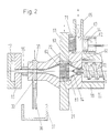
- FIG. 2 shows a section of FIG. 1 in the area of slide 61 and of the shut-off device 31.
- the shut-off device 31 is designed here as a slide with the Position passage, blocked and redirecting.
- sealing ring 81 is shown in FIG. 2 in addition to FIG. 1.
- the Sealing ring 81 consists of two sealing parts, namely a roof-shaped Sealing part 82 and a triangular sealing part 83, which extend over a complete Touch surface.
- FIG. 3 shows an injection molding unit, in addition to the branch 36 Memory 41 is connected to the shut-off device 31.
- the memory 41 has an adjusting element 42, which acts as a piston-cylinder unit 43 is formed.
- the piston rod 44 of the piston-cylinder unit is connected to one hydraulic drive or an electric drive (not shown here) connectable.
- the piston rod 44 consists in one area of a material 46 through which the Piston 45 is thermally separable from the drive.
Landscapes
- Engineering & Computer Science (AREA)
- Manufacturing & Machinery (AREA)
- Mechanical Engineering (AREA)
- Injection Moulding Of Plastics Or The Like (AREA)
- Moulds For Moulding Plastics Or The Like (AREA)
- Processing And Handling Of Plastics And Other Materials For Molding In General (AREA)
- Extrusion Moulding Of Plastics Or The Like (AREA)
- Blow-Moulding Or Thermoforming Of Plastics Or The Like (AREA)
Applications Claiming Priority (2)
| Application Number | Priority Date | Filing Date | Title |
|---|---|---|---|
| DE19811273 | 1998-03-11 | ||
| DE19811273A DE19811273C2 (de) | 1998-03-11 | 1998-03-11 | Verfahren und Vorrichtung zum Filtern von Kunststoffen in Spritzgießmaschinen |
Publications (2)
| Publication Number | Publication Date |
|---|---|
| EP0949054A1 true EP0949054A1 (fr) | 1999-10-13 |
| EP0949054B1 EP0949054B1 (fr) | 2001-12-12 |
Family
ID=7861008
Family Applications (1)
| Application Number | Title | Priority Date | Filing Date |
|---|---|---|---|
| EP99250028A Expired - Lifetime EP0949054B1 (fr) | 1998-03-11 | 1999-01-26 | Procédé et dispositif pour filtrer des matières plastiques dans les machines à mouler par injection |
Country Status (4)
| Country | Link |
|---|---|
| US (1) | US6196820B1 (fr) |
| EP (1) | EP0949054B1 (fr) |
| AT (1) | ATE210544T1 (fr) |
| DE (2) | DE19811273C2 (fr) |
Families Citing this family (13)
| Publication number | Priority date | Publication date | Assignee | Title |
|---|---|---|---|---|
| US7393479B2 (en) * | 2004-10-15 | 2008-07-01 | Husky Injection Molding Systems Ltd. | Injection molding three-way shut off valve |
| WO2010144994A1 (fr) * | 2009-06-19 | 2010-12-23 | Husky Injection Molding Systems Ltd. | Procédé de régulation de pression de fusion selon une plage de pression cible dans une unité d'injection ayant un filtre |
| US8628323B2 (en) * | 2009-06-25 | 2014-01-14 | Husky Injection Molding Systems Ltd. | Injection molding system including a melt filter, the filter being located before first instance of melt accumulation |
| JP5535595B2 (ja) * | 2009-11-25 | 2014-07-02 | 日精エー・エス・ビー機械株式会社 | 射出装置及び樹脂の射出方法 |
| EP3233411B1 (fr) | 2014-12-15 | 2020-06-17 | Husky Injection Molding Systems Ltd. | Machine de moulage par injection |
| AT516900A1 (de) * | 2015-03-09 | 2016-09-15 | Dr Collin Gmbh | Vorrichtung und Verfahren zum Testen von Werkstoffen |
| EP3308940B1 (fr) * | 2016-10-17 | 2025-03-05 | Next Generation Analytics GmbH | Système de filtre pour les fluides visqueux ou fortement visqueux, surtout plastique fondu et procédé de filtration des liquides visqueux ou fortement visqueux |
| US11260570B2 (en) * | 2018-05-07 | 2022-03-01 | PSI-Polymer Systems, Inc. | Filtration apparatuses and screen changer devices for polymer processing and related methods |
| CN110587919B (zh) * | 2019-09-19 | 2023-11-24 | 五邑大学 | 换网器及其换网方法 |
| AT524784B1 (de) * | 2021-04-07 | 2022-09-15 | Engel Austria Gmbh | Plastifizieraggregat für eine Formgebungsmaschine und Verfahren zum Betreiben eines solchen |
| AT525668B1 (de) * | 2022-07-11 | 2023-06-15 | Engel Austria Gmbh | Plastifiziereinheit für eine Formgebungsmaschine |
| AT525547B1 (de) * | 2022-07-11 | 2023-05-15 | Engel Austria Gmbh | Filtervorrichtung |
| CN117400483B (zh) * | 2023-12-06 | 2024-10-22 | 太仓市天丝利塑化有限公司 | 一种双筒式汽车注塑配件注塑机 |
Citations (6)
| Publication number | Priority date | Publication date | Assignee | Title |
|---|---|---|---|---|
| GB1047533A (en) * | 1963-05-15 | 1966-11-09 | Barmer Machinenfabrik Ag | Improvements in or relating to screw extruders |
| US3709644A (en) * | 1970-11-25 | 1973-01-09 | J Farrell | Time saver plastic draw-back valve assembly |
| US4416605A (en) * | 1981-05-07 | 1983-11-22 | Kabushiki Kaisha Kobe Seiko Sho | Screen/diverter changing mechanism for extruders |
| JPH0724877A (ja) * | 1993-07-07 | 1995-01-27 | Japan Steel Works Ltd:The | 射出成形機のパージ排出機能付ノズル |
| WO1995010404A1 (fr) * | 1993-10-13 | 1995-04-20 | Synergistic Extrusion Technologies, Inc. | Dispositif d'etancheite pour appareil de filtrage de polymeres |
| US5439589A (en) * | 1994-05-09 | 1995-08-08 | Trafalgar House Inc. | Sealing means for slide plate screen changer |
Family Cites Families (6)
| Publication number | Priority date | Publication date | Assignee | Title |
|---|---|---|---|---|
| US3962092A (en) * | 1975-01-10 | 1976-06-08 | The Dow Chemical Company | Screen changer |
| JPS5927698B2 (ja) * | 1977-11-28 | 1984-07-07 | 株式会社日本製鋼所 | プラスチツク押出機における自動「ろ」網交換装置 |
| US4814186A (en) * | 1988-02-29 | 1989-03-21 | Beringer Co., Inc. | Polymer filtration apparatus |
| DE3902061A1 (de) * | 1989-01-25 | 1990-07-26 | Gneuss Kunststofftechnik Gmbh | Siebvorrichtung zur reinigung von kunststoffschmelzen |
| DE4419284C1 (de) * | 1994-06-01 | 1995-10-26 | Gneuss Kunststofftechnik Gmbh | Plattensiebwechsler |
| US6010625A (en) * | 1997-10-16 | 2000-01-04 | Beringer Llc | Screen changer with controlled gap |
-
1998
- 1998-03-11 DE DE19811273A patent/DE19811273C2/de not_active Expired - Fee Related
-
1999
- 1999-01-26 AT AT99250028T patent/ATE210544T1/de not_active IP Right Cessation
- 1999-01-26 DE DE59900521T patent/DE59900521D1/de not_active Expired - Fee Related
- 1999-01-26 EP EP99250028A patent/EP0949054B1/fr not_active Expired - Lifetime
- 1999-03-11 US US09/267,479 patent/US6196820B1/en not_active Expired - Fee Related
Patent Citations (6)
| Publication number | Priority date | Publication date | Assignee | Title |
|---|---|---|---|---|
| GB1047533A (en) * | 1963-05-15 | 1966-11-09 | Barmer Machinenfabrik Ag | Improvements in or relating to screw extruders |
| US3709644A (en) * | 1970-11-25 | 1973-01-09 | J Farrell | Time saver plastic draw-back valve assembly |
| US4416605A (en) * | 1981-05-07 | 1983-11-22 | Kabushiki Kaisha Kobe Seiko Sho | Screen/diverter changing mechanism for extruders |
| JPH0724877A (ja) * | 1993-07-07 | 1995-01-27 | Japan Steel Works Ltd:The | 射出成形機のパージ排出機能付ノズル |
| WO1995010404A1 (fr) * | 1993-10-13 | 1995-04-20 | Synergistic Extrusion Technologies, Inc. | Dispositif d'etancheite pour appareil de filtrage de polymeres |
| US5439589A (en) * | 1994-05-09 | 1995-08-08 | Trafalgar House Inc. | Sealing means for slide plate screen changer |
Non-Patent Citations (1)
| Title |
|---|
| PATENT ABSTRACTS OF JAPAN vol. 95, no. 4 31 May 1995 (1995-05-31) * |
Also Published As
| Publication number | Publication date |
|---|---|
| ATE210544T1 (de) | 2001-12-15 |
| DE59900521D1 (de) | 2002-01-24 |
| EP0949054B1 (fr) | 2001-12-12 |
| DE19811273A1 (de) | 1999-09-30 |
| US6196820B1 (en) | 2001-03-06 |
| DE19811273C2 (de) | 2000-01-27 |
Similar Documents
| Publication | Publication Date | Title |
|---|---|---|
| DE3850543T2 (de) | Verfahren, System und darin angewendete Vorrichtung zum Spritzgiessen und dadurch hergestellter Kunststoffgegenstand. | |
| DE69319825T2 (de) | Verfahren und Vorrichtung zur Fluidverdichtung eines spritzgegossenen Kunststoffes | |
| EP0949054B1 (fr) | Procédé et dispositif pour filtrer des matières plastiques dans les machines à mouler par injection | |
| DE69523651T2 (de) | Spritzgiessvorrichtung vom Vorplastifiziertyp | |
| DE69311336T2 (de) | Durch Gas unterstütztes Spritzgiessen | |
| DE1142058B (de) | Verfahren zur Verarbeitung thermoplastischer Kunststoffe in einer Spritzgiessmaschine | |
| DE3242389C2 (fr) | ||
| DE19606045A1 (de) | Verfahren zum Spritzgießen von dreischichtigen Spritzlingen und Vorrichtung für die Durchführung des Verfahrens | |
| DE69919809T2 (de) | Mikrospritzgiessmaschine | |
| DE69007141T2 (de) | Vorrichtung und Verfahren zum Spritzgiessen. | |
| EP0846050B1 (fr) | Presse de moulage par injection avec systeme a canal chauffant integre | |
| DE3586151T2 (de) | Verfahren zum spritzgiessen fuer geschmolzenen kunststoff. | |
| DE3932416A1 (de) | Verfahren zum spritzgiessen von mehrkomponenten-kunststoffkoerpern und vorrichtung zur durchfuehrung des verfahrens | |
| DE69935667T2 (de) | Verfahren zum herstellen eines kraftfahrzeug-bauteils durch einspritzen von kunststoffmaterial, verfahren zum sequenziellen einspritzen von kunststoffmaterial, form zur durchführung des verfahrens, und so hergestelltes bauteil | |
| DE102004015879A1 (de) | Angussbuchse mit Anti-Nachfließ-Vorrichtung | |
| DE69525199T2 (de) | Formvorrichtung | |
| DE69021824T2 (de) | Verfahren zum Spritzgiessen und Vorrichtung dafür. | |
| DE19920331B4 (de) | Einspritzdüse für Spritzgießmaschinen | |
| DE2710779C2 (de) | Einspritzvorrichtung zum Spritzgießen von thermoplastischen Kunststoffen oder Kautschukmischungen | |
| WO1994007675A1 (fr) | Dispositif pour le moulage par injection d'articles en matiere plastique presentant des cavites, et son procede d'utilisation | |
| DE3516179A1 (de) | Verfahren und vorrichtung zum herstellen von gegenstaenden aus thermoplastischem kunststoff durch spritzgiessen | |
| DE19618960B4 (de) | Spritzgießvorrichtung mit verschiebbarer Düse zur Montage von Seitenangussdichtungen | |
| DE3211342A1 (de) | Kunststoffspritzpresse mit einer zufuehrvorrichtung zum zufuehren einer thermoplastischen masse | |
| EP0287001B1 (fr) | Dispositif de moulage par injection | |
| DE4221423C2 (de) | Verfahren und Vorrichtung zum Herstellen von Gegenständen aus thermoplastischem Kunststoff durch Spritzgießen |
Legal Events
| Date | Code | Title | Description |
|---|---|---|---|
| PUAI | Public reference made under article 153(3) epc to a published international application that has entered the european phase |
Free format text: ORIGINAL CODE: 0009012 |
|
| AK | Designated contracting states |
Kind code of ref document: A1 Designated state(s): AT CH DE FR IT LI NL |
|
| AX | Request for extension of the european patent |
Free format text: AL;LT;LV;MK;RO;SI |
|
| 17P | Request for examination filed |
Effective date: 19991215 |
|
| AKX | Designation fees paid |
Free format text: AT CH DE FR IT LI NL |
|
| GRAG | Despatch of communication of intention to grant |
Free format text: ORIGINAL CODE: EPIDOS AGRA |
|
| 17Q | First examination report despatched |
Effective date: 20010124 |
|
| GRAG | Despatch of communication of intention to grant |
Free format text: ORIGINAL CODE: EPIDOS AGRA |
|
| GRAG | Despatch of communication of intention to grant |
Free format text: ORIGINAL CODE: EPIDOS AGRA |
|
| GRAH | Despatch of communication of intention to grant a patent |
Free format text: ORIGINAL CODE: EPIDOS IGRA |
|
| RAP1 | Party data changed (applicant data changed or rights of an application transferred) |
Owner name: DEMAG ERGOTECH GMBH |
|
| GRAH | Despatch of communication of intention to grant a patent |
Free format text: ORIGINAL CODE: EPIDOS IGRA |
|
| GRAA | (expected) grant |
Free format text: ORIGINAL CODE: 0009210 |
|
| AK | Designated contracting states |
Kind code of ref document: B1 Designated state(s): AT CH DE FR IT LI NL |
|
| REF | Corresponds to: |
Ref document number: 210544 Country of ref document: AT Date of ref document: 20011215 Kind code of ref document: T |
|
| REG | Reference to a national code |
Ref country code: CH Ref legal event code: NV Representative=s name: E. BLUM & CO. PATENTANWAELTE Ref country code: CH Ref legal event code: EP |
|
| REF | Corresponds to: |
Ref document number: 59900521 Country of ref document: DE Date of ref document: 20020124 |
|
| ET | Fr: translation filed | ||
| PLBE | No opposition filed within time limit |
Free format text: ORIGINAL CODE: 0009261 |
|
| STAA | Information on the status of an ep patent application or granted ep patent |
Free format text: STATUS: NO OPPOSITION FILED WITHIN TIME LIMIT |
|
| 26N | No opposition filed | ||
| PGFP | Annual fee paid to national office [announced via postgrant information from national office to epo] |
Ref country code: NL Payment date: 20031231 Year of fee payment: 6 |
|
| PGFP | Annual fee paid to national office [announced via postgrant information from national office to epo] |
Ref country code: AT Payment date: 20040102 Year of fee payment: 6 |
|
| PGFP | Annual fee paid to national office [announced via postgrant information from national office to epo] |
Ref country code: CH Payment date: 20040106 Year of fee payment: 6 |
|
| PGFP | Annual fee paid to national office [announced via postgrant information from national office to epo] |
Ref country code: FR Payment date: 20040109 Year of fee payment: 6 |
|
| PGFP | Annual fee paid to national office [announced via postgrant information from national office to epo] |
Ref country code: DE Payment date: 20050106 Year of fee payment: 7 |
|
| PG25 | Lapsed in a contracting state [announced via postgrant information from national office to epo] |
Ref country code: IT Free format text: LAPSE BECAUSE OF NON-PAYMENT OF DUE FEES;WARNING: LAPSES OF ITALIAN PATENTS WITH EFFECTIVE DATE BEFORE 2007 MAY HAVE OCCURRED AT ANY TIME BEFORE 2007. THE CORRECT EFFECTIVE DATE MAY BE DIFFERENT FROM THE ONE RECORDED. Effective date: 20050126 Ref country code: AT Free format text: LAPSE BECAUSE OF NON-PAYMENT OF DUE FEES Effective date: 20050126 |
|
| PG25 | Lapsed in a contracting state [announced via postgrant information from national office to epo] |
Ref country code: LI Free format text: LAPSE BECAUSE OF NON-PAYMENT OF DUE FEES Effective date: 20050131 Ref country code: CH Free format text: LAPSE BECAUSE OF NON-PAYMENT OF DUE FEES Effective date: 20050131 |
|
| PG25 | Lapsed in a contracting state [announced via postgrant information from national office to epo] |
Ref country code: NL Free format text: LAPSE BECAUSE OF NON-PAYMENT OF DUE FEES Effective date: 20050801 |
|
| REG | Reference to a national code |
Ref country code: CH Ref legal event code: PL |
|
| PG25 | Lapsed in a contracting state [announced via postgrant information from national office to epo] |
Ref country code: FR Free format text: LAPSE BECAUSE OF NON-PAYMENT OF DUE FEES Effective date: 20050930 |
|
| NLV4 | Nl: lapsed or anulled due to non-payment of the annual fee |
Effective date: 20050801 |
|
| REG | Reference to a national code |
Ref country code: FR Ref legal event code: ST |
|
| PG25 | Lapsed in a contracting state [announced via postgrant information from national office to epo] |
Ref country code: DE Free format text: LAPSE BECAUSE OF NON-PAYMENT OF DUE FEES Effective date: 20060801 |