EP0949064A2 - Druckplattenanlage zum Verbinden von mehreren Materialbahnen - wovon jede mindestens eine flache Bahn und/oder mindestens eine gewölbte Bahn umfasst- zur Wellpappe - Google Patents
Druckplattenanlage zum Verbinden von mehreren Materialbahnen - wovon jede mindestens eine flache Bahn und/oder mindestens eine gewölbte Bahn umfasst- zur Wellpappe Download PDFInfo
- Publication number
- EP0949064A2 EP0949064A2 EP99106722A EP99106722A EP0949064A2 EP 0949064 A2 EP0949064 A2 EP 0949064A2 EP 99106722 A EP99106722 A EP 99106722A EP 99106722 A EP99106722 A EP 99106722A EP 0949064 A2 EP0949064 A2 EP 0949064A2
- Authority
- EP
- European Patent Office
- Prior art keywords
- pressure
- pressure plate
- arrangement
- plate
- strip
- Prior art date
- Legal status (The legal status is an assumption and is not a legal conclusion. Google has not performed a legal analysis and makes no representation as to the accuracy of the status listed.)
- Withdrawn
Links
Images


Classifications
-
- B—PERFORMING OPERATIONS; TRANSPORTING
- B31—MAKING ARTICLES OF PAPER, CARDBOARD OR MATERIAL WORKED IN A MANNER ANALOGOUS TO PAPER; WORKING PAPER, CARDBOARD OR MATERIAL WORKED IN A MANNER ANALOGOUS TO PAPER
- B31F—MECHANICAL WORKING OR DEFORMATION OF PAPER, CARDBOARD OR MATERIAL WORKED IN A MANNER ANALOGOUS TO PAPER
- B31F1/00—Mechanical deformation without removing material, e.g. in combination with laminating
- B31F1/20—Corrugating; Corrugating combined with laminating to other layers
- B31F1/24—Making webs in which the channel of each corrugation is transverse to the web feed
- B31F1/26—Making webs in which the channel of each corrugation is transverse to the web feed by interengaging toothed cylinders cylinder constructions
- B31F1/28—Making webs in which the channel of each corrugation is transverse to the web feed by interengaging toothed cylinders cylinder constructions combined with uniting the corrugated webs to flat webs ; Making double-faced corrugated cardboard
- B31F1/2845—Details, e.g. provisions for drying, moistening, pressing
- B31F1/2877—Pressing means for bringing facer sheet and corrugated webs into contact or keeping them in contact, e.g. rolls, belts
- B31F1/2881—Pressing means for bringing facer sheet and corrugated webs into contact or keeping them in contact, e.g. rolls, belts for bringing a second facer sheet into contact with an already single faced corrugated web
-
- Y—GENERAL TAGGING OF NEW TECHNOLOGICAL DEVELOPMENTS; GENERAL TAGGING OF CROSS-SECTIONAL TECHNOLOGIES SPANNING OVER SEVERAL SECTIONS OF THE IPC; TECHNICAL SUBJECTS COVERED BY FORMER USPC CROSS-REFERENCE ART COLLECTIONS [XRACs] AND DIGESTS
- Y10—TECHNICAL SUBJECTS COVERED BY FORMER USPC
- Y10T—TECHNICAL SUBJECTS COVERED BY FORMER US CLASSIFICATION
- Y10T156/00—Adhesive bonding and miscellaneous chemical manufacture
- Y10T156/10—Methods of surface bonding and/or assembly therefor
- Y10T156/1002—Methods of surface bonding and/or assembly therefor with permanent bending or reshaping or surface deformation of self sustaining lamina
- Y10T156/1007—Running or continuous length work
- Y10T156/1016—Transverse corrugating
-
- Y—GENERAL TAGGING OF NEW TECHNOLOGICAL DEVELOPMENTS; GENERAL TAGGING OF CROSS-SECTIONAL TECHNOLOGIES SPANNING OVER SEVERAL SECTIONS OF THE IPC; TECHNICAL SUBJECTS COVERED BY FORMER USPC CROSS-REFERENCE ART COLLECTIONS [XRACs] AND DIGESTS
- Y10—TECHNICAL SUBJECTS COVERED BY FORMER USPC
- Y10T—TECHNICAL SUBJECTS COVERED BY FORMER US CLASSIFICATION
- Y10T156/00—Adhesive bonding and miscellaneous chemical manufacture
- Y10T156/10—Methods of surface bonding and/or assembly therefor
- Y10T156/1002—Methods of surface bonding and/or assembly therefor with permanent bending or reshaping or surface deformation of self sustaining lamina
- Y10T156/1025—Methods of surface bonding and/or assembly therefor with permanent bending or reshaping or surface deformation of self sustaining lamina to form undulated to corrugated sheet and securing to base with parts of shaped areas out of contact
Definitions
- the present invention relates to an arrangement of pressure plates to join a plurality of strips of material, each comprising at at least one smooth strip or / and at least one wavy strip, in strip of corrugated board, glue being applied to at least sections of at least at least one strip of material, the arrangement comprising a unit of pressure fitted with pressure plate and back pressure plate heatable, between which the strips of material to be joined are passed, the pressure unit with its pressure plate being reconcilable respectively removable from the back pressure plate.
- the object of the present invention is to provide an arrangement pressure plates of the generic type, which accelerates the hardening of the glue while maintaining the same speed of movement, the same length of the arrangement and the same supply of heat by the back pressure plate.
- the heatability of the pressure plate can be obtained in the following ways: different.
- heating wires for heating resistive pressure plate can be provided in or at the pressure plate pressure.
- a cover plate is arranged with the pressure plate on its side turned away from the plate back pressure, the cover plate and the surrounding pressure plate a cavity which can be supplied with a heat transfer fluid.
- This will heat the pressure plate using simple means, which are usually anyway available at the place of operation because of the heating similar to the back pressure plate. Therefore, we can also consider retrofitting existing facilities.
- heat transfer fluid we can provide various substances such as oils heat transfer hydraulics. However, preferably water vapor is used as a heat transfer fluid because of its availability expensive, its non-pollution etc.
- Pressure plate and cover plate can be made various materials, for example depending on the heat transfer fluid used. It is possible to make them from synthetic material or plates covered with synthetic material. However, preferably it is expected that the pressure plate or / and the cover plate is respectively are made of metal, preferably anti-rust steel. This ensures a particularly robust arrangement with easy maintenance and good thermal conduction characteristics.
- the wall thickness pressure plate is between about 3 mm and about 5 mm, from preferably about 4 mm. Since the cover plate is not exposed to such large mechanical loads, its wall thickness may be considerably smaller, and preferably it is expected, that the wall thickness of the cover plate is between 0.5 mm and approximately 2 mm, preferably about 1.5 mm. In addition, such thicknesses of wall allow relatively "rapid reaction" thermal control of the pressure plate to be heated, because the volumes to be heated can stay limited.
- the cavity can be connected to at least one fluid supply line and at least one fluid outlet line.
- This allows integration of the fluid system of the heatable pressure plate in a superior fluid system, so that the heat transfer fluid can flow through the supply line fluid, the cavity enclosed between the pressure plate and the cover, and the fluid outlet line.
- fluid supply lines and output lines fluid are advantageously formed in a flexible manner.
- the cover plate is sealed, preferably at its outer contour, to the pressure plate.
- This waterproof junction can be completed by gluing or, in the preferred case a metal pressure plate and a cover plate metallic, by welding, the last possibility representing a junction particularly robust and reliable seal between the pressure plate and the cover plate.
- the cover plate is attached to the pressure plate at a plurality of points, which are preferably uniformly distributed, the cavity between these junction points having the shape of a vault.
- Such a junction from the pressure plate to the plate moreover allows a particularly easy manufacture of the cavity as will be described below. Namely, it is possible to ask an essentially flat cover plate on the pressure plate also essentially flat, attach the cover plate to the level of its contour outside the pressure plate in a leaktight manner and to provide in addition individual junction points in the area to inside the outside outline.
- the junction is preferably made by welding or spot welding.
- a fluid hydraulic preferably water
- a fluid hydraulic is pressed under high pressure between the pressure plate and the adjacent cover plate by pipes supply lines and suitable outlet lines, such as tubing already described.
- high pressure of hydraulic fluid leads to plastic deformations of the plate bump-like cover, so that a continuous cavity in shape a vault is formed.
- Proper support of the pressure plate avoids, that this one also deforms in a plastic way. Then we can remove hydraulic fluid from the cavity and move on to further machining the pressure plate.
- the positioning of the material strips between the plate pressure and the back pressure plate is done or by a movement discontinuous or preferably by continuous movement of the strips of matter.
- the pressure plate is equipped with a guide face on the side of the material web feed and, if desired, also on the side of the material web outlet. This allows the joint to enter freely under the pressure plate and to flow under it and prevents jams caused by sections of the web of material returned in the joint area (connection area).
- the pressure unit comprises a support of the pressure plate and an operating device for move the pressure plate closer to the back pressure plate respectively to move the pressure plate away from the back pressure plate.
- the support of the pressure plate comprises at least one bar of support, which is attached to the pressure plate, preferably by through the cover plate. This measurement allows mounting sufficiently stable from the pressure plate to the support of the pressure plate pressure.
- the at least one support strip has a plurality protrusions, which are attached to the cover plate at a share of the points from the junction to the pressure plate. It is particularly advantageous to provide projections on the support bar, if the cavity enclosed between the pressure plate and the cover plate is shaped like an arch because of its manufacture by hydraulic expansion, as described above. In this case it is possible to limit the places of junction between the support bar and pressure plate respectively the plate coverage at or at a part of the junction points, so that the shape of the vault-shaped cavity is not changed when mounting the support strip.
- the at least one support strip is arranged between its junction projections with a gap of the cover plate. This avoids thermal contact between the plate cover and the support strip, through which heat can be dissipated. Thus the gap serves as insulation between the support strip and the cover plate.
- bolts threaded are fixed, essentially perpendicular to the plate pressure, to the cover plate, preferably at part of the points of connection to the pressure plate, by which the at least one strip of support is fixed, i.e. screwed, directly or by means of minus an intermediate bar, to the pressure plate.
- Such a junction between the pressure plate respectively the cover plate and the support bar using threaded bolts is particularly easy to mount, so that the pressure plate can easily be moved away from the support bar or be mounted to it, in particular for a repair and / or replacement.
- the device operation includes an arrangement of levers articulated to a frame as well that an operating drive member attached to the lever arrangement and preferably comprising at least one cylinder / piston arrangement actuable using a fluid.
- the drive trainer can be actuated hydraulically or pneumatically. Such a device is insensitive to its operating environment and ensures high security requiring little maintenance.
- the position of the pressure plate relative to the back pressure plate as well as the pressure are variable.
- the operating force of the member maneuvering training is variable, preferably without gradations.
- the arrangement of levers is articulated to the at least one support bar.
- the invention relates to a device for joining a plurality of strips of material, comprising a plurality of arrangements of sheet plates pressure as described above.
- the arrangements pressure plates in such a device are arranged in the form of matrix in the direction of advancement of the strips of material or / and transverse to this direction of advance, one adjacent to the other.
- a matrix arrangement in the direction of advancement and transverse to it of several arrangements of heatable pressure plates according to the invention therefore allows a treatment of the strip of corrugated cardboard on a large area and on both sides and, as required, variable with spatial resolution in pressure and heat supply. this is advantageous in view of a large production capacity.
- the pressure plate arrangements is heatable using a common heating arrangement, preferably being chargeable with heat transfer fluid in common.
- a common heating arrangement preferably being chargeable with heat transfer fluid in common.
- several arrangements of pressure plates are respectively associated with an arrangement of upper heating and powered by it.
- the fluid coolant can flow through the individual arrangements of plates of pressure in different orders determined by certain "couplings".
- the fluid coolant flows successively through the plate arrangements of pressure associated with a common (upper) heating arrangement (coupling in series). So the temperature drops in the direction of flow, because the heat transfer fluid gives off heat with each arrangement of pressure plates crossed and its surroundings along its path of flow.
- the heat transfer fluid can flow through the pressure plate arrangements associated with a common heating arrangement in parallel (parallel coupling).
- each arrangement of pressure plates is crossed by fluid of the same temperature, so these arrangements also have essentially the same temperature.
- different heat supply profiles can be fitted into an arrangement of pressure plates in the form of matrix using different couplings (coupling in series, coupling in parallel), so that it is for example possible to adjust a temperature higher in the area of the edges parallel to the direction of travel than in the central area.
- This is advantageous, because when drying the moisture glue is removed, which must be dissipated along the ribs wavy bands, so that the relative humidity is greater in the edge area only in the central area.
- gradients of forward direction temperature as well as gradients of surface temperature are also possible.
- the different coupling arrangements therefore allow adaptation direct pressure plate arrangements to the carton product corrugated to manufacture, for example according to the number of strips wavy, the grammage used etc.
- Individual pressure plates can be operated relative to to the back pressure plate using operating devices individual or, in case of mutual mechanical coupling, using organs maneuvering training associated with several pressure plates.
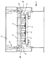
- Fig. 1 shows a device according to the invention generally designated by 10 for join a plurality of strips of materials 12a, 12b, 12c and 12d in cardboard corrugated.
- the strips 12a, 12b, 12c are composite strips formed each by a smooth strip and a wavy strip, while the 12d strip is just a smooth band.
- the device comprises a plurality of pressure 14, each being mounted to a frame 16 by means of a operating drive member 18 as well as support pins 20.
- a pressure plate 22 is mounted on the underside of the pressure 14 by means of support bars 24. Below the pressure plate 22 is mounted a back pressure plate 26 fixed to the frame 16, extending essentially in the horizontal direction and forming an essentially parallel pressure plate arrangement with the pressure plate 22 of the pressure unit 14.
- the pressure plate 22 and the back pressure plate 26 are each heatable arrangement, the heatable arrangement of the plate back pressure 26 not being described in more detail below.
- the backpressure plate 26 is heated preferably by a heat transfer fluid system.
- the pressure plate 22 is also heatable by a system carrying heat transfer fluid.
- the plate of pressure 22 is charged with heat-transfer fluid by supply lines and upper outlet 28 and 30 via fluid lines flexible 32.
- the strips of material 12a - 12d are guided by guide rollers 34 respectively guide elements 36 to a joining roller 38, where their sections with glue pressed against each other.
- the sticks to the contact points between the individual strips 12a - 12d is always liquid respectively wet, so that mutual adhesion bands is relatively small immediately behind the roll of junction 38, seen in a direction of advance A.
- Fig. 2 shows a detailed view of a pressure unit 14 according to the view in Fig. 1.
- the components already shown in Fig. 1 have the same references in FIG. 2.
- the pressure unit 14 is pivotally mounted to the support axis 20 by a support arm 40. Near the housing pivotable on the support axis 20, an operating lever 42 is fixed to the support arm 40 in orientation essentially perpendicular to the arm support 40.
- the actuating drive member 18 arranged as hydraulic force element is articulated to the operating lever 42 by through a hydraulic piston 44, a hydraulic cylinder 46 receiving the hydraulic piston 44 being articulated to the frame 16.
- a junction articulated to the terminal strip 24 is provided near the center of gravity S of it. Because of this measurement, the terminal strip 24 is always in an essentially horizontal position when moving of the support arm 40 around the support axis 20.
- the pressure plate 22 On the side of the terminal strip 24, which is remote from the support arm 40, the pressure plate 22 is mounted, the construction and connection of which to the terminal strip 24 are illustrated in the enlarged part VI.
- the plate of pressure 22 is mounted on the terminal strip 24 in such a way that its center of gravity lies in a plane essentially perpendicular to the direction of travel A, in which plane the center of gravity is S of the junction strip 24 as well as the axis of rotation of the junction articulated between the support arm 40 and the junction strip 24.
- a cover plate 48 is mounted on the upper face of the plate pressure 22 in such a way that it encloses an arch-shaped cavity 50 with the pressure plate 22.
- This cavity is accessible by pipes 52 and 52 ', which are connected to the upper supply line 28 and the upper outlet pipe 30 for the supply and exit, respectively, of heat transfer fluid by flexible fluid lines 32.32 '.
- pipes 52 and 52 ' are connected to the upper supply line 28 and the upper outlet pipe 30 for the supply and exit, respectively, of heat transfer fluid by flexible fluid lines 32.32 '.
- the guide faces 54 are provided, which allow the free entry of corrugated cardboard into the space between the pressure plate 22 and the back pressure plate 26 and its sliding in this space.
- an adjustment arrangement 56 is provided for at the articulated junction between the support arm 40 and the junction strip 24 allowing the resistance of the joint to be varied.
- the pressure plate 22 can be pivoted about the support axis 20 from the mutual contact position of pressure plate 22, corrugated cardboard P and back pressure plate 26 shown in FIG. 2 in a position removed from the carton corrugated P respectively of the back pressure plate 26 by the retraction of the hydraulic piston 44 in the hydraulic cylinder 46 and the associated pivoting of the operating lever 42 as well as of the support arm 40 connected with it.
- the pressure unit 14 thus allows positioning without gradations of the pressure plate 22 compared to the back pressure plate 26 and therefore a variation without gradations of pressure force and pressure applied to the cardboard wavy P.
- Fig. 3 shows a sectional view along line III-III in FIG. 1. Identical components have the same references as in Figs. 1 and 2. It is evident from FIG. 3, that four pressure units 14 1 , 14 2 , 14 3 , 14 4 are arranged on the support axis 20 one next to the other, an operating drive member 18 being respectively provided on the two axial ends of the axis of rotation 20 for the synchronous pivoting movement of the pressure units 14 1 , 14 2 , 14 3 , 14 4 around the support axis 20.
- the fluid supply line upper 28 supplying the four pressure units 14 1 - 14 4 with heat transfer fluid and being formed transverse to the direction of advance A oriented in the plane of FIG. 3.
- the supply line 28 passing transversely to the direction of advance A is itself connected to the supply lines 58, 58 ′ for the supply and for the outlet of heat transfer fluid.
- Fig. 4 shows a detailed perspective view of a pressure plate 22 provided with a cover plate 48.
- the direction of travel A is shown, in which a strip of corrugated cardboard spreads.
- the faces of guide 54 showing upwards.
- the cover plate 48 and pressure plate 22 are welded so waterproof. In the region inside the contour of the edges 60 of the plate cover 48, this and the pressure plate 22 are additionally joined by welding points 62.
- the cover plate 48 is lifted from the pressure plate 22 in the shape of an arch by an appropriate method of manufacturing, for example by the hydraulic expansion described above.
- FIG. 5 shows a section along line V-V in Fig. 4.
- the vault-shaped cavity 50 is formed between the plate of pressure 22 and the cover plate attached thereto.
- this cavity is crossed by the heat transfer fluid according to the arrows punctuated in FIG. 4.
- Fig. 6 shows two detailed views of alternative joining possibilities (Fig. 6a and 6b) of the pressure plate 22 and the terminal strip 24 corresponding to part VI in FIG. 2, the corrugated board having three wavy bands shown in Part VI being removed in Fig. 6.
- FIG. 6a a section of the junction strip 24 with several projections 64 on its face lower (of which only one shown in Fig. 6a), the projections corresponding to the arrangement on the one hand of the junction points 62 between the pressure plate 22 and cover plate 48.
- the terminal strip 24 is joined to the cover plate 48 and by the latter to the pressure plate 22 by the projection 64 at a welding point 62.
- the height h, by which the projection 64 projects from the face 66 of the terminal strip 24 is larger than the maximum bulge w of the cover plate 48, so that there has no place of mechanical contact and thus of thermal contact between the underside 66 of the terminal strip 24 and the cover plate 48 except on the undersides of the projections 64 in the area of the points of welding 62.
- Fig. 6a shows the thickness ratio between the thickness D of the pressure plate 22 and the thickness d of the cover plate 48.
- the thickness D of the pressure plate 22 amounts to at least twice the thickness d of the plate cover 48.
- Fig. 6b shows a second alternative according to the invention of the junction pressure plate 22 and terminal strip 24, components identical bearing the same references as in FIG. 6a.
- a threaded bolt 63 is welded to the cover plate 48 perpendicular to the pressure plate 22 at a welding point 62 on the side of the cover plate 48 showing towards the bar of junction 24.
- This threaded bolt 63 passes through a passage orifice 65 of a intermediate bar 67 resting on the crowns of the plate of cover 48.
- a hexagonal nut 69 is screwed on the section protruding from the threaded bolt 63, this nut pushing the intermediate bar 67 on the crowns of the cover plate 48.
- junction of the pressure plate 22 and the strip of junction 24 shown in FIG. 6b has the advantage that this junction is easy to do and to undo, so that the pressure plate 22 can be removed from the terminal strip 24 in a simple manner for reasons of assembly, troubleshooting and replacement.
- heat transfer is limited due to the relatively small total contact surface between the cover plate 48 and the intermediate bar 67.
- Fig. 7 shows various possibilities of a passage through several heatable pressure plates 22 arranged in the form of a matrix, the matrix arrangement 68 with lines R 1 - R 5 transverse to the direction of advance A and columns S 1 - S 4 in the direction of advance A being shown schematically in top view.
- the arrows inside the matrix arrangement 68 represent the directions of the passage of the heat transfer fluid through the pressure plates 22. Pressure plates not crossed by arrows are not charged with heat transfer fluid.
- Fig. 7a shows a matrix arrangement 68 composed of 20 pressure plates, the first three lines R 1 , R 2 , R 3 passing transversely to the direction of advance being charged with heat-transfer fluid and the lines R 4 , R 5 remaining without heating .
- the heat transfer fluid enters the pressure plate 22 1 arranged in the first place on the inlet side and gives heat there to the section of the strip of corrugated cardboard located at the below. Then the fluid flows from the pressure plate 22 1 into the pressure plate 22 2 , the heat-transfer fluid already having given up part of its thermal energy and thus having a lower temperature than when it entered the pressure plate 22 1 .
- the heat transfer fluid flows into the pressure plate 22 3 , the fluid having again a lower temperature when it passes through the plate pressure 22 3 only when entering the pressure plate 22 2 .
- the pressure plates of columns S 2 and S 3 are passed like those of column S 1 .
- a temperature gradient is thus obtained which decreases in the direction of advance A due to the generation of heat in the direction of flow of the fluid.
- Such coupling can be advantageous if the wet adhesive for bonding the strips of individual material to the strip of corrugated cardboard is to be returned from its liquid state to a state like a gel in the region of the first line R 1 of the plate pressure, which requires a strong supply of heat.
- the gelled adhesive is then cured, which requires a lower heat supply as a function of the rising distance from the inlet side end of the die arrangement, because the degree of hardening rises as a function of the rising distance from the end of entry side.
- Fig. 7b shows another coupling of the fluid system, to which heat transfer fluid has passed from the edge area (columns S 1 , S 4 ) of the matrix arrangement 68 transversely to the direction of advance A in the central area (columns S 2 , S 3 ) and left this zone.
- the coupling arrangement according to FIG. 7b leads to a heat supply profile transverse to the direction of advance A, a high heat flow being brought to the edge areas (columns S 1 , S 4 ) of the corrugated cardboard and the heat supply decreasing towards the center (columns S 2 , S 3 ) of the matrix arrangement 68.
- Such a coupling arrangement may for example be advantageous, if during the manufacture of wide strips of corrugated cardboard the degree of humidity in the edge areas exceeds that of the central area, so that a greater supply of heat is necessary in the areas of the edges to expel moisture.
Landscapes
- Engineering & Computer Science (AREA)
- Mechanical Engineering (AREA)
- Machines For Manufacturing Corrugated Board In Mechanical Paper-Making Processes (AREA)
- Laminated Bodies (AREA)
Applications Claiming Priority (2)
| Application Number | Priority Date | Filing Date | Title |
|---|---|---|---|
| DE19815863 | 1998-04-08 | ||
| DE19815863A DE19815863A1 (de) | 1998-04-08 | 1998-04-08 | Druckplatten-Anordnung zum Zusammenfügen einer Mehrzahl von jeweils wenigstens eine Glattbahn und/oder wenigstens eine Wellbahn umfassenden Materialbahnen zu einer Wellpappebahn |
Publications (2)
| Publication Number | Publication Date |
|---|---|
| EP0949064A2 true EP0949064A2 (de) | 1999-10-13 |
| EP0949064A3 EP0949064A3 (de) | 2001-12-05 |
Family
ID=7864062
Family Applications (1)
| Application Number | Title | Priority Date | Filing Date |
|---|---|---|---|
| EP99106722A Withdrawn EP0949064A3 (de) | 1998-04-08 | 1999-04-01 | Druckplattenanlage zum Verbinden von mehreren Materialbahnen - wovon jede mindestens eine flache Bahn und/oder mindestens eine gewölbte Bahn umfasst- zur Wellpappe |
Country Status (3)
| Country | Link |
|---|---|
| US (1) | US6257296B1 (de) |
| EP (1) | EP0949064A3 (de) |
| DE (1) | DE19815863A1 (de) |
Cited By (2)
| Publication number | Priority date | Publication date | Assignee | Title |
|---|---|---|---|---|
| US7291243B2 (en) | 2003-06-27 | 2007-11-06 | Fosber S.P.A. | Device for joining sheets of cardboard to form corrugated cardboard |
| CN111845050A (zh) * | 2020-07-06 | 2020-10-30 | 胡庭标 | 一种毛边纸切割印花装置 |
Families Citing this family (9)
| Publication number | Priority date | Publication date | Assignee | Title |
|---|---|---|---|---|
| JP2002120308A (ja) * | 2000-10-18 | 2002-04-23 | Isowa Corp | ダブルフェーサの荷重装置 |
| US6752074B2 (en) * | 2002-07-11 | 2004-06-22 | Corrugated Gear & Services, Inc. | Machine for manufacturing corrugated board with pressure applicator stabilizers |
| BE1015327A3 (nl) * | 2003-01-27 | 2005-01-11 | Corrutech Nv | Werkwijze en inrichting voor het vervaardigen van golfkarton of dergelijke. |
| TW200936469A (en) * | 2008-02-26 | 2009-09-01 | Tzu-Che Lin | Pushing device |
| ITMI20120325A1 (it) * | 2012-03-02 | 2013-09-03 | Bp Agnati S R L | Gruppo piani per un impianto per la produzione di cartone ondulato |
| US20150306836A1 (en) * | 2014-04-29 | 2015-10-29 | Greif Packaging Llc | Method and apparatus for manufacturing corrugated paperboard |
| US20200171813A1 (en) * | 2017-07-14 | 2020-06-04 | Landa Corporation Ltd. | Intermediate transfer member |
| CN113334863A (zh) * | 2021-05-31 | 2021-09-03 | 毛勇 | 一种瓦楞纸的连续压膜复合装置 |
| GB2619716A (en) * | 2022-06-13 | 2023-12-20 | Corridoor Ltd | Heating apparatus, corrugator system, and method |
Family Cites Families (12)
| Publication number | Priority date | Publication date | Assignee | Title |
|---|---|---|---|---|
| NL8600454A (nl) * | 1986-02-24 | 1987-09-16 | Cornelis Hendrikus Alsema | Verwarmingsinrichting voor lopende banen papier met sectiegewijs regelbare warmte toevoer. |
| DE3913555A1 (de) * | 1989-04-25 | 1990-10-31 | Hymmen Theodor Gmbh | Verfahren und vorrichtung zum beheizen des pressbandes einer presse |
| US5256240A (en) * | 1989-07-18 | 1993-10-26 | Simon Container Machinery Limited | Corrugating machine with a flexible vessel pressure applying means |
| US5244518A (en) * | 1990-11-02 | 1993-09-14 | Stickle Steam Specialties Co. Inc. | Corrugated board manufacturing apparatus and process including precise web moisture and temperature control |
| US5456783A (en) * | 1993-05-06 | 1995-10-10 | Interfic Developments Incorporated | Apparatus and method for enhancing heating uniformity for setting adhesive in corrugated paperboard manufacturing |
| US5495092A (en) * | 1994-06-07 | 1996-02-27 | Marquip, Inc. | Heating device for corrugated paperboard production |
| US5501762A (en) * | 1994-06-07 | 1996-03-26 | Marquip, Inc. | Hot plate for corrugated paperboard double facer |
| DE4437159A1 (de) * | 1994-10-18 | 1996-04-25 | Bhs Corr Masch & Anlagenbau | Heizvorrichtung für eine Wellpappe-Anlage |
| GB2299543B (en) * | 1995-04-06 | 1997-07-16 | Scm Container Mach Ltd | A heat transfer system |
| US5788803A (en) * | 1996-10-16 | 1998-08-04 | Interfic, Inc. | Corrugated paperboard manufacturing apparatus with controllable preheating |
| US6110095A (en) * | 1997-04-18 | 2000-08-29 | United Container Machinery Inc. | Apparatus for heating corrugated paperboard |
| US5915295A (en) * | 1997-10-15 | 1999-06-29 | Corrugated Gear And Services, Inc. | Machine for manufacturing corrugated board with heat exchangers on both sides of the board |
-
1998
- 1998-04-08 DE DE19815863A patent/DE19815863A1/de not_active Withdrawn
-
1999
- 1999-04-01 EP EP99106722A patent/EP0949064A3/de not_active Withdrawn
- 1999-04-05 US US09/286,556 patent/US6257296B1/en not_active Expired - Fee Related
Cited By (3)
| Publication number | Priority date | Publication date | Assignee | Title |
|---|---|---|---|---|
| US7291243B2 (en) | 2003-06-27 | 2007-11-06 | Fosber S.P.A. | Device for joining sheets of cardboard to form corrugated cardboard |
| CN111845050A (zh) * | 2020-07-06 | 2020-10-30 | 胡庭标 | 一种毛边纸切割印花装置 |
| CN111845050B (zh) * | 2020-07-06 | 2022-06-07 | 胡庭标 | 一种毛边纸切割印花装置 |
Also Published As
| Publication number | Publication date |
|---|---|
| EP0949064A3 (de) | 2001-12-05 |
| DE19815863A1 (de) | 1999-10-14 |
| US6257296B1 (en) | 2001-07-10 |
Similar Documents
| Publication | Publication Date | Title |
|---|---|---|
| EP0949064A2 (de) | Druckplattenanlage zum Verbinden von mehreren Materialbahnen - wovon jede mindestens eine flache Bahn und/oder mindestens eine gewölbte Bahn umfasst- zur Wellpappe | |
| EP1009625B1 (de) | Verfahren zum herstellen einer wabenförmigen struktur aus thermoplastischem kunststoff und vorrichtung zur durchführung des verfahrens | |
| WO1998016786A1 (fr) | Echangeur de chaleur, et faisceau d'echange de chaleur, ainsi que procedes de soudage et de realisation s'y rapportant | |
| FR2564032A1 (fr) | Dispositif de fermeture de moule | |
| FR2621460A1 (fr) | Appareil d'assemblage de pieces de textile plates | |
| EP1393904A2 (de) | Rotationspresse zum Anbringen von Bildern auf einem Substrat | |
| CA1171762A (fr) | Machine pour le sechage et le jointage de placages en continu et par contact | |
| EP0714728B1 (de) | Führungs- und Verlegungsvorrichtung für wenigstens zwei vorher angedockten Blechzuschnitten, insbesondere in einer Schweissanlage | |
| EP0038277B1 (de) | Maschine für die Herstellung eines Rohrprofils | |
| FR2658754A1 (fr) | Appareil a cellules de colle pour l'application de colle dans une unite d'impression de bande. | |
| EP2179917B1 (de) | Geformten und verstärkten Bahnen | |
| FR2576830A1 (fr) | Moule reglable pour la fabrication d'elements en beton, par exemple des escaliers | |
| FR2697036A1 (fr) | Dispositif pour la mise en Óoeuvre de revêtements de chaussée. | |
| EP0392912A2 (de) | Fluidtransportleitung | |
| CH599853A5 (de) | ||
| WO1990006841A1 (fr) | Procede de production de panneaux en continu et machine pour sa mise en ×uvre | |
| FR2602998A1 (fr) | Plateau chauffant ou refroidisseur pour dispositif de pressage, notamment pour une presse a deux bandes | |
| FR2826310A1 (fr) | Outillage pour le thermoformage d'une bande en matiere(s) synthetique(s) | |
| FR2822814A1 (fr) | Machine pour le collage d'une bande, procede de collage d'une bande pour la realisation d'une paroi isolante et etanche, et paroi isolante et etanche | |
| FR2638176A1 (fr) | Caisse de tete pour machine de fabrication de nappes de matiere en fibres, notamment de bandes de papier | |
| FR2965747A1 (fr) | Procede de fabrication d'un raidisseur en materiau composite | |
| FR2482170A1 (fr) | Machine de fabrication d'entrevous a revetement de beton de bois | |
| US3726747A (en) | Continuous-feed high-frequency gluing press | |
| FR2678209A1 (fr) | Machine de soudage en continu de les de matiere plastique. | |
| FR2640893A1 (de) |
Legal Events
| Date | Code | Title | Description |
|---|---|---|---|
| PUAI | Public reference made under article 153(3) epc to a published international application that has entered the european phase |
Free format text: ORIGINAL CODE: 0009012 |
|
| 17P | Request for examination filed |
Effective date: 19990401 |
|
| AK | Designated contracting states |
Kind code of ref document: A2 Designated state(s): AT BE CH CY DE DK ES FI FR GB GR IE IT LI LU MC NL PT SE Kind code of ref document: A2 Designated state(s): DE GB IT |
|
| AX | Request for extension of the european patent |
Free format text: AL;LT;LV;MK;RO;SI |
|
| PUAL | Search report despatched |
Free format text: ORIGINAL CODE: 0009013 |
|
| AK | Designated contracting states |
Kind code of ref document: A3 Designated state(s): AT BE CH CY DE DK ES FI FR GB GR IE IT LI LU MC NL PT SE |
|
| AX | Request for extension of the european patent |
Free format text: AL;LT;LV;MK;RO;SI |
|
| AKX | Designation fees paid |
Free format text: DE GB IT |
|
| RAP1 | Party data changed (applicant data changed or rights of an application transferred) |
Owner name: BHS CORRUGATED MASCHINEN-UND ANLAGENBAU GMBH |
|
| 17Q | First examination report despatched |
Effective date: 20031009 |
|
| STAA | Information on the status of an ep patent application or granted ep patent |
Free format text: STATUS: THE APPLICATION IS DEEMED TO BE WITHDRAWN |
|
| 18D | Application deemed to be withdrawn |
Effective date: 20040220 |