EP0949068A2 - Verfahren und Vorrichtung zum voneinander Abtrennen der Schichten von isolierten Röhren - Google Patents
Verfahren und Vorrichtung zum voneinander Abtrennen der Schichten von isolierten Röhren Download PDFInfo
- Publication number
- EP0949068A2 EP0949068A2 EP19990610027 EP99610027A EP0949068A2 EP 0949068 A2 EP0949068 A2 EP 0949068A2 EP 19990610027 EP19990610027 EP 19990610027 EP 99610027 A EP99610027 A EP 99610027A EP 0949068 A2 EP0949068 A2 EP 0949068A2
- Authority
- EP
- European Patent Office
- Prior art keywords
- pipe
- pressing
- inner tube
- gasses
- outer layer
- Prior art date
- Legal status (The legal status is an assumption and is not a legal conclusion. Google has not performed a legal analysis and makes no representation as to the accuracy of the status listed.)
- Granted
Links
- 238000000926 separation method Methods 0.000 title claims abstract description 61
- 238000003825 pressing Methods 0.000 claims abstract description 110
- 238000000034 method Methods 0.000 claims abstract description 79
- 239000000463 material Substances 0.000 claims abstract description 43
- 238000001914 filtration Methods 0.000 claims abstract description 19
- 238000005520 cutting process Methods 0.000 claims description 28
- 239000004604 Blowing Agent Substances 0.000 claims description 4
- 229910000831 Steel Inorganic materials 0.000 claims description 4
- 239000002184 metal Substances 0.000 claims description 4
- 229920002635 polyurethane Polymers 0.000 claims description 4
- 239000004814 polyurethane Substances 0.000 claims description 4
- 239000010959 steel Substances 0.000 claims description 4
- OKTJSMMVPCPJKN-UHFFFAOYSA-N Carbon Chemical compound [C] OKTJSMMVPCPJKN-UHFFFAOYSA-N 0.000 description 8
- 239000006260 foam Substances 0.000 description 5
- 238000004891 communication Methods 0.000 description 4
- 238000007790 scraping Methods 0.000 description 3
- 238000009423 ventilation Methods 0.000 description 3
- 229920001903 high density polyethylene Polymers 0.000 description 2
- 239000004700 high-density polyethylene Substances 0.000 description 2
- 229920000915 polyvinyl chloride Polymers 0.000 description 2
- 239000004800 polyvinyl chloride Substances 0.000 description 2
- 229910000851 Alloy steel Inorganic materials 0.000 description 1
- 238000009835 boiling Methods 0.000 description 1
- 238000002485 combustion reaction Methods 0.000 description 1
- 239000004020 conductor Substances 0.000 description 1
- 238000010276 construction Methods 0.000 description 1
- 238000009826 distribution Methods 0.000 description 1
- 230000005611 electricity Effects 0.000 description 1
- 230000007613 environmental effect Effects 0.000 description 1
- 238000005187 foaming Methods 0.000 description 1
- 239000004088 foaming agent Substances 0.000 description 1
- 230000006870 function Effects 0.000 description 1
- 230000005484 gravity Effects 0.000 description 1
- 238000010438 heat treatment Methods 0.000 description 1
- 238000009434 installation Methods 0.000 description 1
- 238000002955 isolation Methods 0.000 description 1
- 230000004048 modification Effects 0.000 description 1
- 238000012986 modification Methods 0.000 description 1
- 229920003023 plastic Polymers 0.000 description 1
- 239000004033 plastic Substances 0.000 description 1
- 229920000642 polymer Polymers 0.000 description 1
- 239000000843 powder Substances 0.000 description 1
- 238000004064 recycling Methods 0.000 description 1
- 238000005096 rolling process Methods 0.000 description 1
- 230000003068 static effect Effects 0.000 description 1
Images


Classifications
-
- B—PERFORMING OPERATIONS; TRANSPORTING
- B29—WORKING OF PLASTICS; WORKING OF SUBSTANCES IN A PLASTIC STATE IN GENERAL
- B29C—SHAPING OR JOINING OF PLASTICS; SHAPING OF MATERIAL IN A PLASTIC STATE, NOT OTHERWISE PROVIDED FOR; AFTER-TREATMENT OF THE SHAPED PRODUCTS, e.g. REPAIRING
- B29C63/00—Lining or sheathing, i.e. applying preformed layers or sheathings of plastics; Apparatus therefor
- B29C63/0004—Component parts, details or accessories; Auxiliary operations
- B29C63/0013—Removing old coatings
-
- B—PERFORMING OPERATIONS; TRANSPORTING
- B29—WORKING OF PLASTICS; WORKING OF SUBSTANCES IN A PLASTIC STATE IN GENERAL
- B29B—PREPARATION OR PRETREATMENT OF THE MATERIAL TO BE SHAPED; MAKING GRANULES OR PREFORMS; RECOVERY OF PLASTICS OR OTHER CONSTITUENTS OF WASTE MATERIAL CONTAINING PLASTICS
- B29B17/00—Recovery of plastics or other constituents of waste material containing plastics
- B29B17/02—Separating plastics from other materials
-
- B—PERFORMING OPERATIONS; TRANSPORTING
- B29—WORKING OF PLASTICS; WORKING OF SUBSTANCES IN A PLASTIC STATE IN GENERAL
- B29B—PREPARATION OR PRETREATMENT OF THE MATERIAL TO BE SHAPED; MAKING GRANULES OR PREFORMS; RECOVERY OF PLASTICS OR OTHER CONSTITUENTS OF WASTE MATERIAL CONTAINING PLASTICS
- B29B17/00—Recovery of plastics or other constituents of waste material containing plastics
- B29B17/02—Separating plastics from other materials
- B29B2017/0203—Separating plastics from plastics
-
- B—PERFORMING OPERATIONS; TRANSPORTING
- B29—WORKING OF PLASTICS; WORKING OF SUBSTANCES IN A PLASTIC STATE IN GENERAL
- B29K—INDEXING SCHEME ASSOCIATED WITH SUBCLASSES B29B, B29C OR B29D, RELATING TO MOULDING MATERIALS OR TO MATERIALS FOR MOULDS, REINFORCEMENTS, FILLERS OR PREFORMED PARTS, e.g. INSERTS
- B29K2023/00—Use of polyalkenes or derivatives thereof as moulding material
- B29K2023/04—Polymers of ethylene
- B29K2023/06—PE, i.e. polyethylene
-
- B—PERFORMING OPERATIONS; TRANSPORTING
- B29—WORKING OF PLASTICS; WORKING OF SUBSTANCES IN A PLASTIC STATE IN GENERAL
- B29K—INDEXING SCHEME ASSOCIATED WITH SUBCLASSES B29B, B29C OR B29D, RELATING TO MOULDING MATERIALS OR TO MATERIALS FOR MOULDS, REINFORCEMENTS, FILLERS OR PREFORMED PARTS, e.g. INSERTS
- B29K2027/00—Use of polyvinylhalogenides or derivatives thereof as moulding material
- B29K2027/06—PVC, i.e. polyvinylchloride
-
- B—PERFORMING OPERATIONS; TRANSPORTING
- B29—WORKING OF PLASTICS; WORKING OF SUBSTANCES IN A PLASTIC STATE IN GENERAL
- B29K—INDEXING SCHEME ASSOCIATED WITH SUBCLASSES B29B, B29C OR B29D, RELATING TO MOULDING MATERIALS OR TO MATERIALS FOR MOULDS, REINFORCEMENTS, FILLERS OR PREFORMED PARTS, e.g. INSERTS
- B29K2075/00—Use of PU, i.e. polyureas or polyurethanes or derivatives thereof, as moulding material
-
- B—PERFORMING OPERATIONS; TRANSPORTING
- B29—WORKING OF PLASTICS; WORKING OF SUBSTANCES IN A PLASTIC STATE IN GENERAL
- B29K—INDEXING SCHEME ASSOCIATED WITH SUBCLASSES B29B, B29C OR B29D, RELATING TO MOULDING MATERIALS OR TO MATERIALS FOR MOULDS, REINFORCEMENTS, FILLERS OR PREFORMED PARTS, e.g. INSERTS
- B29K2105/00—Condition, form or state of moulded material or of the material to be shaped
- B29K2105/04—Condition, form or state of moulded material or of the material to be shaped cellular or porous
-
- B—PERFORMING OPERATIONS; TRANSPORTING
- B29—WORKING OF PLASTICS; WORKING OF SUBSTANCES IN A PLASTIC STATE IN GENERAL
- B29K—INDEXING SCHEME ASSOCIATED WITH SUBCLASSES B29B, B29C OR B29D, RELATING TO MOULDING MATERIALS OR TO MATERIALS FOR MOULDS, REINFORCEMENTS, FILLERS OR PREFORMED PARTS, e.g. INSERTS
- B29K2705/00—Use of metals, their alloys or their compounds, for preformed parts, e.g. for inserts
-
- B—PERFORMING OPERATIONS; TRANSPORTING
- B29—WORKING OF PLASTICS; WORKING OF SUBSTANCES IN A PLASTIC STATE IN GENERAL
- B29L—INDEXING SCHEME ASSOCIATED WITH SUBCLASS B29C, RELATING TO PARTICULAR ARTICLES
- B29L2009/00—Layered products
-
- B—PERFORMING OPERATIONS; TRANSPORTING
- B29—WORKING OF PLASTICS; WORKING OF SUBSTANCES IN A PLASTIC STATE IN GENERAL
- B29L—INDEXING SCHEME ASSOCIATED WITH SUBCLASS B29C, RELATING TO PARTICULAR ARTICLES
- B29L2023/00—Tubular articles
- B29L2023/22—Tubes or pipes, i.e. rigid
- B29L2023/225—Insulated
-
- Y—GENERAL TAGGING OF NEW TECHNOLOGICAL DEVELOPMENTS; GENERAL TAGGING OF CROSS-SECTIONAL TECHNOLOGIES SPANNING OVER SEVERAL SECTIONS OF THE IPC; TECHNICAL SUBJECTS COVERED BY FORMER USPC CROSS-REFERENCE ART COLLECTIONS [XRACs] AND DIGESTS
- Y02—TECHNOLOGIES OR APPLICATIONS FOR MITIGATION OR ADAPTATION AGAINST CLIMATE CHANGE
- Y02W—CLIMATE CHANGE MITIGATION TECHNOLOGIES RELATED TO WASTEWATER TREATMENT OR WASTE MANAGEMENT
- Y02W30/00—Technologies for solid waste management
- Y02W30/50—Reuse, recycling or recovery technologies
- Y02W30/62—Plastics recycling; Rubber recycling
Definitions
- the invention concerns an automated method and an apparatus for separation of pipes comprising a inner tube and an outer layer by pressing the pipe into deformation.
- the same apparatus may be used for pipes of different diameters as well as bend pipes.
- the invention concerns in particular a method and an apparatus for separation of pipes of which the outer layer is made from a foamed material comprising CFC gasses, especially R11 and R12. A substantial part of the CFC gasses is released during the pressing process and is removed by suction and captured in a filtering means adapted for absorbing CFC gasses.
- the pipes in question comprise an inner tube, usually made from a metal such as steel and one or more outer layers of which at least one is an isolating layer, usually made from a foamed material, and optionally a sheath, usually made from a hard plastic material such as polyvinyl chloride polymer (PVC) or high density polyethylene (hd-PE).
- PVC polyvinyl chloride polymer
- hd-PE high density polyethylene
- the pipes and/or the inner tubes may have any cross-sectional shape such as round, square, triangular, oval, etc., but the most common shape is round.
- the foamed material may involve a problem when the components of the pipes are separated.
- the most common foaming agent that was used until about 1990 is CFC gasses, known as R11 and R12. These gasses are contained within the foam and tests show that a large part of the gasses will be released during a separation process. This presents a problem for separation processes, since the release of CFC gasses to the atmosphere is unwanted for environmental reasons.
- Another problem for the process of separating pipes is that the pipes often have bends and/or dents due to the installation they have formed part of, or due to the dismantling process. Furthermore, the pipes are often connected to T-pieces, elbows, muffs and/or expansion joints, that are time-consuming to remove manually from the pipes. Therefore, the method and apparatus for the separating process have to be flexible to the shape of the pipes. Further, the pipes to be disposed are often of different diameters, both with regard to the outer diameter of the pipe and the diameter of the inner tube for which reason it is highly desirable for a method and an apparatus for separation of pipes that they are flexible to these parameters.
- the pipes to be separated comes in different length and a method and an apparatus for separation of pipes should preferably be able to handle pipes of various lengths.
- Known separation methods comprises manual separation where the isolating layer is scraped from the inner tube manually. Manual separation is mostly used when the inner tube is being reused and the method is highly labour-consuming. Another method is shredding in which the pipe is broken down into small pieces that subsequently are sorted but it is very difficult to prevent released gasses from entering the atmosphere in this process.
- a third known method is to force the pipe by hydraulic means through a die that fits with the outer surface of inner tube so that the outer layer is scraped from the inner tube.
- a special die have to be supplied for each diameter of the inner tubes and the method can only be applied to substantially straight pipes without bends or dents.
- the third known method may only for practical reasons be applied to pipes with a maximum length of approximately three meters.
- gasses such as, e.g., CFC gasses
- gasses such as, e.g., CFC gasses
- the invention concerns a method of separating a pipe comprising an inner tube and at least one outer layer comprising the steps of
- the mechanical properties of the inner tube may be that it is made from a plastically deformable material, such as one of a number of steel alloys, and may be pressed into a substantially flat member whereas the outer layer may be made from a hard and brittle material, such as polyurethane, that will break into pieces during the pressing process. If the outer layer comprises a foamed material, then most of the cells of this foamed material will break during the pressing process and the gas that have been used as a blowing agent and is comprised within the cells are released from the foamed material as the foamed material is crushed during the pressing step.
- the method is applied to pipes wherein the inner fube is a metal tube, such as a steel tube.
- the inner tube is in the pressing step permanently deformed into a substantially flat member.
- the required pressing force depends on the type and diameter of the tube and of the length of the tube positioned between the pressing surfaces. This length may be from 0.25 meter to 3 or 4 meters, preferably between 0.5 and 2 meters and most preferred between 1 and 1.5 meters.
- the applied pressing force is for a length of tube of 1 to 1.5 meters from 400 to 900 kN (kilo Newton), preferably from 600-700 kN.
- the process may, for tubes having a hard sheath, prior to the pressing step comprise a step in which the sheath is opened with one, two or more longitudinal cuts so as to ease the pressing process, allow gasses to escape from the foam and the ease the separation of the sheath part from the pipe and foam parts after the pressing process.
- the cuts may be applied manually or automatically by means of knives, circular saws, etc.
- the method may further according to the invention comprise the step of applying suction to the region where the separation process is performed so as to remove a substantial part of gasses that are released during the process.
- the air that is sucked from the region where the separation process is performed is in a preferred embodiment according to the invention passed through a filtering means so as to capture a substantial part of the gasses, that are released from the process and which are removed by suction, in the filtering means, so as to prevent the gasses from contaminating the environment.
- the method may also according to the invention, subsequently to the pressing step comprise the steps of
- the method may also according to the invention further comprise the step of loosening remaining parts of the at least one outer layer of the pipe from the inner tube by applying loosening means to the pipe.
- the loosening means may comprise two scrapers each comprising an edge and such loosening means are applied to the pipe by placing the edges of the scrapers on each side of the deformed inner tube abutting the flat tube sides where after the tube and the scrapers are moved relatively to each other.
- the loosening means may comprise brushes that may be rotated and such loosening means are applied to the pipe by rotating the brushes while these are in contact with the part of the pipe that have been deformed so as to remove remaining parts of the at least one outer layer from the inner tube.
- the method according to the invention may preferably be performed on pipes of which the outer layer of the pipe is at least partly made from a foamed material.
- the foamed material may comprise polyurethane.
- the foamed material may further comprise CFC gasses which have been used as blowing agent so that the gasses that may be released during the separation process comprises CFC gasses.
- the invention also concerns an apparatus for separating pipes comprising an inner tube and at least one outer layer, the apparatus comprises
- the first and second pressing member are preferably of such a rigid construction that the pressing surfaces are only slightly deformed during the pressing process.
- the pressing surfaces may be of various shapes so that the apparatus is suitable for treating objects of various shapes and sizes and with bends and dents.
- the pressing surfaces are in a preferred embodiment of the invention substantially flat and parallel to each other, at least during the pressing process.
- the pressing surfaces may be oriented in any direction during the pressing process, horizontally, vertically or in between.
- the pressing surfaces are substantially horizontal, so that the tube may be supported by the lower of the surfaces before the pressing process.
- tilted or vertical surfaces have the advantage that debris from the pressing process may be removed from between the pressing surfaces by the force of gravity.
- the means for moving at least one of the pressing members towards the other pressing member or for moving both pressing members towards each other may be any suitable mechanical means such as hydraulic pistons, pneumatic piston, spindles, etc.
- the suction means may be one or more ventilators, air pumps, blowers, etc.
- the apparatus may further according to the invention comprise a filtering means connected to the outlet of the suction means, the filtering means being suitable for capturing a substantial part of the gasses that may be released during the separation process.
- the filtering means may be a activated charcoal filter or another suitable filter or it may comprise means for condensing the gasses.
- the filtering means are in a preferred embodiment of the invention suitable for capturing CFC gasses.
- the apparatus comprises in a further preferred embodiment according to the invention a housing enclosing the pressing members and to which the intake of the suction means is connected so as to increase the efficiency of the process of removing a substantial part of the gasses, that may be released during the separation process from the region around the pressing surfaces.
- the apparatus may also in a preferred embodiment of the invention comprise feeding means adapted for automatically feeding the pipe in between the pressing surfaces.
- the feeding means may be a conveyor with an endless belt or chain that engages the pipe, it may comprise a number of cylinders or balls on which the pipe rolls and drive means for driving the pipe towards the separation region, etc.
- the apparatus may in a preferred embodiment of the invention comprise cutting means suitable for separating a pressed part of a pipe from a non-pressed part of a pipe.
- the cutting means may comprise a part with a straight cutting edge and a part with an inclined cutting edge so that the only a part of the inclined cutting edge at a time is engaging the pipe.
- the apparatus may according to the invention further comprise loosening means suitable for removing parts of the outer layer of the pipe from the inner tube after the pressing process.
- the loosening means may comprise two scrapers each with an edge, means for placing the two scrapers one on each side of and abutting the pressed part of the inner tube and means for moving the scrapers and the inner tube relatively to each other.
- the loosening means comprises brushes, means for rotating the brushes, means for placing the brushes on each side of the pressed part of the inner tube and means for moving the brushes and the inner tube relatively to each other.
- the shown device comprises a conveyor unit 1 for feeding the pipes into the separation region 2.
- the conveyor unit 1 comprises an endless chain specially formed for engaging with and moving the pipes and a drive means for driving the endless chain.
- the apparatus further comprises a first, stationary pressing member 3 having a first pressing surface 4, a second, movable pressing member 5 having a second pressing surface 6 and means comprising hydraulic pistons 7 for moving the second pressing member 5.
- the first 3 and second 5 pressing members and the hydraulic pistons 7 are comprised within a housing 8 that is connected with a ventilation pipe 9 to a suction means comprising a ventilator 10, the ventilation pipe 9 being connected to the intake of the ventilator 10.
- the housing 8 is closed on the top and on the sides and is only provided with openings for entering 11 and exiting the pipes into and from the separation region 2.
- the function of the housing 8 is to enhance the efficiency of removing gasses being released during the separation process from the separation region 2 with the ventilator 10.
- the openings of the housing 8 allow air from the outside to entrain into the housing 8 and create an air stream in the separation region 2 and out through the ventilation pipe 9 and the ventilator 10 so that gasses released during the separation process are carried away or sucked from the separation region 2.
- the hydraulic pistons 7 apply a pressing force of 65 tonnes, equivalent to about 650 kN.
- the shown embodiment of the invention is designed for pipes with a diameter of the inner tube of 200-800 mm and an outer diameter of the pipe with isolation and sheath of 300-1200 mm, in particular two types of pipes with diameters of the inner tube of 273 mm and 610 mm, respectively, and an outer diameter of 400 mm and 800 mm, respectively, the two types of pipes conforming to the Danish standards DN 250 and DN 608.
- the ventilator 10 has a capacity of 1300 cubic meter air per hour, and the outlet of the ventilator 10 is connected to filtering means 16 comprising activated charcoal filters that are suitable for capturing a substantial part of CFC gasses that may be release during the separation process and are transported from the separation region 2 via the ventilator 10.
- the filtering means comprise two activated charcoal filters connected in series, each comprising 500 kg activated charcoal being able to absorb about 14 kg of CFC gasses.
- the apparatus further comprises cutting means comprising a stationary first part 12, a movable second part 13 and means for moving the movable second part 13, said means comprising a hydraulic piston 14.
- the cutting means are placed adjacent to an opening of the housing 8 in substantially the same horizontal plane as the first pressing surface 4 opposite to the conveyor unit 1 so that the part of the pipe that have been pressed after the separation process may be moved out between the first part 12 and the second part 14 of the cutting means so that the cutting means may separate the pressed parts of the pipe from the non-pressed parts of the pipe.
- the apparatus also comprises conveyors 15, 17 for transporting the separated parts of the pipes away from the separation region 2 and the cutting means 12, 13 to a sorting station where the parts are sorted into containing means 18 for metal parts from the inner tube, foamed material, sheath material and optionally other materials, respectively.
- the apparatus may also comprise loosening means for loosening remaining parts of the foamed material from the inner tube after the separation process.
- loosening means may be placed inside the housing 8 in case the foamed material still contains gasses that may be released during the loosening process so that these gasses may be removed by means of the ventilator 10.
- the loosening means may comprise scrapers that are moved along each side of the inner tube that is substantially flat due to the pressing process.
- the scrapers may be two scraper members each having a scraping edge of at least the same width of the inner tube and adapted for scraping each one side of the inner tube.
- the scraper members may alternatively each comprise a multitude of spring-loaded fingers placed closely adjacent to each other, each finger having a scraping edge of a more narrow width that the inner tube so as to make the scrapers more flexible to unevenness of the inner tube.
- the loosening means may in another embodiment of the invention comprise brushes that may be rotated by rotation means and are moved along the two sides of the inner tube so as to loosen parts of the foamed material that stick to the inner pipe.
- the brushes may rotate about axes that are substantially perpendicular to the plane of the flat inner tube or they may rotate about axes that are parallel to the plane of the flat inner tube.
- the apparatus may also comprise secondary separation means adapted for separating the foamed material from the sheath material to which it may stick after the separation process.
- This secondary separation process may be performed inside the housing 8 in case the foamed material still comprises gasses that may be released during the secondary separation process so that these gasses may be removed by the ventilator 10, or the process may be performed somewhere else, such as, e.g., at the sorting station.
- the secondary separation means may comprise scrapers or brushes similarly to the loosening means.
- the secondary separation means comprises two rotatable cylinders between which the sheath material is rolled so as to loosen the foamed material that may stick to the sheath material.
- the apparatus Preferably, most of or all parts of the apparatus are connected to earth with conductors so as to prevent static electricity on the parts.
- This arrangement is preferred since the foaming materials and optionally also the sheath materials often are highly inflammable for which reason the apparatus preferably also is equipped with fire fighting and/or fire extinguishing means such as powder extinguishers.
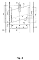
- the cutting means are shown in Fig. 3. They comprise a stationary first part 12 with a first cutting edge 19, a movable second part 13 with a second cutting edge 20 and a hydraulic piston 14 for moving the movable second part 13.
- the first cutting edge 19 is substantially horizontal whereas the second cutting edge 20 is inclined so that only a part of the inclined cutting edge 20 at a time is engaging with the pipe so as to make the cutting process more efficient and to reduce the demand for cutting force delivered by the hydraulic piston 14.
- the movable second part 13 is equipped with means 21 for connecting the second part 13 to the hydraulic piston 14.
- the stationary first part 12 is mounted on vertical beams 22 that constitute a part of a frame.
- the movable second part 13 is slidably connected to the vertical beams 22.
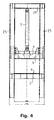
- the pressing members are shown in Fig. 4.
- the first, stationary pressing member 3 has a first pressing surface 4 and the second, movable pressing member 5 has a second pressing surface 6.
- the stationary first pressing member 3 is mounted on vertical beams 23 that constitute a part of a frame.
- the movable second pressing member 5 is mounted slidably on the vertical beams 23 and is driven in the vertical direction by hydraulic pistons 7.
- the lower ends of the hydraulic pistons 7 are connected to the second pressing member 5 and the upper ends of the hydraulic pistons 7 are connected to a horizontal beam 24 that also constitutes a part of the frame.
- the whole process of separating the pipes may be controlled manually, but the apparatus comprises in a preferred embodiment programmable control means for controlling the process, the control means comprising a programmable control part comprising a micro processor, a computer readable memory and a computer software program adapted for controlling the process, such as a Personal Computer with a suitable software program or a programmed PLC.
- the control means may further comprise a number of sensors for detecting the position of the pipe at various places, data communication means adapted for providing communication between the control part and motors, switches and/or valves that are used to regulate and control the various steps of the processes and/or data communication means adapted for providing communication between the control part and the sensors.
- the method according to the invention of separating a pipe with the apparatus is described in the following.
- the pipe is placed on the conveyor unit 1 which moves a part, such as approximately 1.5 meters, into the separation region 2 that is located between the two pressing members 3, 5 each having a pressing surface 4, 6, respectively.
- the second pressing member 5 is moved towards the first pressing member 3 by means of the hydraulic pistons 7 until both pressing surfaces 4, 6 are in contact with the pipe.
- the pressing process begins in which the second pressing member 5 is pressed towards the first pressing member 3 by means of the hydraulic pistons 7 with a force of a magnitude sufficient to deform the pipe.
- the inner tube, usually made from steel, of the pipe is during the pressing process permanently plastically deformed into a substantially flat member of which the original opening in the middle is substantially closed and the flat member obtains two substantially flat and substantially parallel sides.
- the outer, isolating layer of the pipe made from a foamed material is a brittle material that will break into smaller pieces and at least partly be crushed during the pressing process, whereby the outer layer is at least partially separated from the inner tube.
- the cells of the foamed material will, when the material is crushed, release their content of gasses that have been used as a blowing agent, such as CFC gasses. Therefore, the process is preferably performed at a temperature above to boiling temperature of the gasses so as to remove as much gas as possible from the foamed material during the pressing process.
- the ventilator is activated during the pressing process so that gasses, such as CFC gasses, that may be released from the foamed material during the pressing process is sucked from the separation region 2 and out through the filtering means 16 in which a substantial part of the released gasses are captured.
- gasses such as CFC gasses
- the part of the tube that have been pressed is moved out of the separation region 2 and through the two parts 12, 13 of the cutting means as the next part of the pipe is placed in the separation region 2.
- the hydraulic piston 14 for moving the second part 13 of the cutting means is activated and the pressed part of the pipe is cut from the remaining, non-pressed part of the pipe and is moved by means of the conveyors 16, 17 to the sorting station.
- the sheath that the pipe may be equipped with on the outer side of the outer layer will often be broken into smaller pieces during the pressing process. However, the sheath is easily separated from the outer layer and the inner tube after the cutting step even if the sheath is still in one piece.
- the sheath may optionally be subjected to a secondary separation process, e.g. by rolling the sheath between two cylinders, in order to loosen parts of the outer layer that may stick to the sheath.
- cutting means are provided for tubes having a hard sheath, so that the sheath prior to the pressing step is opened with one or two longitudinal cuts so as to ease the pressing process, allow gasses to escape from the foam and the ease the separation of the sheath part from the pipe and foam parts after the pressing process.
- the cuts may be applied manually or automatically by means of knives, circular saws, etc.
- loosening means are further applied to the inner tube for loosening parts of the outer layer that may stick to the inner tube after the pressing process have been performed.
- the foamed material may after the sorting process be recycled or disposed in a number of ways, e.g. by being combusted in a combustion plant at such high temperature that a remaining content of CFC gasses are destroyed.
- the gasses contained in the filtering means may be recovered or destroyed together with the filtering means.
Landscapes
- Engineering & Computer Science (AREA)
- Environmental & Geological Engineering (AREA)
- Mechanical Engineering (AREA)
- Manufacturing & Machinery (AREA)
- Processing Of Solid Wastes (AREA)
- Processing And Handling Of Plastics And Other Materials For Molding In General (AREA)
- Separation Using Semi-Permeable Membranes (AREA)
- Pipeline Systems (AREA)
Applications Claiming Priority (2)
| Application Number | Priority Date | Filing Date | Title |
|---|---|---|---|
| DK51398 | 1998-04-08 | ||
| DK051398 | 1998-04-08 |
Publications (3)
| Publication Number | Publication Date |
|---|---|
| EP0949068A2 true EP0949068A2 (de) | 1999-10-13 |
| EP0949068A3 EP0949068A3 (de) | 2000-05-31 |
| EP0949068B1 EP0949068B1 (de) | 2006-12-27 |
Family
ID=8094411
Family Applications (1)
| Application Number | Title | Priority Date | Filing Date |
|---|---|---|---|
| EP19990610027 Expired - Lifetime EP0949068B1 (de) | 1998-04-08 | 1999-04-07 | Verfahren und Vorrichtung zum voneinander Abtrennen der Schichten von isolierten Röhren |
Country Status (4)
| Country | Link |
|---|---|
| EP (1) | EP0949068B1 (de) |
| AT (1) | ATE349318T1 (de) |
| DE (1) | DE69934535T2 (de) |
| DK (1) | DK0949068T3 (de) |
Cited By (5)
| Publication number | Priority date | Publication date | Assignee | Title |
|---|---|---|---|---|
| EP1174656A1 (de) * | 2000-07-18 | 2002-01-23 | GLI International | Verfahren zum Lösen einer Schutzhülle von einer metallischen Struktur und seine Anwendung |
| WO2002040238A1 (en) * | 2000-11-16 | 2002-05-23 | Matsushita Electric Industrial Co., Ltd. | Foam resin, method of collecting foam gas, and method of disassembling refrigerator |
| US6836947B2 (en) | 2000-08-30 | 2005-01-04 | Matsushita Electric Industrial Co., Ltd. | Method of dismantling air conditioner |
| US6944926B2 (en) | 2000-07-14 | 2005-09-20 | Matsushita Electric Industrial Co., Ltd. | Method for disassembling refrigerator, compressing device, and device for disassembling the same |
| WO2024205432A1 (en) | 2023-03-25 | 2024-10-03 | Kan Spółka Z Ograniczoną Odpowiedzialnością | A multilayer pipe recycling method and a multilayer pipe recycling device |
Families Citing this family (2)
| Publication number | Priority date | Publication date | Assignee | Title |
|---|---|---|---|---|
| CN109092968B (zh) * | 2018-08-03 | 2020-05-01 | 珠海菲高科技股份有限公司 | 自动冲压系统 |
| CN112549408A (zh) * | 2020-11-24 | 2021-03-26 | 湖南昌泰金属设备制造有限公司 | 一种用于汽车零部件的无机胶凝材料滚压成型的模具 |
Family Cites Families (4)
| Publication number | Priority date | Publication date | Assignee | Title |
|---|---|---|---|---|
| DE3905610C1 (de) * | 1989-02-23 | 1990-09-13 | Toensmeier Containerdienst Gmbh, 4952 Porta Westfalica, De | |
| NL8902696A (nl) * | 1989-11-01 | 1991-06-03 | Gen Electric | Werkwijze en inrichting voor het scheiden van kunststofschuim van met kunststofschuim beklede stijve dunwandige voorwerpen. |
| DE4133592A1 (de) * | 1991-10-11 | 1993-04-15 | Achenbach Cryotechnik Gmbh | Verfahren und anlage zum trennen der kunststoffbestandteile und der metallbestandteile von langgestreckten und flaechigen bauelementen aus metall/kunststoff-verbundwerkstoffen |
| BE1007472A4 (fr) * | 1993-09-08 | 1995-07-11 | Draka Polva Bv | Procede et dispositif de traitement d'articles en matiere plastique, et installation pour la recuperation selective de matieres plastiques. |
-
1999
- 1999-04-07 EP EP19990610027 patent/EP0949068B1/de not_active Expired - Lifetime
- 1999-04-07 DE DE1999634535 patent/DE69934535T2/de not_active Expired - Lifetime
- 1999-04-07 AT AT99610027T patent/ATE349318T1/de not_active IP Right Cessation
- 1999-04-07 DK DK99610027T patent/DK0949068T3/da active
Non-Patent Citations (1)
| Title |
|---|
| None |
Cited By (7)
| Publication number | Priority date | Publication date | Assignee | Title |
|---|---|---|---|---|
| US6944926B2 (en) | 2000-07-14 | 2005-09-20 | Matsushita Electric Industrial Co., Ltd. | Method for disassembling refrigerator, compressing device, and device for disassembling the same |
| EP1174656A1 (de) * | 2000-07-18 | 2002-01-23 | GLI International | Verfahren zum Lösen einer Schutzhülle von einer metallischen Struktur und seine Anwendung |
| FR2812070A1 (fr) * | 2000-07-18 | 2002-01-25 | Gli Internat | Procede pour decoller d'une structure metallique un habillage protecteur plastique et application de ce procede |
| US6836947B2 (en) | 2000-08-30 | 2005-01-04 | Matsushita Electric Industrial Co., Ltd. | Method of dismantling air conditioner |
| WO2002040238A1 (en) * | 2000-11-16 | 2002-05-23 | Matsushita Electric Industrial Co., Ltd. | Foam resin, method of collecting foam gas, and method of disassembling refrigerator |
| US6938318B2 (en) | 2000-11-16 | 2005-09-06 | Matsushita Electric Industrial Co., Ltd. | Method for collecting a foam resin from a housing of a refrigerator |
| WO2024205432A1 (en) | 2023-03-25 | 2024-10-03 | Kan Spółka Z Ograniczoną Odpowiedzialnością | A multilayer pipe recycling method and a multilayer pipe recycling device |
Also Published As
| Publication number | Publication date |
|---|---|
| DE69934535D1 (de) | 2007-02-08 |
| EP0949068A3 (de) | 2000-05-31 |
| DK0949068T3 (da) | 2007-03-12 |
| DE69934535T2 (de) | 2007-10-25 |
| ATE349318T1 (de) | 2007-01-15 |
| EP0949068B1 (de) | 2006-12-27 |
Similar Documents
| Publication | Publication Date | Title |
|---|---|---|
| US4813614A (en) | Method and apparatus for treating waste products to recover the components thereof | |
| DE3941742C2 (de) | ||
| EP0949068B1 (de) | Verfahren und Vorrichtung zum voneinander Abtrennen der Schichten von isolierten Röhren | |
| JP5933449B2 (ja) | Lcdディスプレイからの有害物質の除去 | |
| JP2002144344A (ja) | 発泡樹脂及び発泡ガスの回収方法と、冷蔵庫の解体方法 | |
| KR101935590B1 (ko) | 스티로폼 파쇄장치 | |
| EP0442113A2 (de) | Verfahren und Vorrichtung zur Beseitigung von Kühlgeräten | |
| WO2002038295A1 (en) | An installation for recovering gases which damage the environment | |
| FR3023496A1 (fr) | Dispositif de preparation de recipients d’aerosols pour leur elimination ou leur recyclage et installation comprenant un tel dispositif. | |
| KR0162130B1 (ko) | 쓰레기를 이용한 고체연료의 제조방법 및 그 제조장치 | |
| EP0458172B1 (de) | Verfahren zur Beseitigung von Treibmitteln aus Kunststoffschäumen sowie Vorrichtung hierfür | |
| US5443567A (en) | Tire carcass shredding method and apparatus | |
| CN100528509C (zh) | 破坏装置、发泡气体回收装置及发泡气体分离回收系统 | |
| US6732416B1 (en) | Refrigerator recycling method and system | |
| CN117039232A (zh) | 一种环保型电芯拆解处理设备 | |
| DE8914957U1 (de) | Vorrichtung zum Entsorgen von teilentsorgten Kühlgeräten | |
| CA2084070A1 (en) | Process and device for disposing of packings | |
| US6637098B2 (en) | Waste fluorescent lamp dismantling apparatus | |
| JP2002260465A (ja) | 電線ケーブル外装材の合成樹脂材と金属材の剥離・分離方法及び装置 | |
| NO340645B1 (no) | Apparat og framgangsmåte for resirkulering av bygningsmaterialer | |
| JP4740980B2 (ja) | 袋詰め廃アスベストの圧縮梱包処理装置 | |
| US20060200964A1 (en) | Appliance recycling process | |
| JP3451044B2 (ja) | ウレタン発泡断熱材の処理方法および処理装置 | |
| CH700480A2 (it) | Disgregatore di manufatti accoppiati con altri materiali, materiali scomposti contenuti cosi' ottenuti e prodotti da essi derivati. | |
| KR100522009B1 (ko) | 폐 오일필터의 분리장치 |
Legal Events
| Date | Code | Title | Description |
|---|---|---|---|
| PUAI | Public reference made under article 153(3) epc to a published international application that has entered the european phase |
Free format text: ORIGINAL CODE: 0009012 |
|
| AK | Designated contracting states |
Kind code of ref document: A2 Designated state(s): AT BE CH DE DK FR IT LI NL SE |
|
| AX | Request for extension of the european patent |
Free format text: AL;LT;LV;MK;RO;SI |
|
| PUAL | Search report despatched |
Free format text: ORIGINAL CODE: 0009013 |
|
| AK | Designated contracting states |
Kind code of ref document: A3 Designated state(s): AT BE CH CY DE DK ES FI FR GB GR IE IT LI LU MC NL PT SE |
|
| AX | Request for extension of the european patent |
Free format text: AL;LT;LV;MK;RO;SI |
|
| 17P | Request for examination filed |
Effective date: 20001130 |
|
| AKX | Designation fees paid |
Free format text: AT BE CH DE DK FR IT LI NL SE |
|
| 17Q | First examination report despatched |
Effective date: 20031127 |
|
| GRAP | Despatch of communication of intention to grant a patent |
Free format text: ORIGINAL CODE: EPIDOSNIGR1 |
|
| RIC1 | Information provided on ipc code assigned before grant |
Ipc: F16L 9/147 20060101ALN20060706BHEP Ipc: B29B 17/02 20060101ALI20060706BHEP Ipc: B32B 43/00 20060101AFI20060706BHEP |
|
| GRAS | Grant fee paid |
Free format text: ORIGINAL CODE: EPIDOSNIGR3 |
|
| GRAA | (expected) grant |
Free format text: ORIGINAL CODE: 0009210 |
|
| AK | Designated contracting states |
Kind code of ref document: B1 Designated state(s): AT BE CH DE DK FR IT LI NL SE |
|
| PG25 | Lapsed in a contracting state [announced via postgrant information from national office to epo] |
Ref country code: LI Free format text: LAPSE BECAUSE OF FAILURE TO SUBMIT A TRANSLATION OF THE DESCRIPTION OR TO PAY THE FEE WITHIN THE PRESCRIBED TIME-LIMIT Effective date: 20061227 Ref country code: IT Free format text: LAPSE BECAUSE OF FAILURE TO SUBMIT A TRANSLATION OF THE DESCRIPTION OR TO PAY THE FEE WITHIN THE PRESCRIBED TIME-LIMIT;WARNING: LAPSES OF ITALIAN PATENTS WITH EFFECTIVE DATE BEFORE 2007 MAY HAVE OCCURRED AT ANY TIME BEFORE 2007. THE CORRECT EFFECTIVE DATE MAY BE DIFFERENT FROM THE ONE RECORDED. Effective date: 20061227 Ref country code: CH Free format text: LAPSE BECAUSE OF FAILURE TO SUBMIT A TRANSLATION OF THE DESCRIPTION OR TO PAY THE FEE WITHIN THE PRESCRIBED TIME-LIMIT Effective date: 20061227 Ref country code: BE Free format text: LAPSE BECAUSE OF FAILURE TO SUBMIT A TRANSLATION OF THE DESCRIPTION OR TO PAY THE FEE WITHIN THE PRESCRIBED TIME-LIMIT Effective date: 20061227 Ref country code: AT Free format text: LAPSE BECAUSE OF FAILURE TO SUBMIT A TRANSLATION OF THE DESCRIPTION OR TO PAY THE FEE WITHIN THE PRESCRIBED TIME-LIMIT Effective date: 20061227 |
|
| REF | Corresponds to: |
Ref document number: 69934535 Country of ref document: DE Date of ref document: 20070208 Kind code of ref document: P |
|
| REG | Reference to a national code |
Ref country code: DK Ref legal event code: T3 |
|
| REG | Reference to a national code |
Ref country code: SE Ref legal event code: TRGR |
|
| RAP2 | Party data changed (patent owner data changed or rights of a patent transferred) |
Owner name: DEN NYTTIGE KRUKKE A/S |
|
| REG | Reference to a national code |
Ref country code: CH Ref legal event code: PL |
|
| NLT2 | Nl: modifications (of names), taken from the european patent patent bulletin |
Owner name: DEN NYTTIGE KRUKKE A/S Effective date: 20070502 |
|
| EN | Fr: translation not filed | ||
| PLBE | No opposition filed within time limit |
Free format text: ORIGINAL CODE: 0009261 |
|
| STAA | Information on the status of an ep patent application or granted ep patent |
Free format text: STATUS: NO OPPOSITION FILED WITHIN TIME LIMIT |
|
| 26N | No opposition filed |
Effective date: 20070928 |
|
| PG25 | Lapsed in a contracting state [announced via postgrant information from national office to epo] |
Ref country code: FR Free format text: LAPSE BECAUSE OF FAILURE TO SUBMIT A TRANSLATION OF THE DESCRIPTION OR TO PAY THE FEE WITHIN THE PRESCRIBED TIME-LIMIT Effective date: 20070817 |
|
| PG25 | Lapsed in a contracting state [announced via postgrant information from national office to epo] |
Ref country code: FR Free format text: LAPSE BECAUSE OF FAILURE TO SUBMIT A TRANSLATION OF THE DESCRIPTION OR TO PAY THE FEE WITHIN THE PRESCRIBED TIME-LIMIT Effective date: 20061227 |
|
| PGFP | Annual fee paid to national office [announced via postgrant information from national office to epo] |
Ref country code: SE Payment date: 20110414 Year of fee payment: 13 Ref country code: DE Payment date: 20110421 Year of fee payment: 13 |
|
| PGFP | Annual fee paid to national office [announced via postgrant information from national office to epo] |
Ref country code: DK Payment date: 20110418 Year of fee payment: 13 Ref country code: NL Payment date: 20110426 Year of fee payment: 13 |
|
| REG | Reference to a national code |
Ref country code: NL Ref legal event code: V1 Effective date: 20121101 |
|
| REG | Reference to a national code |
Ref country code: DK Ref legal event code: EBP |
|
| REG | Reference to a national code |
Ref country code: SE Ref legal event code: EUG |
|
| REG | Reference to a national code |
Ref country code: DE Ref legal event code: R119 Ref document number: 69934535 Country of ref document: DE Effective date: 20121101 |
|
| PG25 | Lapsed in a contracting state [announced via postgrant information from national office to epo] |
Ref country code: SE Free format text: LAPSE BECAUSE OF NON-PAYMENT OF DUE FEES Effective date: 20120408 |
|
| PG25 | Lapsed in a contracting state [announced via postgrant information from national office to epo] |
Ref country code: NL Free format text: LAPSE BECAUSE OF NON-PAYMENT OF DUE FEES Effective date: 20121101 |
|
| PG25 | Lapsed in a contracting state [announced via postgrant information from national office to epo] |
Ref country code: DK Free format text: LAPSE BECAUSE OF NON-PAYMENT OF DUE FEES Effective date: 20120430 |
|
| PG25 | Lapsed in a contracting state [announced via postgrant information from national office to epo] |
Ref country code: DE Free format text: LAPSE BECAUSE OF FAILURE TO SUBMIT A TRANSLATION OF THE DESCRIPTION OR TO PAY THE FEE WITHIN THE PRESCRIBED TIME-LIMIT Effective date: 20121101 |