EP0949093B1 - Aufhängung einer Starrachse in einem Fahrzeug, insbesondere Nutzfahrzeug - Google Patents
Aufhängung einer Starrachse in einem Fahrzeug, insbesondere Nutzfahrzeug Download PDFInfo
- Publication number
- EP0949093B1 EP0949093B1 EP99104065A EP99104065A EP0949093B1 EP 0949093 B1 EP0949093 B1 EP 0949093B1 EP 99104065 A EP99104065 A EP 99104065A EP 99104065 A EP99104065 A EP 99104065A EP 0949093 B1 EP0949093 B1 EP 0949093B1
- Authority
- EP
- European Patent Office
- Prior art keywords
- arm
- vehicle
- point
- longitudinal
- central area
- Prior art date
- Legal status (The legal status is an assumption and is not a legal conclusion. Google has not performed a legal analysis and makes no representation as to the accuracy of the status listed.)
- Expired - Lifetime
Links
Images


Classifications
-
- B—PERFORMING OPERATIONS; TRANSPORTING
- B60—VEHICLES IN GENERAL
- B60G—VEHICLE SUSPENSION ARRANGEMENTS
- B60G9/00—Resilient suspensions of a rigid axle or axle housing for two or more wheels
- B60G9/02—Resilient suspensions of a rigid axle or axle housing for two or more wheels the axle or housing being pivotally mounted on the vehicle, e.g. the pivotal axis being parallel to the longitudinal axis of the vehicle
-
- B—PERFORMING OPERATIONS; TRANSPORTING
- B60—VEHICLES IN GENERAL
- B60G—VEHICLE SUSPENSION ARRANGEMENTS
- B60G21/00—Interconnection systems for two or more resiliently-suspended wheels, e.g. for stabilising a vehicle body with respect to acceleration, deceleration or centrifugal forces
- B60G21/02—Interconnection systems for two or more resiliently-suspended wheels, e.g. for stabilising a vehicle body with respect to acceleration, deceleration or centrifugal forces permanently interconnected
- B60G21/04—Interconnection systems for two or more resiliently-suspended wheels, e.g. for stabilising a vehicle body with respect to acceleration, deceleration or centrifugal forces permanently interconnected mechanically
- B60G21/05—Interconnection systems for two or more resiliently-suspended wheels, e.g. for stabilising a vehicle body with respect to acceleration, deceleration or centrifugal forces permanently interconnected mechanically between wheels on the same axle but on different sides of the vehicle, i.e. the left and right wheel suspensions being interconnected
- B60G21/055—Stabiliser bars
-
- B—PERFORMING OPERATIONS; TRANSPORTING
- B60—VEHICLES IN GENERAL
- B60G—VEHICLE SUSPENSION ARRANGEMENTS
- B60G2200/00—Indexing codes relating to suspension types
- B60G2200/30—Rigid axle suspensions
- B60G2200/314—Rigid axle suspensions with longitudinally arranged arms articulated on the axle
-
- B—PERFORMING OPERATIONS; TRANSPORTING
- B60—VEHICLES IN GENERAL
- B60G—VEHICLE SUSPENSION ARRANGEMENTS
- B60G2200/00—Indexing codes relating to suspension types
- B60G2200/30—Rigid axle suspensions
- B60G2200/314—Rigid axle suspensions with longitudinally arranged arms articulated on the axle
- B60G2200/315—Rigid axle suspensions with longitudinally arranged arms articulated on the axle at least one of the arms having an A or V shape
-
- B—PERFORMING OPERATIONS; TRANSPORTING
- B60—VEHICLES IN GENERAL
- B60G—VEHICLE SUSPENSION ARRANGEMENTS
- B60G2204/00—Indexing codes related to suspensions per se or to auxiliary parts
- B60G2204/10—Mounting of suspension elements
- B60G2204/14—Mounting of suspension arms
- B60G2204/143—Mounting of suspension arms on the vehicle body or chassis
-
- B—PERFORMING OPERATIONS; TRANSPORTING
- B60—VEHICLES IN GENERAL
- B60G—VEHICLE SUSPENSION ARRANGEMENTS
- B60G2204/00—Indexing codes related to suspensions per se or to auxiliary parts
- B60G2204/10—Mounting of suspension elements
- B60G2204/14—Mounting of suspension arms
- B60G2204/148—Mounting of suspension arms on the unsprung part of the vehicle, e.g. wheel knuckle or rigid axle
-
- B—PERFORMING OPERATIONS; TRANSPORTING
- B60—VEHICLES IN GENERAL
- B60G—VEHICLE SUSPENSION ARRANGEMENTS
- B60G2204/00—Indexing codes related to suspensions per se or to auxiliary parts
- B60G2204/40—Auxiliary suspension parts; Adjustment of suspensions
- B60G2204/416—Ball or spherical joints
-
- B—PERFORMING OPERATIONS; TRANSPORTING
- B60—VEHICLES IN GENERAL
- B60G—VEHICLE SUSPENSION ARRANGEMENTS
- B60G2206/00—Indexing codes related to the manufacturing of suspensions: constructional features, the materials used, procedures or tools
- B60G2206/01—Constructional features of suspension elements, e.g. arms, dampers, springs
- B60G2206/10—Constructional features of arms
- B60G2206/121—Constructional features of arms the arm having an H or X-shape
-
- B—PERFORMING OPERATIONS; TRANSPORTING
- B60—VEHICLES IN GENERAL
- B60G—VEHICLE SUSPENSION ARRANGEMENTS
- B60G2300/00—Indexing codes relating to the type of vehicle
- B60G2300/02—Trucks; Load vehicles
- B60G2300/026—Heavy duty trucks
Definitions
- the invention relates to the suspension of a rigid axle in a vehicle, in particular Commercial vehicle with features as specified in the preamble of claim 1.
- the invention is based on one of the generic WO 97/00176 or EP 0 776 275 A1 or the rigid axle suspension known from DE 195 21 874 A1, which gives priority to this.
- a 4-point handlebar provided that goes beyond its handlebar function should also serve as a stabilizing device.
- the 4-point handlebar as a cross with a defined characteristic curve for those caused by torsion Torsional stresses are formed.
- the cross-sectional profile of the crossed Arms - so it says in the description - is adapted to the circumstances and can be double T-shaped, for example, or consist of a hollow profile.
- the 4-point anti-roll bar according to the invention is characterized in that it is comparatively simple and therefore inexpensive to manufacture, but on the other hand is also able to cope with the very high demands in terms of strength Vehicle, in particular heavy commercial vehicle such as trucks or buses, act on him while driving. It also transmits longitudinal forces and lateral forces and rolling moments, being particularly for roll stabilization the bending strength of the crossing and parabolic springs designed arms of the 4-point anti-roll bar is decisive.
- the heavy truck chassis shown in Fig. 1 has a frame two side members 2, 3 connected by several cross members 1.
- the - driven here - Rear axle 4 with rigid axle body 5, differential 6, brake cylinders 7, 8 and twin tires 9, 10 in the case shown are on each axle side by means of two Air bellows 11, 12 or 13, 14 and a shock absorber 15 or 16 opposite cushioned the frame 1, 2, 3
- Trailing arms 17, 18 arranged at an altitude, each of which ends at one end on a frame-fixed bearing block 19, 20 and other on the rigid axle beam 5 is articulated.
- a 4-point stabilizer link 21 of the type according to the invention is arranged. This is designed for three functions, namely longitudinal force absorption, lateral force absorption and roll stabilization, is made in one piece by drop forging from a suitable Steel material made and consists of two crossed, arranged in one plane Arms 22, 23 each with a front arm section 221, 231 and rear Arm sections 222, 232.
- each of these four in a cross central area 24 merging arm sections is a bearing eye 223, 224 and 233, 234, respectively, in the example shown Claw joint 25, 26, 27, 28 is installed.
- the 4-point anti-roll bar 21 is articulated on the frame, specifically on Bearing blocks 29, 30, which are expedient at connecting points of cross members 1 are attached to the respective side members 2, 3.
- Bearing blocks 29, 30, which are expedient at connecting points of cross members 1 are attached to the respective side members 2, 3.
- bearing blocks 31, 32 fixed to the axle body the rear axle 4 connected to the 4-point anti-roll bar 21.
- the longitudinal center plane of the vehicle passes through the center the cross central region 24 of the 4-point stabilizer link 21 and also are its halves on both sides of the median longitudinal plane of the vehicle preferably mirror-symmetrical to each other.
- the axes of the two Claw joints 27, 28 in the bearing eyes 224, 234, to which the rigid axle 4 is articulated are aligned with each other in a to the longitudinal central axis of the rigid axis 4 parallel line.
- the Central area 24 of the 4-point stabilizer link 21 preferably designed so that the arm sections 221, 222, 231, 232 of the two arms 22, 23 with their lateral Outer surfaces over given on the outer region of the central cross region 24 Fillets 33, 34, 35, 36 (see Fig. 3) merge.
- both arms 22, 23 of the 4-point stabilizer link 21 are preferably designed that both of them adjoin both sides of the cross central area 24 Arm sections 221 and 222 or 231 and 232 in the longitudinal direction at least approximately aligned with each other and the central cross region 24 approximately in the middle of it
- the crossing Arms 22, 23 of the 4-point stabilizer link 21 largely in the manner of parabolic springs designed, so according to a bending beam of the same strength or the same Edge tension designed.
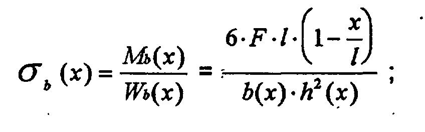
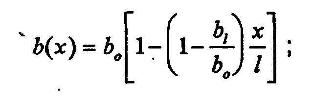
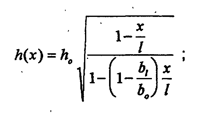
- the arms 22, 23 on both sides of the - Seen in the vertical direction - the thickest section of the cross central area 24 in their arm sections 221, 222, 231, 232 each essentially one rectangular cross-section (see the schematic area 37 in Fig. 4) with over the Length (arrow I in Fig. 4) seen different, to the respective bearing eye 223, 224, 233, 234 decreasing in size and conduct while driving normal forces occurring (see arrows F in Fig. 4) to stabilize the roll Vehicle superstructures in the central cross region 24.
Landscapes
- Engineering & Computer Science (AREA)
- Mechanical Engineering (AREA)
- Vehicle Body Suspensions (AREA)
Description
- Fig. 1
- eine Draufsicht auf das Fahrgestell eines Schwerlastkraftwagen im Bereich einer Hinterachse mit dem erfindungsgemäßen 4-Punkt-Stabilisatorlenker,
- Fig. 2
- eine Seitenansicht des hier vergrößert und allein dargestellten 4-Punkt-Stabilisatorlenkers aus Fig. 1,
- Fig. 3
- in Draufsicht den 4-Punkt-Stabilisatorlenker aus Fig. 1 vergrößert in Alleindarstellung, und
- Fig. 4
- ein mathematisch-physikalisches Ersatzbild für den erfindungsgemäßen 4-Punkt-Stabilisatorlenker.



Claims (6)
- Aufhängung einer Starrachse in einem Fahrzeug, insbesondere Nutzfahrzeug wie Lastkraftwagen oder Omnibus, mit je Fahrzeugseite einem Längslenker (17, 18), der in einer bestimmten Höhenlage einerseits am Starrachskörper (5), andererseits am Fahrzeugrahmen (1, 2, 3) angelenkt ist, und mit einem einstückigen 4-Punkt-Stabilisatorlenker(21), der auf drei Funktionen, nämlich Längskraftaufnahme, Seitenkraftaufnahme sowie Wankstabilisierung ausgelegt ist und aus zwei gekreuzten, in einer Ebene angeordneten Armen (22, 23) mit an jedem Ende einem Lagerauge und darin eingebautem Gelenk besteht, mit denen er einenendes am Starrachskörper in einer von den Anlenkstellen der Längslenker verschiedenen Höhenlage und andernendes an rahmenfesten Stellen angelenkt ist, dadurch gekennzeichnet, dass der 4-Punkt-Stabilisatorlenker (21) durch ein einstückiges Gesenkschmiedeteil gebildet ist, dessen gekreuzte Arme (22, 23)in einem Kreuzzentralbereich (24) ineinander übergehen,weitgehend nach Art von Parabelfedern entsprechend einem Biegeträger gleicher Festigkeit bzw. gleicher Randspannung ausgelegt sind,beiderseits des den dicksten Teil darstellenden Kreuzzentralbereiches (24) in den betreffenden Armabschnitten (221, 222 bzw. 231, 232) einen im wesentlichen rechteckigen Querschnitt mit über die Länge gesehen unterschiedlicher, zum jeweils außenendigen Lagerauge (223, 224 bzw. 233, 234) hin abnehmender Größe aufweisen, undauftretende Normalkräfte zur Wankstabilisierung in den Kreuzzentralbereich (24) einleiten.
- Aufhängung nach Anspruch 1, dadurch gekennzeichnet, daß die beiden sich beiderseits des Kreuzzentralbereiches (24) anschließenden Abschnitte (221, 222 bzw. 231, 232) eines jeden Armes (22, 23) des 4-Punkt-Stabilisatorlenkers (21) in Arm-Längsrichtung zumindest annähernd fluchtend zueinander verlaufen.
- Aufhängung nach Anspruch 1, dadurch gekennzeichnet, daß der Kreuzzentralbereich (24) des 4-Punkt-Stabilisatorlenkers (21) etwa in der Mitte der Längserstreckung von dessen beiden Armen (22, 23) angeordnet ist.
- Aufhängung nach Anspruch 1, dadurch gekennzeichnet, daß die Armabschnitte (221, 222 bzw. 231, 232) der beiden Arme (22, 23) des 4-Punkt-Stabilisatorlenkers (21) mit ihren seitlichen Außenflächen über am Außenbereich des Kreuzzentralbereiches (24) gegebene Hohlkehlen (33, 34, 35, 36) ineinander übergehen.
- Aufhängung nach Anspruch 1, dadurch gekennzeichnet, daß der Anschluß des 4-Punkt-Stabilisatorlenkers (21) an den Rahmen (1, 2, 3) und die Starrachse (4) über vier Pratzengelenke (25, 26, 27, 28) erfolgt, von denen jedes in eines der vier Lageraugen (223, 224 bzw. 223, 234) eingebaut ist, wobei die Achsen der beiden achsseitigen Pratzengelenke (27, 28) in den Lageraugen (224, 234) zueinander fluchtend in einer zur Längsmittelachse der Starrachse (4) parallelen Linie liegen, dagegen die Achsen der beiden rahmenseitigen Pratzengelenke (25, 26) im jeweils aufnehmenden Lagerauge (223, 233) - bezogen auf die durch das Zentrum des Kreuzzentralbereiches (24) gehende Fahrzeuglängsmittelhochebene - spiegelsymmetrisch entweder senkrecht oder unter leichtem spitzen Winkel zur Längsmittelachse des jeweiligen Armes (22, 23) bzw. rahmenseitigen Armabschnittes (221, 231) stehen.
- Aufhängung nach Anspruch 1, dadurch gekennzeichnet, daß die Fahrzeuglängsmittelhochebene durch das Zentrum des Kreuzzentralbereiches (24) des 4-Punkt-Stabilisatorlenkers (21) geht und dessen beiderseits der Fahrzeuglängsmittelhochebene gegebene Hälften spiegelsymmetrisch zu letzterer ausgebildet sind.
Applications Claiming Priority (2)
| Application Number | Priority Date | Filing Date | Title |
|---|---|---|---|
| DE19815776 | 1998-04-08 | ||
| DE19815776A DE19815776A1 (de) | 1998-04-08 | 1998-04-08 | Aufhängung einer Starrachse in einem Fahrzeug, insbesondere Nutzfahrzeug |
Publications (3)
| Publication Number | Publication Date |
|---|---|
| EP0949093A2 EP0949093A2 (de) | 1999-10-13 |
| EP0949093A3 EP0949093A3 (de) | 2001-10-31 |
| EP0949093B1 true EP0949093B1 (de) | 2002-09-25 |
Family
ID=7864012
Family Applications (1)
| Application Number | Title | Priority Date | Filing Date |
|---|---|---|---|
| EP99104065A Expired - Lifetime EP0949093B1 (de) | 1998-04-08 | 1999-03-17 | Aufhängung einer Starrachse in einem Fahrzeug, insbesondere Nutzfahrzeug |
Country Status (2)
| Country | Link |
|---|---|
| EP (1) | EP0949093B1 (de) |
| DE (2) | DE19815776A1 (de) |
Families Citing this family (9)
| Publication number | Priority date | Publication date | Assignee | Title |
|---|---|---|---|---|
| DE19957628B4 (de) * | 1999-11-30 | 2008-06-26 | ZF Lemförder GmbH | Achsaufhängung für Starrachsen von Fahrzeugen |
| US6527286B2 (en) | 2000-12-06 | 2003-03-04 | The Boler Company | Vehicle suspension assembly |
| DE10106350A1 (de) * | 2001-02-09 | 2002-08-14 | Zahnradfabrik Friedrichshafen | Achsaufhängung für Starrachsen von Nutzfahrzeugen |
| DE10206809A1 (de) * | 2002-02-19 | 2003-09-18 | Man Nutzfahrzeuge Ag | Vierpunktlenker zur Anbindung einer Starrachse an den Rahmen eines Nutzfahrzeuges |
| DE102004014610B4 (de) * | 2004-03-23 | 2009-06-18 | Zf Friedrichshafen Ag | Vierpunktlenker |
| RU2345906C1 (ru) * | 2007-05-07 | 2009-02-10 | Расул Салихович Каримов | Балансирная подвеска автосамосвала |
| DE102008057543A1 (de) * | 2008-11-08 | 2010-05-12 | Daimler Ag | Antriebsstranganordnung |
| DE102010009519A1 (de) | 2010-02-26 | 2011-09-01 | Man Truck & Bus Ag | Nutzfahrzeug mit Trägerrahmen und Doppelachskonstruktion |
| DE102012013694A1 (de) * | 2012-07-10 | 2014-01-16 | Man Truck & Bus Ag | Vierpunktlenker zur Anbindung einer Starrachse an den Rahmen eines Nutzfahrzeugs |
Family Cites Families (3)
| Publication number | Priority date | Publication date | Assignee | Title |
|---|---|---|---|---|
| CA2084940C (en) * | 1991-12-10 | 1998-12-08 | John J. Vrana | Reinforced hollow upper control arm for vehicle suspension system |
| DE29506571U1 (de) * | 1995-04-18 | 1995-06-08 | Steyr-Daimler-Puch Ag, Wien | Verbundlenkerachse für Kraftfahrzeuge |
| DE19521874A1 (de) * | 1995-06-16 | 1996-12-19 | Lemfoerder Metallwaren Ag | Achsaufhängung für Starrachsen in Fahrzeugen |
-
1998
- 1998-04-08 DE DE19815776A patent/DE19815776A1/de not_active Withdrawn
-
1999
- 1999-03-17 DE DE59902814T patent/DE59902814D1/de not_active Expired - Lifetime
- 1999-03-17 EP EP99104065A patent/EP0949093B1/de not_active Expired - Lifetime
Also Published As
| Publication number | Publication date |
|---|---|
| EP0949093A3 (de) | 2001-10-31 |
| DE19815776A1 (de) | 1999-10-14 |
| EP0949093A2 (de) | 1999-10-13 |
| DE59902814D1 (de) | 2002-10-31 |
Similar Documents
| Publication | Publication Date | Title |
|---|---|---|
| DE102014205632A1 (de) | Einzelradaufhängung sowie Hinterachse mit Einzelradaufhängungen für ein Fahrzeug und entsprechend ausgestattetes Fahrzeug | |
| EP1057665A1 (de) | Achsaufhängung für Starrachsen in Fahrzeugen | |
| EP1080953A1 (de) | Radaufhängung für Kraftfahrzeuge mit einer radführenden Blattfeder | |
| EP1900554A1 (de) | Einzelradaufhängung vom Doppelquerlenker-Typ | |
| DE19605283B4 (de) | Längslenkeraufhängung für Fahrzeuge | |
| DE19515565B4 (de) | Hinterradaufhängung für Kraftfahrzeuge | |
| EP3922489B1 (de) | X-federeinrichtung für eine kraftfahrzeug-radaufhängung | |
| EP1302342B1 (de) | Federungssystem für eine pendelnd gelagerte Achse | |
| EP3257691B1 (de) | Nutzfahrzeugfahrwerks-tragwerk und nutzfahrzeugfahrwerk | |
| WO2007087797A1 (de) | Radaufhängung für ein kraftfahrzeug | |
| EP0352541B1 (de) | Federnde Achsaufhängung für Kraftfahrzeuge, insbesondere Nutzfahrzeuge | |
| EP1826100B1 (de) | Querträgerverbund für ein luftgefedertes Nutzfahrzeug | |
| EP1541393B1 (de) | Torsionsachse | |
| DE102014205635A1 (de) | Einzelradaufhängung sowie Hinterachse mit Einzelradaufhängungen für ein Fahrzeug und entsprechend ausgestattetes Fahrzeug | |
| DE202014101432U1 (de) | Einzelradaufhängung sowie Hinterachse mit Einzelradaufhängungen für ein Fahrzeug und entsprechend ausgestattetes Fahrzeug | |
| EP0949093A2 (de) | Aufhängung einer Starrachse in einem Fahrzeug, insbesondere Nutzfahrzeug | |
| EP1057716B1 (de) | Achskonstruktion für Nutzfahrzeuge, Nutzfahrzeuganhänger und -auflieger | |
| EP0502310A1 (de) | Luftgefederte, lenkbare Räder tragende Achse eines Kraftfahrzeuges, insbesondere Niederflurbus | |
| DE3133312A1 (de) | "aufbauseitiger lagerbock eines kraftfahrzeuges " | |
| EP1777085A2 (de) | Achsaufhängung für eine längslenkergeführte Fahrzeugachse | |
| DE10016887C5 (de) | Einzelradaufhängung | |
| EP4335668A1 (de) | Achskonstruktion für ein nutzfahrzeug-fahrwerk mit einer als gussteil ausgeführten achsbrücke | |
| DE3039051A1 (de) | Starrachse, insbesondere angetriebene hinterachse fuer fahrzeuge | |
| DE102014200420B4 (de) | Einzelradaufhängung sowie Hinterachsmodul mit Einzelradaufhängungen für ein Fahrzeug und entsprechend ausgestattetes Fahrzeug | |
| DE102017206032B4 (de) | Verbundlenkerachse |
Legal Events
| Date | Code | Title | Description |
|---|---|---|---|
| PUAI | Public reference made under article 153(3) epc to a published international application that has entered the european phase |
Free format text: ORIGINAL CODE: 0009012 |
|
| AK | Designated contracting states |
Kind code of ref document: A2 Designated state(s): AT BE CH CY DE DK ES FI FR GB GR IE IT LI LU MC NL PT SE Kind code of ref document: A2 Designated state(s): DE FR IT NL SE |
|
| AX | Request for extension of the european patent |
Free format text: AL;LT;LV;MK;RO;SI |
|
| PUAL | Search report despatched |
Free format text: ORIGINAL CODE: 0009013 |
|
| AK | Designated contracting states |
Kind code of ref document: A3 Designated state(s): AT BE CH CY DE DK ES FI FR GB GR IE IT LI LU MC NL PT SE |
|
| AX | Request for extension of the european patent |
Free format text: AL;LT;LV;MK;RO;SI |
|
| 17P | Request for examination filed |
Effective date: 20011004 |
|
| 17Q | First examination report despatched |
Effective date: 20020116 |
|
| GRAG | Despatch of communication of intention to grant |
Free format text: ORIGINAL CODE: EPIDOS AGRA |
|
| GRAG | Despatch of communication of intention to grant |
Free format text: ORIGINAL CODE: EPIDOS AGRA |
|
| GRAH | Despatch of communication of intention to grant a patent |
Free format text: ORIGINAL CODE: EPIDOS IGRA |
|
| GRAH | Despatch of communication of intention to grant a patent |
Free format text: ORIGINAL CODE: EPIDOS IGRA |
|
| AKX | Designation fees paid |
Free format text: DE FR IT NL SE |
|
| GRAA | (expected) grant |
Free format text: ORIGINAL CODE: 0009210 |
|
| AK | Designated contracting states |
Kind code of ref document: B1 Designated state(s): DE FR IT NL SE |
|
| REF | Corresponds to: |
Ref document number: 59902814 Country of ref document: DE Date of ref document: 20021031 |
|
| ET | Fr: translation filed | ||
| PLBQ | Unpublished change to opponent data |
Free format text: ORIGINAL CODE: EPIDOS OPPO |
|
| PLBI | Opposition filed |
Free format text: ORIGINAL CODE: 0009260 |
|
| PLAX | Notice of opposition and request to file observation + time limit sent |
Free format text: ORIGINAL CODE: EPIDOSNOBS2 |
|
| 26 | Opposition filed |
Opponent name: ZF LEMFOERDER METALLWAREN AG Effective date: 20030624 |
|
| NLR1 | Nl: opposition has been filed with the epo |
Opponent name: ZF LEMFOERDER METALLWAREN AG |
|
| PLBB | Reply of patent proprietor to notice(s) of opposition received |
Free format text: ORIGINAL CODE: EPIDOSNOBS3 |
|
| PLCK | Communication despatched that opposition was rejected |
Free format text: ORIGINAL CODE: EPIDOSNREJ1 |
|
| APAY | Date of receipt of notice of appeal deleted |
Free format text: ORIGINAL CODE: EPIDOSDNOA2O |
|
| APBP | Date of receipt of notice of appeal recorded |
Free format text: ORIGINAL CODE: EPIDOSNNOA2O |
|
| APBP | Date of receipt of notice of appeal recorded |
Free format text: ORIGINAL CODE: EPIDOSNNOA2O |
|
| APAH | Appeal reference modified |
Free format text: ORIGINAL CODE: EPIDOSCREFNO |
|
| APBQ | Date of receipt of statement of grounds of appeal recorded |
Free format text: ORIGINAL CODE: EPIDOSNNOA3O |
|
| PLAB | Opposition data, opponent's data or that of the opponent's representative modified |
Free format text: ORIGINAL CODE: 0009299OPPO |
|
| R26 | Opposition filed (corrected) |
Opponent name: ZF LEMFOERDER GMBH Effective date: 20030624 |
|
| NLR1 | Nl: opposition has been filed with the epo |
Opponent name: ZF LEMFOERDER GMBH |
|
| APBU | Appeal procedure closed |
Free format text: ORIGINAL CODE: EPIDOSNNOA9O |
|
| PLBN | Opposition rejected |
Free format text: ORIGINAL CODE: 0009273 |
|
| STAA | Information on the status of an ep patent application or granted ep patent |
Free format text: STATUS: OPPOSITION REJECTED |
|
| 27O | Opposition rejected |
Effective date: 20081210 |
|
| NLR2 | Nl: decision of opposition |
Effective date: 20081210 |
|
| REG | Reference to a national code |
Ref country code: NL Ref legal event code: TD Effective date: 20110420 |
|
| REG | Reference to a national code |
Ref country code: FR Ref legal event code: CD |
|
| REG | Reference to a national code |
Ref country code: DE Ref legal event code: R081 Ref document number: 59902814 Country of ref document: DE Owner name: MAN TRUCK & BUS AG, DE Free format text: FORMER OWNER: MAN NUTZFAHRZEUGE AG, 80995 MUENCHEN, DE Effective date: 20110518 |
|
| REG | Reference to a national code |
Ref country code: FR Ref legal event code: PLFP Year of fee payment: 18 |
|
| PG25 | Lapsed in a contracting state [announced via postgrant information from national office to epo] |
Ref country code: IT Free format text: LAPSE BECAUSE OF NON-PAYMENT OF DUE FEES Effective date: 20160317 |
|
| REG | Reference to a national code |
Ref country code: FR Ref legal event code: PLFP Year of fee payment: 19 |
|
| PG25 | Lapsed in a contracting state [announced via postgrant information from national office to epo] |
Ref country code: IT Free format text: LAPSE BECAUSE OF NON-PAYMENT OF DUE FEES Effective date: 20160317 |
|
| PGRI | Patent reinstated in contracting state [announced from national office to epo] |
Ref country code: IT Effective date: 20170710 |
|
| REG | Reference to a national code |
Ref country code: FR Ref legal event code: PLFP Year of fee payment: 20 |
|
| PGFP | Annual fee paid to national office [announced via postgrant information from national office to epo] |
Ref country code: NL Payment date: 20180323 Year of fee payment: 20 |
|
| PGFP | Annual fee paid to national office [announced via postgrant information from national office to epo] |
Ref country code: SE Payment date: 20180327 Year of fee payment: 20 Ref country code: FR Payment date: 20180329 Year of fee payment: 20 |
|
| PGFP | Annual fee paid to national office [announced via postgrant information from national office to epo] |
Ref country code: DE Payment date: 20180530 Year of fee payment: 20 |
|
| PGFP | Annual fee paid to national office [announced via postgrant information from national office to epo] |
Ref country code: IT Payment date: 20180323 Year of fee payment: 20 |
|
| REG | Reference to a national code |
Ref country code: DE Ref legal event code: R071 Ref document number: 59902814 Country of ref document: DE |
|
| REG | Reference to a national code |
Ref country code: NL Ref legal event code: MK Effective date: 20190316 |