EP0949101B1 - Klappverdeck für Cabriofahrzeuge - Google Patents
Klappverdeck für Cabriofahrzeuge Download PDFInfo
- Publication number
- EP0949101B1 EP0949101B1 EP99101996A EP99101996A EP0949101B1 EP 0949101 B1 EP0949101 B1 EP 0949101B1 EP 99101996 A EP99101996 A EP 99101996A EP 99101996 A EP99101996 A EP 99101996A EP 0949101 B1 EP0949101 B1 EP 0949101B1
- Authority
- EP
- European Patent Office
- Prior art keywords
- main
- main column
- connecting rod
- folding top
- vehicle
- Prior art date
- Legal status (The legal status is an assumption and is not a legal conclusion. Google has not performed a legal analysis and makes no representation as to the accuracy of the status listed.)
- Expired - Lifetime
Links
- 238000006073 displacement reaction Methods 0.000 claims description 2
- 230000015572 biosynthetic process Effects 0.000 description 3
- 238000010276 construction Methods 0.000 description 3
- 238000010586 diagram Methods 0.000 description 2
- 239000004744 fabric Substances 0.000 description 2
- 238000004519 manufacturing process Methods 0.000 description 2
- 230000037237 body shape Effects 0.000 description 1
- 230000007797 corrosion Effects 0.000 description 1
- 238000005260 corrosion Methods 0.000 description 1
- 230000006735 deficit Effects 0.000 description 1
- 230000009189 diving Effects 0.000 description 1
- 230000002349 favourable effect Effects 0.000 description 1
Images


Classifications
-
- B—PERFORMING OPERATIONS; TRANSPORTING
- B60—VEHICLES IN GENERAL
- B60J—WINDOWS, WINDSCREENS, NON-FIXED ROOFS, DOORS, OR SIMILAR DEVICES FOR VEHICLES; REMOVABLE EXTERNAL PROTECTIVE COVERINGS SPECIALLY ADAPTED FOR VEHICLES
- B60J7/00—Non-fixed roofs; Roofs with movable panels, e.g. rotary sunroofs
- B60J7/08—Non-fixed roofs; Roofs with movable panels, e.g. rotary sunroofs of non-sliding type, i.e. movable or removable roofs or panels, e.g. let-down tops or roofs capable of being easily detached or of assuming a collapsed or inoperative position
- B60J7/12—Non-fixed roofs; Roofs with movable panels, e.g. rotary sunroofs of non-sliding type, i.e. movable or removable roofs or panels, e.g. let-down tops or roofs capable of being easily detached or of assuming a collapsed or inoperative position foldable; Tensioning mechanisms therefor, e.g. struts
- B60J7/1226—Soft tops for convertible vehicles
- B60J7/1265—Soft tops for convertible vehicles characterised by kinematic movements, e.g. using parallelogram linkages
Definitions
- the invention relates to a folding roof for convertible vehicles according to the preamble of claim 1.
- Such a folding roof is for example from the DE-C-3 724 532 or US-A-5 004 291 or the DE-C-34 05 920 known In the known hoods it is provided in each case that for the purpose of minimal impairment of the interior of the Vehicle in the folding roof located in its open position the main pillar of the convertible top is formed in several parts and essentially a main column section and a roof skin holding rail comprise, wherein the main pillar sections of the body contour of the Vehicle are arranged opposite to the inside and the roof skin holding rails hinged to the outside of the main column sections and such can be controlled that when opening the top from a to the contour the side wall of the vehicle body flush position in a closer to the assigned main column section moved convertible top folding position can be transferred are.
- DE-U-297 10 720 describes a convertible top for a convertible vehicle in which Linkage parts during a roof opening movement by means of. Spreading elements and guide wedges outwards from the head area of the Passengers are moved away.
- US-A-4,958,882 describes a convertible top for a convertible vehicle in which a free end of a column section by means of an inclined Axis of rotation during a convertible top closing movement in the direction of the Swiveling in the center of the vehicle, the swiveling in via a Link is positively controlled.
- a main bow and a steering lever are pivoted on a bearing plate fixed to the body.
- the invention is therefore based on the object of a folding top of the beginning mentioned type for convertible vehicles, especially those with essentially oval body cross-sectional shape and tapering towards the rear of the vehicle Body shape to further develop in that at least not larger Manufacturing effort on the one hand, the greatest possible shoulder freedom Rear passengers and on the other hand especially in the articulation area for the main pillars a narrow design of the necessary for the top compartment opening Free cut can be achieved in the vehicle body.
- a spatial four-bar link is provided at which the sum of the degrees of joint freedom is at least six, preferably seven, is.
- the main pillar connected at the bottom to the body by means of a rotating sliding joint is guaranteed that, as a result of the alignment of the upper articulation axes of main column and main link, the lower end of the main column during of folding the convertible top linkage to the center of the vehicle is shifted towards and thus a narrow in the vehicle transverse direction bundling of the side roof linkage takes up little space, which on the one hand allows the rear passengers sufficient shoulder room and secondly for immersing the convertible top in the convertible top compartment, especially in the area of the root of the main pillar only a relative one narrow clearance in the body is required.
- the invention further provided that the compulsory Relocation of the body-side linkage of the main pillar using a rigid auxiliary link is assigned, which is supported on the one hand on the body and on the other hand at a distance from their body-side linkage on the main pillar attacks.
- this first preferred form of implementation is particularly suitable for such folding tops, their main pillar and their main link with each other have unequal lengths.
- the main pillar and the main link are connected to the Vehicle body are connected, at least the body side End of the main column bearing axis between the two walls of the Console is arranged while the auxiliary link on the with respect to the vehicle longitudinal center inner wall of the bearings of the main column and Main link receiving console is arranged.
- the auxiliary link is expedient with respect to the median longitudinal plane of the vehicle arranged on the outside of the main column and console and both on the main column and also connected to the console by means of a ball joint.
- a two-bar linkage designed as a spatial parallelogram in which the sum of the degrees of joint freedom is only five.
- this second form of implementation is only suitable for folding tops whose main pillar and main link have absolutely identical lengths to one another.
- the articulations of the main pillar and main link on the one hand on the vehicle body and on the other hand on the rear Roof frame part are designed so that they as a spatial parallelogram trained four-bar linkage in which the sum of the degrees of joint freedom is only five.
- a folding top designed in this way is characterized in that that the main pillar and the main link are of equal lengths to each other have and about mutually parallel, skewed articulation axes on the rear roof frame part and around each other parallel to the longitudinal plane of the vehicle aligned axes articulated on the vehicle body are, with only the body-side articulation of the main column transverse to
- the longitudinal center plane of the vehicle can also be shifted to this form of realization provided that at least the main pillar on the body supporting sliding joint is accommodated in a double-walled console and the displacement of the lower end of the main pillar to the median longitudinal plane is enforced by an auxiliary link.
- the folding top for convertible vehicles shown includes the top linkage in the usual way a group of frame parts and one Group of handlebars, the group of frame parts being a front 1 and a rear roof frame part 2 a main pillar 3 and a fabric tensioning bracket 4 and the Group of handlebars a main link 5 and on the one hand the fabric tensioning bracket 4th assigned tie rods 6 and 7 and on the other hand the movement of the front Roof frame part 1 associated drive link 8 and 9.
- To the front Roof frame part 1 is a closed roof on the in the drawing in Individual front windshield frame, not shown, on front bow 10 connected.
- the front roof frame part 1 is transverse to Vehicle longitudinal center plane aligned axis 11 pivotable with the rear Roof frame part 2 connected, which in turn at the rear on the main pillar 3rd is articulated.
- the main link 5 is at its upper end by means of one about an axis aligned horizontally and transversely to the median longitudinal plane of the vehicle 12 with the drive link 8 in drive connection.
- On the rear roof part 2 is the main link 5 around a first pivot point of a spatial four-bar linkage forming skewed axis 13 articulated.
- Main column 3 at the top around a skewed and parallel to the articulation axis 13 of the Main link 5 aligned, a second hinge point of the spatial four-bar forming axis 14 connected to the free end of the rear roof frame part 2.
- the main link 5 is a third by means of one Articulation point of the spatial four-bar joint 15 to an in not shown with the vehicle body. connected console 16 connected.
- the main column 3 is at the bottom by means of a bearing eye 17 arranged horizontally and transversely to the median longitudinal plane of the vehicle Axis 18 can be pivoted and displaced transversely to the vehicle's longitudinal center axis supported, the sliding joint 17/18 the fourth hinge point of the spatial Quadrilateral forms.
- the axis 17 is between the two walls 19 and 20 of the console 16, while the main arm 5 supporting, the third joint point of the spatial four-bar ball joint 15 on the inner wall 20 of the vehicle longitudinal center Console 16 is arranged.
- the top linkage is the body-side link 17/18 of the main pillar 3 a rigid auxiliary link 21 is assigned, on the one hand by means of the console 16 is supported on the body and on the other hand at a distance from the latter Body-side linkage 17/18 attacks on the main pillar 3.
- the auxiliary handlebar 21 is with respect to the median longitudinal plane of the main pillar 3 and the console 16 arranged on the outside and on both the main column 3 and the console 16 connected by means of a ball joint 22.
Landscapes
- Engineering & Computer Science (AREA)
- Mechanical Engineering (AREA)
- Body Structure For Vehicles (AREA)
- Fittings On The Vehicle Exterior For Carrying Loads, And Devices For Holding Or Mounting Articles (AREA)
- Tents Or Canopies (AREA)
- Air Bags (AREA)
- Seal Device For Vehicle (AREA)
Description
Diese zweite Verwirklichungsform eignet sich im Einzelnen ausschließlich für solche Klappverdecke, deren Hauptsäule und deren Hauptlenker untereinander absolut gleiche Längen aufweisen.
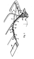
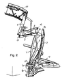
In der Zeichnung zeigt die
- Fig. 1
- eine Seitenansicht des Verdeckgestänges eines Klappverdeckes bei in der Schließlage befindlichem Verdeck;
- Fig. 2
- eine ausschnittweise schaubildliche Darstellung des Verdeckgestänges eines Klappverdeckes nach Figur 1 bei in einer Teilöffnungslage befindlichem Verdeck;
- Fig. 3
- eine Draufsicht auf das Verdeckgestänge eines Klappverdeckes nach Figur 1 bei in einer Teilöffnungslage befindlichem Verdeck;
- Figur 4
- eine ausschnittsweise schaubildliche Darstellung der Anbindung von Hauptsäule und Hauptlenker des Verdeckgestänges an die Fahrzeugkarosserie, im vergrößerten Maßstab.
Claims (10)
- Klappverdeck für Cabriofahrzeuge mit einem zum Öffnen des Verdeckes einklappbaren Verdeckgestänge, welches eine um eine quer zur Fahrzeuglängsmittelebene ausgerichtete Achse (18) schwenkbar an die Fahrzeugkarosserie angeschlossene Hauptsäule (3), einen um eine horizontale Achse (14) schwenkbar mit dieser -verbundenen. hinteren Dachrahmenteil (2) sowie einen einerseits an der Fahrzeugkarosserie und andererseits am hinteren Dachrahmenteil (2) angelenkten Hauptlenker (5) .umfaßt, wobei die Anlenkungen von Hauptsäule (3) und Hauptlenker (5) einerseits an der Fahrzeugkarosserie und andererseits am hinteren Dachrahmenteil (2) derart gestaltet sind, daß sie ein räumliches Viergelenk bilden,
dadurch gekennzeichnet, daß die karosserieseitige Anlenkung (17, 18) der Hauptsäule (3) auf einer horizontalen, quer zur Fahrzeuglängsmittelebene ausgerichteten Achse (18) verlagerbar angeordnet ist. - Klappverdeck nach Anspruch 1, dadurch gekennzeichnet, daß in Verbindung mit einer zueinander parallelen Anordnung und windschiefen Ausrichtung der Anlenkachsen von Hauptsäule und Hauptlenker am hinteren Dachrahmenteil die karosserieseitige Anlenkung des Hauptlenkers als Kugelgelenk, wobei die karosserieseitige Anlenkung der Hauptsäule auf eine horizontalen quer zur Fahrzeuglängsmittelebene ausgerichteten Achse verlagerbar angeordnet ist.
- Klappverdeck nach Anspruch 1 oder 2, dadurch gekennzeichnet, daß die karosserieseitige Anlenkung der Hauptsäule (3) als quer zur Fahrzeuglängsmittelebene verstellbares Schiebegelenk (17) ausgebildet ist.
- Klappverdeck nach einem der Ansprüche 1 bis 3, dadurch gekennzeichnet, daß die Hauptsäule (3) und der Hauptlenker (5) untereinander ungleiche Längen aufweisen.
- Klappverdeck nach einem der Ansprüche 1 bis 4, dadurch gekennzeichnet, daß die Hauptsäule (3) und der Hauptlenker (5) vermittels einer doppelwandigen Konsole (16) an die Fahrzeugkarosserie angeschlossen sind, wobei wenigstens die das karosserieseitige Ende der Hauptsäule (3) lagernde Achse (18) zwischen den beiden Wandungen der Konsole (16) angeordnet ist.
- Klappverdeck nach einem der Ansprüche 1 bis 5, dadurch gekennzeichnet, daß der zwangsweisen Verlagerung der karosserieseitigen Anlenkung der Hauptsäule (3) ein starrer Hilfslenker (21) zugeordnet ist, welcher einerseits an der Karosserie abgestützt ist und andererseits mit einem Abstand zu deren karosserieseitigen Anlenkung an der Hauptsäule (3) angreift.
- Klappverdeck nach Anspruch 6, dadurch gekennzeichnet, daß der Hilfslenker (21) an der bezüglich der Fahrzeuglängsmitte außenliegenden Wandung der die Lagerungen von Hauptsäule (3) und Hauptlenker (5) aufnehmenden Konsole (16) angeordnet ist.
- Klappverdeck nach Anspruch 6 oder 7, dadurch gekennzeichnet, daß der Hilfslenker (21) sowohl an die Hauptsäule (3) als auch an die Konsole (16) vermittels eines Kugelgelenkes (22) angeschlossen ist.
- Klappverdeck nach Anspruch 1, dadurch gekennzeichnet, daß das räumliche Viergelenk als räumliches Parallelogramm ausgebildet ist, bei dem die Summe der Gelenkfreiheitsgrade lediglich 5 beträgt.
- Klappverdeck nach Anspruch 9, dadurch gekennzeichnet, daß die Hauptsäule (3) und der Hauptlenker (5) untereinander gleiche Längen aufweisen und um zueinander parallele, windschief ausgerichtete Anlenkachsen (13, 14) am hinteren Dachrahmenteil (2) und um zueinander parallele, quer zur Fahrzeuglängsmittelebene ausgerichtete Achsen an der Fahrzeugkarosserie angelenkt sind, wobei lediglich die karosserieseitige Anlenkung (17, 18) der Hauptsäule (3) quer zur Fahrzeuglängsmittelebene verlagerbar ist.
Applications Claiming Priority (2)
| Application Number | Priority Date | Filing Date | Title |
|---|---|---|---|
| DE19815980 | 1998-04-09 | ||
| DE19815980A DE19815980A1 (de) | 1998-04-09 | 1998-04-09 | Klappverdeck für Cabriofahrzeuge |
Publications (3)
| Publication Number | Publication Date |
|---|---|
| EP0949101A2 EP0949101A2 (de) | 1999-10-13 |
| EP0949101A3 EP0949101A3 (de) | 1999-12-01 |
| EP0949101B1 true EP0949101B1 (de) | 2004-06-02 |
Family
ID=7864142
Family Applications (1)
| Application Number | Title | Priority Date | Filing Date |
|---|---|---|---|
| EP99101996A Expired - Lifetime EP0949101B1 (de) | 1998-04-09 | 1999-02-01 | Klappverdeck für Cabriofahrzeuge |
Country Status (3)
| Country | Link |
|---|---|
| EP (1) | EP0949101B1 (de) |
| AT (1) | ATE268276T1 (de) |
| DE (2) | DE19815980A1 (de) |
Families Citing this family (5)
| Publication number | Priority date | Publication date | Assignee | Title |
|---|---|---|---|---|
| DE19962995B4 (de) * | 1999-12-24 | 2008-06-12 | Wilhelm Karmann Gmbh | Cabriolet-Fahrzeug mit einem zumindest bereichsweise flexiblen Dach |
| DE10160240B4 (de) * | 2001-12-07 | 2005-04-07 | Webasto Ag | Faltverdeck für ein Kraftfahrzeug |
| DE10349819B4 (de) * | 2003-10-24 | 2005-09-01 | Wilhelm Karmann Gmbh | Cabriolet-Fahrzeug |
| DE102006009548A1 (de) * | 2006-02-28 | 2007-08-30 | Wilhelm Karmann Gmbh | Cabriolet-Fahrzeug mit einer Hauptsäule |
| DE102009005934A1 (de) * | 2009-01-23 | 2010-08-19 | Magna Car Top Systems Gmbh | Zusammenlegbares Dach für einen Personenkraftwagen |
Family Cites Families (5)
| Publication number | Priority date | Publication date | Assignee | Title |
|---|---|---|---|---|
| DE3405920C2 (de) | 1984-02-18 | 1985-12-12 | Daimler-Benz Ag, 7000 Stuttgart | Klappverdeck für Fahrzeuge, insbesondere für Personenkraftwagen |
| DE3428453A1 (de) | 1984-08-01 | 1986-02-13 | Siemens AG, 1000 Berlin und 8000 München | Sensoreinrichtung |
| DE3724532C1 (de) * | 1987-07-24 | 1988-11-10 | Daimler Benz Ag | Verdeckgestell eines Klappverdecks fuer Fahrzeuge |
| DE3825790A1 (de) * | 1988-07-29 | 1990-02-08 | Porsche Ag | Klappverdeck fuer fahrzeuge |
| DE29710720U1 (de) * | 1997-06-19 | 1998-04-02 | Wilhelm Karmann GmbH, 49084 Osnabrück | Verdeck für ein Cabriolet-Fahrzeug |
-
1998
- 1998-04-09 DE DE19815980A patent/DE19815980A1/de not_active Withdrawn
-
1999
- 1999-02-01 DE DE59909627T patent/DE59909627D1/de not_active Expired - Lifetime
- 1999-02-01 EP EP99101996A patent/EP0949101B1/de not_active Expired - Lifetime
- 1999-02-01 AT AT99101996T patent/ATE268276T1/de not_active IP Right Cessation
Also Published As
| Publication number | Publication date |
|---|---|
| EP0949101A2 (de) | 1999-10-13 |
| EP0949101A3 (de) | 1999-12-01 |
| ATE268276T1 (de) | 2004-06-15 |
| DE59909627D1 (de) | 2004-07-08 |
| DE19815980A1 (de) | 1999-10-21 |
Similar Documents
| Publication | Publication Date | Title |
|---|---|---|
| DE10116709C2 (de) | Klappverdeck mit Heckscheibensteuerung | |
| EP1127725B1 (de) | Faltverdeck für ein Kraftfahrzeug | |
| DE4316485A1 (de) | Klappverdeck für Kraftfahrzeuge | |
| EP0922597A1 (de) | Kraftfahrzeug mit einer versenkbaren Dachkonstruktion | |
| EP0760301A1 (de) | Faltverdeck für ein Cabriolet-Fahrzeug | |
| DE10107078B4 (de) | Umwandelbares Fahrzeugdach | |
| DE10102643A1 (de) | Faltverdeck für ein Kraftfahzeug | |
| DE19647128A1 (de) | Schwenklagerung für eine aufklappbare Fahrzeugtür | |
| DE102005033599A1 (de) | Verstellvorrichtung eines Verdeckkastendeckels eines Cabriolets | |
| EP0879722B1 (de) | Faltverdeck für einen Personenkraftwagen | |
| EP1254800B1 (de) | Dachanordnung für ein Fahrzeug | |
| EP0949101A2 (de) | Klappverdeck für Cabriofahrzeuge | |
| DE19646035C2 (de) | Faltverdeck für ein Kraftfahrzeug, insbesondere Geländewagen | |
| DE102007004180B4 (de) | Verstellbares Fahrzeugdach | |
| EP1982858B1 (de) | Umwandelbares Dach fuer einen Personenkraftwagen | |
| DE10140433A1 (de) | Verdeck für ein Kraftfahrzeug | |
| DE19741264A1 (de) | Personenkraftwagen mit bewegbarem starren Dachteil und Heckscheibenteil | |
| DE10117767A1 (de) | Heckseitige Abdeckung für ein Cabriolet | |
| EP0952022B1 (de) | Klappverdeck für Cabriofahrzeuge | |
| DE19962995A1 (de) | Cabriolet-Fahrzeug mit einem zumindest bereichsweise flexiblen Dach | |
| EP1284211A2 (de) | Kraftfahrzeug mit einem beweglichen Dach | |
| DE102018211256B4 (de) | Türantrieb für eine Kraftwagentür sowie Halteanordnung | |
| DE9307481U1 (de) | Klappverdeck für Kraftfahrzeuge | |
| DE29806543U1 (de) | Klappverdeck für Cabriofahrzeuge | |
| DE19610969C2 (de) | Klappverdeck für Personenkraftwagen |
Legal Events
| Date | Code | Title | Description |
|---|---|---|---|
| PUAI | Public reference made under article 153(3) epc to a published international application that has entered the european phase |
Free format text: ORIGINAL CODE: 0009012 |
|
| 17P | Request for examination filed |
Effective date: 19990201 |
|
| AK | Designated contracting states |
Kind code of ref document: A2 Designated state(s): AT DE FR GB IT SE |
|
| AX | Request for extension of the european patent |
Free format text: AL;LT;LV;MK;RO;SI |
|
| PUAL | Search report despatched |
Free format text: ORIGINAL CODE: 0009013 |
|
| AK | Designated contracting states |
Kind code of ref document: A3 Designated state(s): AT BE CH CY DE DK ES FI FR GB GR IE IT LI LU MC NL PT SE |
|
| AX | Request for extension of the european patent |
Free format text: AL;LT;LV;MK;RO;SI |
|
| AKX | Designation fees paid |
Free format text: AT DE FR GB IT SE |
|
| RAP1 | Party data changed (applicant data changed or rights of an application transferred) |
Owner name: EDSCHA CABRIO-VERDECKSYSTEME GMBH |
|
| RAP1 | Party data changed (applicant data changed or rights of an application transferred) |
Owner name: EDSCHA CABRIO-DACHSYSTEME GMBH |
|
| 17Q | First examination report despatched |
Effective date: 20011029 |
|
| GRAP | Despatch of communication of intention to grant a patent |
Free format text: ORIGINAL CODE: EPIDOSNIGR1 |
|
| GRAS | Grant fee paid |
Free format text: ORIGINAL CODE: EPIDOSNIGR3 |
|
| GRAA | (expected) grant |
Free format text: ORIGINAL CODE: 0009210 |
|
| AK | Designated contracting states |
Kind code of ref document: B1 Designated state(s): AT DE FR GB IT SE |
|
| PG25 | Lapsed in a contracting state [announced via postgrant information from national office to epo] |
Ref country code: IT Free format text: LAPSE BECAUSE OF FAILURE TO SUBMIT A TRANSLATION OF THE DESCRIPTION OR TO PAY THE FEE WITHIN THE PRESCRIBED TIME-LIMIT;WARNING: LAPSES OF ITALIAN PATENTS WITH EFFECTIVE DATE BEFORE 2007 MAY HAVE OCCURRED AT ANY TIME BEFORE 2007. THE CORRECT EFFECTIVE DATE MAY BE DIFFERENT FROM THE ONE RECORDED. Effective date: 20040602 Ref country code: GB Free format text: LAPSE BECAUSE OF FAILURE TO SUBMIT A TRANSLATION OF THE DESCRIPTION OR TO PAY THE FEE WITHIN THE PRESCRIBED TIME-LIMIT Effective date: 20040602 Ref country code: FR Free format text: LAPSE BECAUSE OF FAILURE TO SUBMIT A TRANSLATION OF THE DESCRIPTION OR TO PAY THE FEE WITHIN THE PRESCRIBED TIME-LIMIT Effective date: 20040602 |
|
| REG | Reference to a national code |
Ref country code: GB Ref legal event code: FG4D Free format text: NOT ENGLISH |
|
| REF | Corresponds to: |
Ref document number: 59909627 Country of ref document: DE Date of ref document: 20040708 Kind code of ref document: P |
|
| PG25 | Lapsed in a contracting state [announced via postgrant information from national office to epo] |
Ref country code: SE Free format text: LAPSE BECAUSE OF FAILURE TO SUBMIT A TRANSLATION OF THE DESCRIPTION OR TO PAY THE FEE WITHIN THE PRESCRIBED TIME-LIMIT Effective date: 20040902 |
|
| GBV | Gb: ep patent (uk) treated as always having been void in accordance with gb section 77(7)/1977 [no translation filed] |
Effective date: 20040602 |
|
| PG25 | Lapsed in a contracting state [announced via postgrant information from national office to epo] |
Ref country code: AT Free format text: LAPSE BECAUSE OF NON-PAYMENT OF DUE FEES Effective date: 20050201 |
|
| PLBE | No opposition filed within time limit |
Free format text: ORIGINAL CODE: 0009261 |
|
| STAA | Information on the status of an ep patent application or granted ep patent |
Free format text: STATUS: NO OPPOSITION FILED WITHIN TIME LIMIT |
|
| 26N | No opposition filed |
Effective date: 20050303 |
|
| EN | Fr: translation not filed | ||
| PGFP | Annual fee paid to national office [announced via postgrant information from national office to epo] |
Ref country code: DE Payment date: 20180221 Year of fee payment: 20 |
|
| REG | Reference to a national code |
Ref country code: DE Ref legal event code: R071 Ref document number: 59909627 Country of ref document: DE |