EP0949112B1 - Modulares Befestigungssystem im Innenraum eines Kraftfahrzeuges - Google Patents
Modulares Befestigungssystem im Innenraum eines Kraftfahrzeuges Download PDFInfo
- Publication number
- EP0949112B1 EP0949112B1 EP19990400817 EP99400817A EP0949112B1 EP 0949112 B1 EP0949112 B1 EP 0949112B1 EP 19990400817 EP19990400817 EP 19990400817 EP 99400817 A EP99400817 A EP 99400817A EP 0949112 B1 EP0949112 B1 EP 0949112B1
- Authority
- EP
- European Patent Office
- Prior art keywords
- slider
- slide rail
- slide
- longitudinal
- base
- Prior art date
- Legal status (The legal status is an assumption and is not a legal conclusion. Google has not performed a legal analysis and makes no representation as to the accuracy of the status listed.)
- Expired - Lifetime
Links
- 238000004873 anchoring Methods 0.000 title 1
- 210000001520 comb Anatomy 0.000 claims description 19
- 230000000295 complement effect Effects 0.000 claims description 6
- 230000037431 insertion Effects 0.000 claims 1
- 238000003780 insertion Methods 0.000 claims 1
- 210000000056 organ Anatomy 0.000 description 26
- 238000000429 assembly Methods 0.000 description 7
- 238000006073 displacement reaction Methods 0.000 description 6
- 238000000605 extraction Methods 0.000 description 4
- 239000000463 material Substances 0.000 description 4
- 244000245420 ail Species 0.000 description 3
- 230000008901 benefit Effects 0.000 description 2
- 238000004519 manufacturing process Methods 0.000 description 2
- 230000000284 resting effect Effects 0.000 description 2
- 230000035939 shock Effects 0.000 description 2
- 229910000831 Steel Inorganic materials 0.000 description 1
- 230000001133 acceleration Effects 0.000 description 1
- 230000006835 compression Effects 0.000 description 1
- 238000007906 compression Methods 0.000 description 1
- 238000005242 forging Methods 0.000 description 1
- 238000003754 machining Methods 0.000 description 1
- 239000002184 metal Substances 0.000 description 1
- 238000000034 method Methods 0.000 description 1
- 239000003607 modifier Substances 0.000 description 1
- 238000000465 moulding Methods 0.000 description 1
- 238000004080 punching Methods 0.000 description 1
- 238000010008 shearing Methods 0.000 description 1
- 239000010959 steel Substances 0.000 description 1
- 210000001364 upper extremity Anatomy 0.000 description 1
- XLYOFNOQVPJJNP-UHFFFAOYSA-N water Substances O XLYOFNOQVPJJNP-UHFFFAOYSA-N 0.000 description 1
Images


Classifications
-
- B—PERFORMING OPERATIONS; TRANSPORTING
- B60—VEHICLES IN GENERAL
- B60N—SEATS SPECIALLY ADAPTED FOR VEHICLES; VEHICLE PASSENGER ACCOMMODATION NOT OTHERWISE PROVIDED FOR
- B60N2/00—Seats specially adapted for vehicles; Arrangement or mounting of seats in vehicles
- B60N2/02—Seats specially adapted for vehicles; Arrangement or mounting of seats in vehicles the seat or part thereof being movable, e.g. adjustable
- B60N2/04—Seats specially adapted for vehicles; Arrangement or mounting of seats in vehicles the seat or part thereof being movable, e.g. adjustable the whole seat being movable
- B60N2/06—Seats specially adapted for vehicles; Arrangement or mounting of seats in vehicles the seat or part thereof being movable, e.g. adjustable the whole seat being movable slidable
- B60N2/08—Seats specially adapted for vehicles; Arrangement or mounting of seats in vehicles the seat or part thereof being movable, e.g. adjustable the whole seat being movable slidable characterised by the locking device
- B60N2/0812—Location of the latch
- B60N2/0818—Location of the latch inside the rail
-
- B—PERFORMING OPERATIONS; TRANSPORTING
- B60—VEHICLES IN GENERAL
- B60N—SEATS SPECIALLY ADAPTED FOR VEHICLES; VEHICLE PASSENGER ACCOMMODATION NOT OTHERWISE PROVIDED FOR
- B60N2/00—Seats specially adapted for vehicles; Arrangement or mounting of seats in vehicles
- B60N2/005—Arrangement or mounting of seats in vehicles, e.g. dismountable auxiliary seats
- B60N2/015—Attaching seats directly to vehicle chassis
- B60N2/01508—Attaching seats directly to vehicle chassis using quick release attachments
- B60N2/01516—Attaching seats directly to vehicle chassis using quick release attachments with locking mechanisms
- B60N2/01525—Attaching seats directly to vehicle chassis using quick release attachments with locking mechanisms with locking elements expanding inside or under the vehicle floor or rail
- B60N2/01541—Attaching seats directly to vehicle chassis using quick release attachments with locking mechanisms with locking elements expanding inside or under the vehicle floor or rail using moving hooks
-
- B—PERFORMING OPERATIONS; TRANSPORTING
- B60—VEHICLES IN GENERAL
- B60N—SEATS SPECIALLY ADAPTED FOR VEHICLES; VEHICLE PASSENGER ACCOMMODATION NOT OTHERWISE PROVIDED FOR
- B60N2/00—Seats specially adapted for vehicles; Arrangement or mounting of seats in vehicles
- B60N2/02—Seats specially adapted for vehicles; Arrangement or mounting of seats in vehicles the seat or part thereof being movable, e.g. adjustable
- B60N2/04—Seats specially adapted for vehicles; Arrangement or mounting of seats in vehicles the seat or part thereof being movable, e.g. adjustable the whole seat being movable
- B60N2/06—Seats specially adapted for vehicles; Arrangement or mounting of seats in vehicles the seat or part thereof being movable, e.g. adjustable the whole seat being movable slidable
- B60N2/07—Slide construction
- B60N2/0702—Slide construction characterised by its cross-section
- B60N2/072—Complex cross-section, e.g. obtained by extrusion
-
- B—PERFORMING OPERATIONS; TRANSPORTING
- B60—VEHICLES IN GENERAL
- B60N—SEATS SPECIALLY ADAPTED FOR VEHICLES; VEHICLE PASSENGER ACCOMMODATION NOT OTHERWISE PROVIDED FOR
- B60N2/00—Seats specially adapted for vehicles; Arrangement or mounting of seats in vehicles
- B60N2/02—Seats specially adapted for vehicles; Arrangement or mounting of seats in vehicles the seat or part thereof being movable, e.g. adjustable
- B60N2/04—Seats specially adapted for vehicles; Arrangement or mounting of seats in vehicles the seat or part thereof being movable, e.g. adjustable the whole seat being movable
- B60N2/06—Seats specially adapted for vehicles; Arrangement or mounting of seats in vehicles the seat or part thereof being movable, e.g. adjustable the whole seat being movable slidable
- B60N2/08—Seats specially adapted for vehicles; Arrangement or mounting of seats in vehicles the seat or part thereof being movable, e.g. adjustable the whole seat being movable slidable characterised by the locking device
- B60N2/0831—Movement of the latch
- B60N2/0837—Movement of the latch pivoting
- B60N2/0843—Movement of the latch pivoting about a longitudinal axis
Definitions
- the invention provides a system for adjusting the longitudinal position, and locking in the adjusted position of a sub-assembly on the horizontal floor of the passenger compartment of a motor vehicle.
- each end of the sub-base has two bolts of substantially longitudinal orientation, articulated around a pivot of longitudinal axis movable vertically, to selectively move upper extremities and lower bolts so that they selectively cooperate with respectively upper and lower zones of the associated slide, so as to ensure functions of longitudinal guiding, locking or unlocking by jamming, and vertical locking or extraction by jamming or loosening.
- the pivot of articulation of the bolts is animated by a movement of vertical translation which it transforms into a movement of rotation of the bolts along the axis of the slide.
- This movement of vertical translation is obtained by vertical displacement of the pivot, consisting of a ball forming a nut, along the thread a screw linked to a frame of said device, and whose screwing or unscrewing selectively causes the spacing or approximation of the bolts, and, consequently immobilization of the base relative to the slide.
- the sub-assemblies being likely to constitute loads having large vertical dimensions, their fastening system must be designed to withstand non-uniform tearing of the anchor points. If, for any reason, a subset with more of an anchor point sees one of its anchor points torn off, it occurs the appearance of a couple on the other points anchor and the whole load fixing is weakened. In the event of an impact, the load forming the lever arm, the longitudinal accelerations of the load are likely to exert a shearing force on the anchor points of sub-assemblies, which may cause rupture of the anchor points of the sub-assemblies in case the means of locking the anchor points are insufficient.
- this system does not provide a fixing system of any subset by means of rings and straps.
- this solution is not acceptable in the case of a non-utility vehicle, and in particular a vehicle versatile such as a people carrier, in which the passenger compartment is led to receive seats, and therefore cannot include protruding rings permanently installed to meet aesthetic and safety imperatives, passengers who may be injured by the rings.
- the invention proposes a new conception of a previously mentioned type adjustment system which overcomes the aforementioned drawbacks.
- the invention proposes a system of the type previously described, characterized in that the sub-assembly has a ring and that the first slide is ordered in its vertical displacement by manual actions vertical on the lashing ring which is integral with the first slide, and in that the second slide is controlled in its vertical movements by manual actions vertical on a gripping ring secured to the second slide.
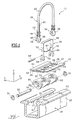
- the system 10 comprises a base 12 produced in the form of a horizontal plate which extends parallel to a floor (not shown) of the vehicle, and which can optionally be associated with an element interior design of the vehicle such as a seat, shelf or any interior design element (not shown).
- the base 12 is intended to be received, as seen also in FIG. 2, in a slide 16 which is fixed to the vehicle floor.
- the slide 16 is made from a profile, for example a drawn bar or Pressed.
- the base 12 has two horizontal wings 24, symmetrical with respect to the median longitudinal plane P of the slide 16, which extend transversely over the entire length of the base 12, and which have on their faces lower 26 of the pads 28, made of low material coefficient of friction, intended, as can also be seen in the Figure 2, to allow the support of the base 12 on two wings upper 30 of the slide 16, which extend horizontally and transversely outwards, and in part inwards, from the end edges upper side faces 32 of the slide 16.
- the pads of low material coefficient of friction 28 are carried by the base 12, which reduces their length to the longitudinal dimension of the base 12, thereby significantly lowering the manufacturing costs, as opposed to a design where the pads 28 would extend longitudinally over the entire length upper wings 30 of the slide 16.
- a central part longitudinal 18 of base 12 is pierced with oblong holes 20, vertical direction, and which extend transversely from side and on the other side of the median plane P of the device 10, to receive in vertical sliding a first slide 36.
- the slide 36 has, in an upper part, a ring lashing 22, inverted U-shaped fitting in the plane median P, and which is advantageously produced from a curved bar in an appropriate shape.
- the slide In a part lower extending the branches of the U of the ring 22, the slide has two coaxial bores 34 and longitudinal.
- the bores 34 are carried by shapes in hook 38 made of material with the arched bar of the ring lashing 22.
- the slide 36 can then advantageously be made in one piece, for example by deformation plastic of a steel wire.
- the slide 36 is guided in its movements vertical by contact of intermediate cylindrical spans 40, visible in FIG. 3, and forming part of the ring lashing 22, with the inner faces of the oblong holes 20 from the base 12.
- intermediate cylindrical bearings 40 have flanges at their upper ends annulars 42, illustrated by FIGS. 1 and 3.
- the flanges annulars 42 are for example split washers removable, mounted in annular grooves (not shown) located at the upper ends of the staves intermediate cylindrical 40.
- the slide 36 can therefore move in the vertical direction relative to the base 12, while being limited in its downward vertical displacements by the compression of the springs 44. Indeed, when the springs 44 are sufficiently compressed, their turns are contiguous and the slide 36 can no longer descend. By default, the slide 36 is resiliently drawn upwards by the springs 44.
- the slide 36 In its longitudinal bores 34, the slide 36 is likely to receive a longitudinal axis 50 on which are threaded, as can be seen in Figure 3, five organs lock 52 received longitudinally between the branches of the U of the slide 36, and being able to pivot freely around of said axis 50, for example by occupying an angular position locked assembly, visible in figure 2.
- the alignment of the locking devices in association with the means of control forms two combs 53, shown in Figures 1 and 3, comprising two and three members 52 respectively.
- the combs 53 can each be made in one piece by molding, forging, and / or machining.
- the slide 16 has in one direction longitudinal of the teeth 17 which extend transversely to the interior on interior faces 21 of its upper wings 30, forming along the length of the slide 16 a rack 19.
- rack 19 is intended to receive between teeth 17 upper active parts 94 organs locking 52 of the combs 53.
- the base 12 comprises two transverse slots 58, arranged between the oblong holes 20, which are capable of guiding in vertical sliding a second slide 56.
- the second slide 56 is formed by a curved U-shaped plate, an upper part of which forms a grip ring 68, and of which a lower part has two legs vertical transverse 55, which are drilled longitudinally through holes 60 of a longitudinal rod 62, intended for cross curvilinear lights 64 of the aforementioned organs 52.
- the transverse legs 55 of the second slide 56 have a transverse size equal to the width of the base slots 58
- the second slide 36 is made of cut and folded sheet metal, which reduces considerably the manufacturing costs.
- the transverse legs 55 are pierced with holes oblongs 66, which open vertically at the ends lower 54 of the legs 55 of the second slide 56, and whose diameter corresponds to that of the longitudinal axis 50 which receives the locking members 52 of the combs 53, so that the second slide 56 is guided vertically by a part by the slots 58, and secondly by the axis 50 on which the legs 55 are guided in sliding through oblong holes 66.
- the transverse connection of the second slide 56 to first slide 36 via the oblong holes 66, of the longitudinal axis 50, and of the bores 34 guarantees good transverse centering of the first slide 36 in the holes transverse oblongs 20.
- the second slide 56 is resiliently biased towards the bottom relative to the base 12 by means of a spring flat 67 supported on the one hand under a transverse leg horizontal 70 of the base 12 which is arranged longitudinally between the slots 58, and on the other hand in side slots 72 arranged longitudinally in the branches of the U of the second slide 56.
- the return spring 44 of the first slide 36 does not can recall the first slide 36 only upwards and does not form a stop for its vertical movements upwards.
- the return spring 67 has a calibration different from the springs 44 of the first slide 36. In position rest, the return spring 67 is prestressed so that it tends to recall the second slide 56 down but in is prevented by the support of the legs 54 on the longitudinal axis 50 of the first slide 36, which is recalled upwards by the springs 44, of greater stiffness than that of spring 67.
- the transverse retaining tab 70 of the flat spring 67 is obtained by punching the plate forming the base 12, with which it came integrally.
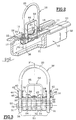
- Figure 2 shows the system 10 in position locking assembly.
- the locking members 52 of the combs 53 are carried by the longitudinal axis 50 which is immobilized in its transverse displacements by coaxial bores longitudinal 34 of the hooks 38 of the first slide 36, and is immobilized longitudinally by fixing means 51 such as elastic rings or, alternatively (not shown), a screw / nut system.
- the locking members 52 of the combs 53 are by elsewhere crossed by the longitudinal rod 62 which occupies a determined position in the slots 64 of the organs 52, of so that the upper parts of the locking members 52 of the combs 53 extend transversely outwards in the slide 16 between the teeth 17 of the rack 19.
- the locking members 52 are arranged alternately on the longitudinal axis 50, so that two organs 52 consecutive cooperate with two opposing spaces included between two teeth 17 of the rack 19.
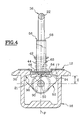
- Figure 4 shows the system 10 in position locked.
- the locking members 52 of the combs 53 have in the transverse plane P 'a profile in the form of a drop of water and are strung on axis 50 in the vicinity of their lower parts of larger dimensions 90. Their active upper parts 94 are received between the teeth 17 of the rack 19.
- the teeth 17 of the rack 19 views in the transverse plane P ' have a profile which is substantially triangular so as to favor the rapid extraction of locking members 52 of the combs 53 when these will, as will be described later, lead to retract.
- the teeth 17 of the rack 19 may have a profile in the form of parallelogram allowing better resistance to longitudinal efforts of the base 12.
- the slide 36 is therefore in the high position and the slide 56 is recalled in its low stop position on the axis 50 by the flat spring 67 shown in Figure 1, so that the longitudinal rod 62 is received in abutment at the end 96 of the lights 64 of the organs 52, which end 96 is opposite to the parts active 94 of said organs 52.
- the lights 64 are substantially in an arc and are not centered on axis 50.
- the distance E between the longitudinal rod 62 and the longitudinal axis 50 is minimal and the support of the rod longitudinal 62 in abutment at the bottom of the end 96 of the lights 64 keeps organs 52 in one position maximum transverse dimensions.
- Figure 5 illustrates the system configuration 10 when a user pushes the lashing ring 22 towards the bottom, as shown by the white arrow.
- the first slide 36 then occupies a position of low stop in which the active parts 94 of the organs locking 52 of the combs 53 are no longer received between teeth 17, but exposed below.
- the second slide descends with the first slide 36, since the spring 67 tends to return it towards the bottom and that the axis 50, forming a stop for the second slide solidly descends from the first slide 36.
- the locking members 52 of the combs 53 have maximum transverse dimensions, while being released from the teeth 17 of the rack 19.
- This position corresponds to a longitudinal adjustment position, by example, when a user wants to adjust the position longitudinal of the lashing ring 22, or of a possible vehicle interior sub-assembly which would be linked to the base 12.
- the weight of the base 12 and the sub all of the vehicle's interior fittings possibly linked plate the base 12 against the wings upper 30 of the slide 16 via the pads 28 and wings 24, and consequently the lashing ring 22 does not can move only longitudinally.
- the maximum transverse size of the locking members 52 of the combs 53 guarantees advantageously that it does not leave the slide 16 in the event that an effort is exerted vertically towards the high on the lashing ring 22, as would be the case if a load, secured to the ring 22 tipped during a violent shock.
- Figure 6 shows the system 10 in position vertical engagement or disengagement of the base 12.
- the longitudinal rod 62 has slipped inside lights 64 made in the locking members 52 of the combs 53 to reach a stop position 97, which is the opposite of the previous position 96 in the lights 64.
- the sliding bearing of the longitudinal rod 62 in the lights 64 of the organs 52 during the ascent of the slide 56 causes the inward transverse retraction of the organs 52, and the base 12 is no longer while resting on the wings 30 of the slide 16.
- the base 12 can then be removed of the slide 16.
- the ascent of the second slide 56 is perfectly ensured by the slots 58 of the base 12 and by the oblong holes 66 of the lower ends 54 of the second slide 56 which receive the longitudinal axis 50 integral with the first slide 36.
- this position corresponds to a use in engagement or release of the system 10 in the slide 16 linked to the vehicle.
- This position allows by example of removing or adding a subset such as previously described with reference to FIG. 1, so that ability to use the passenger compartment of the vehicle concerned with a great modularity.
- FIG. 7 also illustrates an embodiment as a variant of the slide 16.
- the rack 19 of the slide 16 is produced by two plates 98, hollowed out at intervals regular, and arranged in the longitudinal direction of the slide 16 and inclined at an angle similar to that of the teeth 17 described with reference to the preceding figures, for cooperate with hook ends 100 located at ends of the active parts 94 of the organs 52.
- the teeth 17 of the rack are made up by the areas of material between two recesses of the plates 98.
Landscapes
- Engineering & Computer Science (AREA)
- Aviation & Aerospace Engineering (AREA)
- Transportation (AREA)
- Mechanical Engineering (AREA)
- Surgical Instruments (AREA)
- Seats For Vehicles (AREA)
- Passenger Equipment (AREA)
- Body Structure For Vehicles (AREA)
- Lock And Its Accessories (AREA)
Claims (6)
- System (10) für die Einstellung der longitudinalen Position und die Blockierung in eingestellter Position einer Untergesamtheit an einer Karosseriestruktur eines Kraftfahrzeugs, welches mit mindestens einer Gleitschiene (16) ausgestattet ist, welche in longitudinaler Gleitbewegung mindestens eine Vorrichtung einer Führung von longitudinalen Verstellungen und einer longitudinalen und vertikalen Verriegelung einer Grundplatte (12) der Untergesamtheit in eingestellter Position aufnimmt, deren Ende, das in der Gleitschiene (16) aufgenommen ist, mit einem expandierbaren beweglichen Mechanismus ausgestattet ist, der gesteuert wird zwischenund von dem Typ, in welchem die zwei Verriegelungsorgane (53) des Mechanismus angelenkt um eine longitudinale Achse (50) an einem ersten Gleitstück (36) montiert sind, das vertikal beweglich bezüglich der Grundplatte (12) montiert ist, um die Organe (53) vertikal zu verstellen, und gesteuert sind zum Modifizieren ihres transversalen Raumbedarfs durch die vertikale Verstellung eines zweiten Gleitstücks (56), welches vertikal beweglich bezüglich dem ersten Gleitstück (36) montiert ist, und welches fest verbunden ist mit einer longitudinal ausgerichteten Stange (62), welche in Steuer-Langlöcher (64) der angelenkten Organe (53) aufgenommen wird, um unter ihrem vertikalen Annähern oder Entfernen von der longitudinalen Anlenkungsachse (50) der Organe (53) ihr Schwenken in den zwei Richtungen hervorzurufen,einer ersten extremen Position, bezeichnet als vertikale Eingriffs- oder Freigabeposition, in welcher zwei Verriegelungsorgane (53) des expandierbaren Mechanismus mit symmetrischer und im Verhältnis zu einer vertikalen Mittelebene P der Gleitschiene (16) gegenüberliegender Betätigung in einer eingezogenen Position in Richtung nach innen sind, in welcher ihr transversaler Raumbedarf das vertikale Einführen oder Herausbringen des Mechanismus über einen longitudinalen mittleren Spalt der Gleitschiene ermöglicht, der durch zwei obere, longitudinale und mit der Gleitschiene (16) parallele Flügel (30) begrenzt wird; undeiner zweiten extremen Position, bezeichnet als Verriegelungsposition, in welcher die zwei Organe (53) sich jedes transversal gegenüber von zwei inneren Flächen (21) der oberen. Flügel (30) der Gleitschiene (16) erstrecken, mit welchen sie durch Verhakung zusammenwirken, um die Grundplatte (12) bezüglich der Gleitschiene (16) longitudinal und vertikal festzusetzen;bei Hindurchgehen durch mindestens eine Zwischenposition, bezeichnet als Einstellposition, in welcher die zwei Organe (53) sich jedes transversal gegenüber der zwei inneren Flächen (21) der oberen Flügel 30 der Gleitschiene (16) erstrecken, um vertikal die Grundplatte (12) im Verhältnis zu der Gleitschiene (16) zu halten und longitudinale Verstellungen der Grundplatte (12) im Inneren der Gleitschiene (16) zu erlauben,
dadurch gekennzeichnet, dass die Untergesamtheit einen Befestigungsring (22) aufweist, und dass das erste Gleitstück (36) in seinen vertikalen Verstellungen durch manuelle vertikale Betätigungen an dem Befestigungsring (22) betätigt wird, welcher mit dem ersten Gleitstück (36) fest verbunden ist, und dass das zweite Gleitstück (56) in seinen vertikalen Verstellungen durch manuelle vertikale Betätigungen an einem Greifring (68) betätigt wird, der mit dem zweiten Gleitstück (56) fest verbunden ist. - System nach Anspruch 1, dadurch gekennzeichnet, dass das zweite Gleitstück (56) elastisch in Richtung zu einer unteren Position im Verhältnis zum ersten Gleitstück (36) zurückgeholt ist.
- System nach einem der vorhergehenden Ansprüche, dadurch gekennzeichnet, dass das erste Gleitstück (36) zwei zylindrische Zwischen-Führungssitze (44) aufweist, vertikal parallel und symmetrisch im Verhältnis zu einer vertikalen Mittelebene P' der Grundplatte (12), transversal zur Gleitschiene (16), welche gleitend in Langlöchern (20) der Grundplatte (12) mit komplementärem Durchmesser geführt sind, und das zweite Gleitstück zwei vertikale parallele und bezüglich der Mittelebene P' des ersten Gleitstücks (36) symmetrische Führungslappen (55) aufweist, und welche gleitend in Spalten (58) der Grundplatte (12) einer komplementären Form geführt sind.
- System nach irgendeinem der vorhergehenden Ansprüche, dadurch gekennzeichnet, dass die Verriegelungsorgane (53) gekrümmte, nicht um ihre Anlenkungsachse (50) zentrierte Langlöcher (64) aufweisen, welche einen vertikalen Lauf der Stange (62) bestimmen, welche durch das zweite Gleitstück (56) getragen wird und in den Langlöchem (64) in einer Weise aufgenommen ist, dass der Lauf der Stange (62) gleich dem Lauf des zweiten Gleitstücks (56) ist.
- System nach irgendeinem der vorhergehenden Ansprüche, dadurch gekennzeichnet, dass die Verriegelungsorgane (53) Kämme sind, von denen die aktiven Teile (94) zwischen transversalen Zähnen (17) von longitudinalen Zahnstangen (19) aufgenommen werden, welche durch die inneren Flächen (21) der oberen Flügel (30) der Gleitschiene getragen werden.
- System nach irgendeinem der Ansprüche 1 bis 4, dadurch gekennzeichnet, dass die Verriegelungsorgane (53) Kämme sind und die Gleitschiene eine Zahnstange (19) aufweist, welche durch Platten (98) realisiert ist, welche bei regelmäßigen Intervallen ausgespart sind und von einer komplementären Form von Haken (100), welche durch die aktiven Teile (94) der Kämme (53) getragen sind, um transversal in Richtung nach innen die seitlichen Wände (32) der Gleitschiene (16) zu schließen, wenn die Grundplatte (12) einer Kraft eines Herausreißens ausgesetzt wird.
Applications Claiming Priority (2)
| Application Number | Priority Date | Filing Date | Title |
|---|---|---|---|
| FR9804243 | 1998-04-06 | ||
| FR9804243A FR2777048B1 (fr) | 1998-04-06 | 1998-04-06 | Systeme modulable d'arrimage dans l'habitacle d'un vehicule automobile |
Publications (2)
| Publication Number | Publication Date |
|---|---|
| EP0949112A1 EP0949112A1 (de) | 1999-10-13 |
| EP0949112B1 true EP0949112B1 (de) | 2004-03-17 |
Family
ID=9524895
Family Applications (1)
| Application Number | Title | Priority Date | Filing Date |
|---|---|---|---|
| EP19990400817 Expired - Lifetime EP0949112B1 (de) | 1998-04-06 | 1999-04-02 | Modulares Befestigungssystem im Innenraum eines Kraftfahrzeuges |
Country Status (4)
| Country | Link |
|---|---|
| EP (1) | EP0949112B1 (de) |
| DE (1) | DE69915529T2 (de) |
| ES (1) | ES2213988T3 (de) |
| FR (1) | FR2777048B1 (de) |
Families Citing this family (11)
| Publication number | Priority date | Publication date | Assignee | Title |
|---|---|---|---|---|
| GB9927855D0 (en) * | 1999-11-26 | 2000-01-26 | Johnson Controls Gmbh | Anchor assembly |
| FR2856018B1 (fr) * | 2003-06-10 | 2005-08-26 | Faurecia Sieges Automobile | Dispositif de fixation d'un siege sur un plancher de vehicule et siege de vehicule comprenant un tel dispositif de fixation |
| FR2950292B1 (fr) * | 2009-09-21 | 2011-12-16 | Antolin Grupo Ing Sa | Dispositif d'ancrage de siege amovible de vehicule automobile |
| DE102011075771A1 (de) * | 2011-05-12 | 2012-11-15 | Airbus Operations Gmbh | Vorrichtung zur Befestigung von Sitzen in Passagierkabinen, Sitzschiene, Halteeinrichtung und Verfahren |
| FR2986751B1 (fr) * | 2012-02-10 | 2014-03-21 | Antolin Grupo Ing Sa | Mecanisme d'ancrage d'un siege amovible |
| DE102012218762A1 (de) * | 2012-09-06 | 2014-03-06 | Burg Silvergreen Gmbh | Vorrichtung zur sicherung von ladegut |
| ITTO20130320A1 (it) * | 2013-04-22 | 2014-10-23 | Ruspa Officine S P A | Sedile per veicolo di tipo scorrevole |
| EP3150426B1 (de) * | 2015-10-02 | 2018-07-25 | Tillmann Profil GmbH | Schiene für einen sitz eines kraftfahrzeuges sowie sitzschienensystem für ein kraftfahrzeug |
| CN107399348B (zh) * | 2017-08-01 | 2023-08-11 | 上汽大众汽车有限公司 | 一种汽车电池的搬运工具 |
| DE102019120194A1 (de) | 2019-07-25 | 2021-01-28 | Aguti Produktentwicklung & Design Gmbh | Vorrichtung zur Anbringung einer Sitzanordnung in einem Fahrzeug und Fahrzeug |
| CN114537232B (zh) * | 2022-02-14 | 2025-06-03 | 江苏忠明祥和精工股份有限公司 | 一种车辆座椅用长滑轨装置 |
Family Cites Families (5)
| Publication number | Priority date | Publication date | Assignee | Title |
|---|---|---|---|---|
| US3486204A (en) * | 1967-07-26 | 1969-12-30 | Mc Donnell Douglas Corp | Seat pallet latch |
| US5236153A (en) * | 1992-06-25 | 1993-08-17 | Laconte Richard J | Longitudinal floating pivot track fitting |
| DE19633032B4 (de) * | 1995-08-25 | 2007-01-04 | Volkswagen Ag | Befestigungssystem |
| DE29611382U1 (de) * | 1996-06-29 | 1997-12-11 | Illies GmbH, 38667 Bad Harzburg | Gepaeckbox fuer kraftfahrzeuge |
| DE29803620U1 (de) * | 1998-03-03 | 1998-05-07 | Fairchild Fasteners Europe - Camloc GmbH, 65779 Kelkheim | Sitzbefestigung |
-
1998
- 1998-04-06 FR FR9804243A patent/FR2777048B1/fr not_active Expired - Fee Related
-
1999
- 1999-04-02 EP EP19990400817 patent/EP0949112B1/de not_active Expired - Lifetime
- 1999-04-02 DE DE69915529T patent/DE69915529T2/de not_active Expired - Lifetime
- 1999-04-02 ES ES99400817T patent/ES2213988T3/es not_active Expired - Lifetime
Also Published As
| Publication number | Publication date |
|---|---|
| EP0949112A1 (de) | 1999-10-13 |
| FR2777048B1 (fr) | 2000-06-02 |
| ES2213988T3 (es) | 2004-09-01 |
| FR2777048A1 (fr) | 1999-10-08 |
| DE69915529T2 (de) | 2005-03-03 |
| DE69915529D1 (de) | 2004-04-22 |
Similar Documents
| Publication | Publication Date | Title |
|---|---|---|
| EP0363261B1 (de) | Verstärkte Armatur für Fahrzeugsitze | |
| EP0947380B1 (de) | Auf dem Schienenboden eingebaute Zahnstangenvorrichtung | |
| EP0949111B1 (de) | Modulares Befestigungssystem mit Nockensteuerung | |
| EP0949112B1 (de) | Modulares Befestigungssystem im Innenraum eines Kraftfahrzeuges | |
| FR2774045A1 (fr) | Siege pour vehicule, amovible, retournable et reglable longitudinalement | |
| FR2789026A1 (fr) | Siege de vehicule comportant une traverse de securite mobile | |
| FR2869857A1 (fr) | Guide de sangle de ceinture de securite | |
| FR2673148A1 (fr) | Siege amovible de vehicule. | |
| FR2725946A1 (fr) | Cale a rapporter sur un plan porteur presentant des perforations | |
| FR2675442A1 (fr) | Dispositif permettant de mettre en place sans outillage des points de fixation pour le positionnement et l'ancrage solides d'une charge. | |
| FR2694971A1 (fr) | Poulie coupée, notamment pour bateaux à voiles. | |
| EP0532378B1 (de) | Rückhaltevorrichtung für einen, auf dem mittleren Rücksitz eines Fahrzeuges sitzenden, Insassen | |
| FR2963587A1 (fr) | Systeme d'accoudoir pour habitacle de vehicule | |
| FR2651733A1 (fr) | Dispositif de reglage de ceinture pour ceinture de securite de siege. | |
| FR2930485A1 (fr) | Siege automobile pour enfant | |
| FR2716423A1 (fr) | Dispositif de sécurité intégré à un siège de véhicule. | |
| FR2810929A1 (fr) | Dispositif d'assise pour vehicule | |
| EP0437413B1 (de) | Verschiebbare einheitliche Struktur zur Befestigung oder zum Unterstützen von Fahrzeugrädern | |
| EP0457699A2 (de) | Vorrichtung zum automatischen Kuppeln einer Sicherheitsgurtverankerung mit dem Boden eines Fahrzeuges | |
| FR3016146A1 (fr) | Glissiere et siege de vehicule automobile comportant une telle glissiere | |
| FR3021001A1 (fr) | Vehicule automobile comportant des supports de siege retractables | |
| EP1097846A1 (de) | System zur Befestigung von Gegenständen im Inneren eines Kraftfahrzeugs sowie gleitende Ankerelemente hierfür | |
| FR2562004A1 (fr) | Glissiere permettant le reglage longitudinal d'un siege pour des vehicules terrestre, nautique et aerien | |
| EP0543706A1 (de) | Vorrichtung zum automatischen Kuppeln einer Sicherheitsgurtverankerung mit dem Boden eines Fahrzeuges | |
| WO2016030639A1 (fr) | Siège pour véhicule comprenant un plancher de chargement |
Legal Events
| Date | Code | Title | Description |
|---|---|---|---|
| PUAI | Public reference made under article 153(3) epc to a published international application that has entered the european phase |
Free format text: ORIGINAL CODE: 0009012 |
|
| AK | Designated contracting states |
Kind code of ref document: A1 Designated state(s): AT BE CH CY DE DK ES FI FR GB GR IE IT LI LU MC NL PT SE |
|
| AX | Request for extension of the european patent |
Free format text: AL;LT;LV;MK;RO;SI |
|
| 17P | Request for examination filed |
Effective date: 20000405 |
|
| AKX | Designation fees paid |
Free format text: DE ES GB IT |
|
| RAP1 | Party data changed (applicant data changed or rights of an application transferred) |
Owner name: RENAULT S.A.S. |
|
| GRAH | Despatch of communication of intention to grant a patent |
Free format text: ORIGINAL CODE: EPIDOS IGRA |
|
| GRAS | Grant fee paid |
Free format text: ORIGINAL CODE: EPIDOSNIGR3 |
|
| GRAA | (expected) grant |
Free format text: ORIGINAL CODE: 0009210 |
|
| AK | Designated contracting states |
Kind code of ref document: B1 Designated state(s): DE ES GB IT |
|
| REG | Reference to a national code |
Ref country code: GB Ref legal event code: FG4D Free format text: NOT ENGLISH |
|
| REF | Corresponds to: |
Ref document number: 69915529 Country of ref document: DE Date of ref document: 20040422 Kind code of ref document: P |
|
| GBT | Gb: translation of ep patent filed (gb section 77(6)(a)/1977) |
Effective date: 20040715 |
|
| REG | Reference to a national code |
Ref country code: ES Ref legal event code: FG2A Ref document number: 2213988 Country of ref document: ES Kind code of ref document: T3 |
|
| PLBE | No opposition filed within time limit |
Free format text: ORIGINAL CODE: 0009261 |
|
| STAA | Information on the status of an ep patent application or granted ep patent |
Free format text: STATUS: NO OPPOSITION FILED WITHIN TIME LIMIT |
|
| 26N | No opposition filed |
Effective date: 20041220 |
|
| PGFP | Annual fee paid to national office [announced via postgrant information from national office to epo] |
Ref country code: DE Payment date: 20120420 Year of fee payment: 14 |
|
| PGFP | Annual fee paid to national office [announced via postgrant information from national office to epo] |
Ref country code: GB Payment date: 20120419 Year of fee payment: 14 |
|
| PGFP | Annual fee paid to national office [announced via postgrant information from national office to epo] |
Ref country code: IT Payment date: 20120424 Year of fee payment: 14 |
|
| PGFP | Annual fee paid to national office [announced via postgrant information from national office to epo] |
Ref country code: ES Payment date: 20120425 Year of fee payment: 14 |
|
| GBPC | Gb: european patent ceased through non-payment of renewal fee |
Effective date: 20130402 |
|
| PG25 | Lapsed in a contracting state [announced via postgrant information from national office to epo] |
Ref country code: GB Free format text: LAPSE BECAUSE OF NON-PAYMENT OF DUE FEES Effective date: 20130402 Ref country code: DE Free format text: LAPSE BECAUSE OF NON-PAYMENT OF DUE FEES Effective date: 20131101 |
|
| REG | Reference to a national code |
Ref country code: DE Ref legal event code: R119 Ref document number: 69915529 Country of ref document: DE Effective date: 20131101 |
|
| PG25 | Lapsed in a contracting state [announced via postgrant information from national office to epo] |
Ref country code: IT Free format text: LAPSE BECAUSE OF NON-PAYMENT OF DUE FEES Effective date: 20130402 |
|
| REG | Reference to a national code |
Ref country code: ES Ref legal event code: FD2A Effective date: 20150710 |
|
| PG25 | Lapsed in a contracting state [announced via postgrant information from national office to epo] |
Ref country code: ES Free format text: LAPSE BECAUSE OF NON-PAYMENT OF DUE FEES Effective date: 20130403 |