EP0949140A2 - Side-car de bicyclette - Google Patents
Side-car de bicyclette Download PDFInfo
- Publication number
- EP0949140A2 EP0949140A2 EP99106601A EP99106601A EP0949140A2 EP 0949140 A2 EP0949140 A2 EP 0949140A2 EP 99106601 A EP99106601 A EP 99106601A EP 99106601 A EP99106601 A EP 99106601A EP 0949140 A2 EP0949140 A2 EP 0949140A2
- Authority
- EP
- European Patent Office
- Prior art keywords
- frame
- wheel
- sidecar
- support wheel
- wheeled vehicle
- Prior art date
- Legal status (The legal status is an assumption and is not a legal conclusion. Google has not performed a legal analysis and makes no representation as to the accuracy of the status listed.)
- Withdrawn
Links
Images




Classifications
-
- B—PERFORMING OPERATIONS; TRANSPORTING
- B62—LAND VEHICLES FOR TRAVELLING OTHERWISE THAN ON RAILS
- B62K—CYCLES; CYCLE FRAMES; CYCLE STEERING DEVICES; RIDER-OPERATED TERMINAL CONTROLS SPECIALLY ADAPTED FOR CYCLES; CYCLE AXLE SUSPENSIONS; CYCLE SIDECARS, FORECARS, OR THE LIKE
- B62K27/00—Sidecars; Forecars; Trailers or the like specially adapted to be attached to cycles
Definitions
- the invention relates to a two-wheeled vehicle with a sidecar, in particular a bicycle with a sidecar according to the preamble of claim 1.
- a known, generic two-wheeled vehicle with sidecar as Bicycle with sidecar consists of a two-wheeled frame with a front wheel and rear wheel running in a first lane, from which the front wheel can be steered.
- the sidecar consists of one Sidecar frame, on which a second track on a jockey wheel axle running jockey wheel is attached.
- the sidecar frame is with the two-wheeled frame over a running in the vehicle longitudinal direction Swivel axis pivotally connected.
- the pivot axis lies here the side car side or on the bicycle side, on which the side car runs with his jockey wheel.
- the jockey wheel is forcibly coupled into the opposite when cornering Inclined towards the rear wheel inclination of the two-wheeled vehicle. This would make the rear wheel of the two-wheeled vehicle and that Jockey wheel without the mutual connection by two far apart Curve centers run through what is actually connected leads to considerable constraining forces when cornering. So here is one uncomfortable, getting used to driving feeling for both the two-wheel drive as well as for one person in the sidecar, whereby also the controllability of the team and driving safety negatively affected are.
- the object of the invention is to provide a generic two-wheeled vehicle to develop a sidecar so that with a good driving experience Driving safety is increased.
- the pivot axis is on the two-wheeled vehicle side not facing the sidecar with a lateral distance to the wheel center plane.
- the pivot axis in a plan view to the rear by a first angle [ ⁇ ] to be inclined sideways on the outside in relation to the vehicle's longitudinal direction.
- This measure ensures that the rear swivel axis area relatively far to the side outside of the two-wheel vehicle longitudinal vertical plane is offset. This takes place when cornering with inclined Two-wheeler vehicle an advantageous large increase or decrease in Pivot axis, so that the advantages mentioned above occur more.
- the angle [ ⁇ ] is not too large is selected and the usual inclination angle for two-wheeled vehicles approximately in Maximum range of ⁇ 30 ° [usual clearance angle for pedals and attachments] to be viewed as.
- the second angle [ ⁇ ] turns in both directions when cornering each automatically a correct angle for the jockey wheel set. This further reduces constraining forces when cornering, because the center of the curves of the rear wheel of the two-wheeled vehicle and the jockey wheel are further adjusted.
- FIG. 4 With the features of claim 4 is a two-wheeled vehicle with a Side frame claimed, in which the support edge with its support wheel axis pivotally held on the sidecar frame and over a Tilt coupling device is connected to the two-wheeled vehicle.
- Power transmission means can be advantageous in the tilt coupling device at least one cable or two articulated levers in the manner of a four-bar linkage be used. Even with such an arrangement, the above-mentioned.
- a such sidecar frame can in particular be a basis for a transport area or preferably form for a children's compartment.
- the team arrangement described is basically suitable for everyone Two-wheeled vehicles with sidecars. According to claim 6, however, is a preferred use seen in connection with bicycles. Even slightly motorized Bicycles with auxiliary engines, mopeds, etc. are suitable, however the arrangement in connection with more motorized motorcycles less can be considered.
- the holder for the connecting longitudinal member is simple and inexpensive thanks to one with the two-wheeled frame constantly and firmly Connected pipe receptacle can be produced, in which the free end of the connecting side member releasably inserted by means of a snap lock can.
- This can be structurally simple with the bracket Swivel axis are formed in the bracket.
- the support wheel can according to claim 8 in a conventional manner in a holding frame to be appropriate.
- a foldable Sidecar suggested that when not in use in this position can be locked, so that then the two-wheeled vehicle in the usual Is usable or space-saving together with the sidecar if necessary can be turned off.
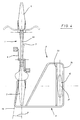
- the bike 1 and 2 is a first embodiment of a team a bicycle 1 and a sidecar 2 shown.
- the bike 1 exists in the usual way from a bicycle frame 3, one with a Handlebar 4 steerable front wheel 5, one driven by a pedals 6 Rear wheel 7 and a bicycle seat 8 for a combination handlebar.
- the sidecar consists of a sidecar frame 9, which with the Bicycle frame 3 is connected and on which a sidecar exterior Jockey wheel 10 is attached.
- the sidecar frame 9 has a top view from above [Fig. 2] a U-frame shape in the basic structure.
- a U-frame leg is designed as a connecting longitudinal beam 11 and after directed towards the front in the longitudinal direction of the bicycle. With its front end it is on the bicycle wheel opposite the support wheel 10 via a bracket 12 releasably connected directly or indirectly to the bicycle frame 3.
- the bracket 12 consists of one with the bicycle frame 3 firmly connected pipe receptacle 13, in or over which the connecting longitudinal member 11 is releasably inserted with the aid of a snap lock 14.
- the U-frame base runs as a base cross member 16 behind the rear wheel 7 to the second U-frame leg arrangement as Jockey wheel side member 18.
- a diagonal support 20 is provided [Fig. 2], which may can be supplemented by further [not shown] carriers.
- the support wheel 10 is about 2/3 the size of the rear wheel 7, so that the Base cross member 16 in the area of the rear wheel 7 down to about Height of the support wheel axis 17 is cranked. As can be seen from Fig. 2, lie the rear wheel axis 21 and the support wheel axis 17 in a transverse vertical plane 22.
- the jockey wheel longitudinal member 18 is formed in several parts and consists of one Top view of one through two, approximately parallel longitudinal support beam parts 23, 24 laterally limited holding frame 25.
- the support wheel 10 runs between these two longitudinal support beam parts 23, 24 [in the first embodiment 1 and 2] in a swivel frame 26, the support wheel axis 17 on opposite frame parts 27, 28 of the swivel frame 26 is attached.
- the sidecar outer frame part 28 of the Swing frame 26 forms a central part of the sidecar exterior Jockey wheel longitudinal member part 24.
- the frame part 28 is there in the longitudinal direction protruding extensions 29, 30 in adjacent carrier parts of the sidecar outer support wheel longitudinal member 24 inserted. This will a longitudinally aligned support wheel pivot axis 31 for a pivotable bracket of the support wheel 10 created.
- the rear cross member 32 of the holding frame 35 is via a screw connection 33 connected to the base cross member 16. This will on the one hand, when mounting the cross member 32, the pivotable plug connection between the holding frame 25 and the swivel frame 26 producible.
- the cross member 32 in the transverse direction relative to the base cross member 16, for example an elongated hole arrangement on the screw connection 33 within certain limits the toe-in of the support wheel 10 is set for a basic setting become.
- the tilt coupling device 34 consists essentially from a cable 35, on the one hand via a holding device, not shown 36 detachable at rear wheel axle height opposite the first Swivel axis 15 indirectly or directly with the bicycle frame 3 connected is.
- the cable 35 is based on the holding device 36 diagonally down over a first roller 37 and then horizontally under the Sidecar frame 9 led to a second roller 38 and then runs diagonally upwards to a junction 39 on the inside of the sidecar Frame part 27 of the swivel frame 26.
- the cable 35 is indirect with the inside of the sidecar part of the swiveling Support wheel axis 17 connected.
- the second pivot axis 31 laterally by a distance 41 outside as the wheel contact point 42 of the support wheel 10 loaded sidecar 2 on the support wheel 10 a torque [arrow 43], that causes a tension force on the cable 35.
- the sidecar has the bike in the usual way 1 and thus the rear wheel 7 to compensate for centrifugal forces to the left inclined.
- the pivotable connection on the center of gravity 15 follows the sidecar frame 9 of this inclination.
- the cable 35 is against it pulled to the left by lifting the holder 36, thereby the connection point 39 down against the restoring torque [Arrow 43] is pulled.
- This rope tensioning torque can be used if necessary supported by the installation of a spring device [not shown] become. So that the swing frame 26 by the cable is around the second Swivel axis 31 has been pivoted downward, so that the inclination of the Bicycle 1, or the rear wheel 7 coupled in the same direction to the support wheel 10 has been. With a right-hand bend, the coupling takes place in the opposite direction Direction.
- 3 to 8 relate to a second embodiment of a team that essentially in the structure of the first embodiment of a team corresponds so that the reference numerals used there also for the second Embodiment can be used.
- the second embodiment differs differs from the first embodiment in that the support wheel 10 is not pivotally mounted on the support wheel side member 18 but is stationary and the pivot axis 15 is inclined to the longitudinal direction of the bicycle 44 and a horizontal plane 45.
- the axis of gravity 15 is, on the one hand, in a plan view corresponding to FIG. 4 by a first angle [ ⁇ ] to the rear outward in relation to the longitudinal direction of the bicycle 44 inclined and also, as seen from the side view Fig. 7 can be seen by a second angle [ ⁇ ] towards the bottom opposite the horizontal plane 45 inclined.
- FIG. 7 shows a preferred embodiment to recognize a bracket 12, in which a pipe receptacle 13 along a rear fork up to the front to form stable frame parts is guided and attached.
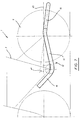
- Fig. 6 the team of Fig. 4 is shown with a certain steering angle of the front wheel 5 for a right turn.
- the rear wheel 7 would run on an arc K1 and the support wheel parallel to it on a smaller arc K1 ', the arcs being the same [no longer have on the drawing sheet] center, to which a radius ray r 1 is drawn.
- the bicycle 3 can pivot axis 15 in the manner shown in FIG. 5 be inclined to compensate for centrifugal forces. Because of this tendency becomes a narrower with both the rear wheel 7 and the support wheel 10 Circular arc moved according to K2 and K2 'around a circle center M2. This is due to the side inclination in the right curve shown the rear swivel axis area 46 is raised relative to the basic position, whereby the sidecar 2 with the children's compartment 19 and the Jockey wheel 10 is inclined towards the middle of the curve [corresponding to the inclined Line 47]. Due to the inclination of the rear wheel 7 Coupled inclination of the support wheel 10 takes place an adjustment the assigned center positions so that constraining forces are reduced.
- FIG. 8 corresponds to the illustration according to FIG. 6, the circular arcs K1 'and K2' with the associated radii r 1 and r 2 also being drawn in FIG. 8.
- Angle [ ⁇ ] is with a right curve and a right side slope of the Bicycle 1, the support wheel 10 by the lead angle shown in Fig. 8 [ ⁇ ] pivoted outwards, which further constraining forces when cornering [ ⁇ ] can be reduced by the center positions of the curves of the Rear wheel 7 and the support wheel 10 are further aligned.
- the lead angle [ ⁇ ] shown is also advantageously the sidecar 2 when turning right from bike 1 slightly pivoted so that for the trailer Advantageously more space, especially in the area of the pedals is created.
- the left turns when [not shown] Lead angle [ ⁇ ] in the correct position to the other side and results in the corresponding Advantages.
Landscapes
- Engineering & Computer Science (AREA)
- Transportation (AREA)
- Mechanical Engineering (AREA)
- Motorcycle And Bicycle Frame (AREA)
- Automatic Cycles, And Cycles In General (AREA)
Applications Claiming Priority (2)
| Application Number | Priority Date | Filing Date | Title |
|---|---|---|---|
| DE1998116048 DE19816048A1 (de) | 1998-04-09 | 1998-04-09 | Zweirad-Fahrzeug mit Seitenwagen |
| DE19816048 | 1998-04-09 |
Publications (2)
| Publication Number | Publication Date |
|---|---|
| EP0949140A2 true EP0949140A2 (fr) | 1999-10-13 |
| EP0949140A3 EP0949140A3 (fr) | 2002-09-11 |
Family
ID=7864199
Family Applications (1)
| Application Number | Title | Priority Date | Filing Date |
|---|---|---|---|
| EP99106601A Withdrawn EP0949140A3 (fr) | 1998-04-09 | 1999-03-31 | Side-car de bicyclette |
Country Status (2)
| Country | Link |
|---|---|
| EP (1) | EP0949140A3 (fr) |
| DE (1) | DE19816048A1 (fr) |
Cited By (3)
| Publication number | Priority date | Publication date | Assignee | Title |
|---|---|---|---|---|
| RU2225312C2 (ru) * | 2002-04-15 | 2004-03-10 | Закрытое акционерное общество "РУСАН" | Крепежный продольный стержень для велосипеда с навесным оборудованием |
| WO2005077742A1 (fr) | 2004-01-19 | 2005-08-25 | Smike Ag | Deux-roues equipe d'un side-car |
| ITRN20100037A1 (it) * | 2010-06-23 | 2011-12-24 | Paolo Bianchi | Carrello appendice per biciclette |
Citations (5)
| Publication number | Priority date | Publication date | Assignee | Title |
|---|---|---|---|---|
| US1235177A (en) | 1913-07-21 | 1917-07-31 | Hugo H Young | Side car for motor-cycles. |
| FR811524A (fr) | 1936-09-30 | 1937-04-16 | Side-car pour bicyclette, vélo-moteur et motocyclette | |
| FR821313A (fr) | 1937-04-30 | 1937-12-02 | Châssis oscillant pour side-car | |
| FR919426A (fr) | 1945-12-27 | 1947-03-07 | Side-car à châssis pivotant et à roue s'inclinant parallèlement à la roue arrière de la motocyclette | |
| DE8000692U1 (de) | 1980-01-12 | 1980-04-17 | Schieferstein, Hermann, 4930 Detmold | Zweirad-fahrzeug mit beiwagen |
Family Cites Families (12)
| Publication number | Priority date | Publication date | Assignee | Title |
|---|---|---|---|---|
| DE621274C (de) * | 1935-11-04 | Ernst Oechler | Motorradbeiwagengestell | |
| DE377973C (de) * | 1923-06-30 | Louis Rustin | Verbindung zwischen Motorrad und seitlichem Beiwagen | |
| US1384300A (en) * | 1920-08-05 | 1921-07-12 | Buckland George Gardner | Bicycle side car |
| DE448172C (de) * | 1926-04-13 | 1927-08-06 | Mabeco Werke G M B H | Einrichtung zur Befestigung eines Beiwagens an einem Motorrad |
| DE467256C (de) * | 1927-01-12 | 1928-10-20 | Gottfried Koehler | Gelenkig mit dem Motorrad verbundener Seitenwagen |
| DE630563C (de) * | 1934-07-20 | 1936-05-30 | Ludwig Mankher | Beiwagen fuer Fahrraeder |
| DE653178C (de) * | 1935-04-23 | 1937-11-19 | Fritz Striedinger | Schwenkrad fuer Motorradbeiwagen |
| DE687584C (de) * | 1937-11-28 | 1940-02-01 | Erich Franke | Kraftrad mit Seitenwagen |
| US3013814A (en) * | 1958-06-16 | 1961-12-19 | Donald A Becks | Side-cart attachment for bicycles |
| DE3711554A1 (de) * | 1987-04-06 | 1988-10-27 | Isdera Ing Buero Eberhard Schu | Kurvenneigbares zweispurfahrzeug |
| DE3915097A1 (de) * | 1989-05-09 | 1990-11-15 | Roland Richter | Fahrrad mit beiwagen |
| DE9415146U1 (de) * | 1994-09-19 | 1995-01-26 | E.M.L. Holland BV, Neede | Seitenwagen mit Schwinge |
-
1998
- 1998-04-09 DE DE1998116048 patent/DE19816048A1/de not_active Withdrawn
-
1999
- 1999-03-31 EP EP99106601A patent/EP0949140A3/fr not_active Withdrawn
Patent Citations (5)
| Publication number | Priority date | Publication date | Assignee | Title |
|---|---|---|---|---|
| US1235177A (en) | 1913-07-21 | 1917-07-31 | Hugo H Young | Side car for motor-cycles. |
| FR811524A (fr) | 1936-09-30 | 1937-04-16 | Side-car pour bicyclette, vélo-moteur et motocyclette | |
| FR821313A (fr) | 1937-04-30 | 1937-12-02 | Châssis oscillant pour side-car | |
| FR919426A (fr) | 1945-12-27 | 1947-03-07 | Side-car à châssis pivotant et à roue s'inclinant parallèlement à la roue arrière de la motocyclette | |
| DE8000692U1 (de) | 1980-01-12 | 1980-04-17 | Schieferstein, Hermann, 4930 Detmold | Zweirad-fahrzeug mit beiwagen |
Cited By (4)
| Publication number | Priority date | Publication date | Assignee | Title |
|---|---|---|---|---|
| RU2225312C2 (ru) * | 2002-04-15 | 2004-03-10 | Закрытое акционерное общество "РУСАН" | Крепежный продольный стержень для велосипеда с навесным оборудованием |
| WO2005077742A1 (fr) | 2004-01-19 | 2005-08-25 | Smike Ag | Deux-roues equipe d'un side-car |
| ITRN20100037A1 (it) * | 2010-06-23 | 2011-12-24 | Paolo Bianchi | Carrello appendice per biciclette |
| EP2399816A1 (fr) * | 2010-06-23 | 2011-12-28 | Antonio Guagneli | Chariot supplémentaire pour bicyclettes |
Also Published As
| Publication number | Publication date |
|---|---|
| DE19816048A1 (de) | 1999-10-21 |
| EP0949140A3 (fr) | 2002-09-11 |
Similar Documents
| Publication | Publication Date | Title |
|---|---|---|
| DE60130729T2 (de) | Fahrzeug | |
| DE10041046B4 (de) | Aufhängungssystem für Fahrzeuge | |
| DE69834552T2 (de) | Fahrradaufhängungsvorrichtung | |
| DE102016120697B4 (de) | Auflieger-Lastenfahrrad | |
| EP3205564A2 (fr) | Vélo cargo | |
| DE4435482A1 (de) | Hinterradaufhängung für Zweiräder | |
| DE1931118U (de) | Mehrraedriges fahrzeug. | |
| DE102019116944B4 (de) | Fahrzeug mit Vorderradantrieb | |
| WO2022012783A1 (fr) | Véhicule à trois roues ayant un cadre en plusieurs parties | |
| DE4311998C2 (de) | Zusammenlegbarer Fahrradrahmen | |
| DE20206975U1 (de) | Fahrrad | |
| WO1995002521A1 (fr) | Vehicule leger dirigeable a roues alignees ou non, actionne par la force musculaire et/ou par moteur | |
| DE9212885U1 (de) | Kupplung zum Anhängen eines Fahrradanhängers an einem Fahrradrahmen | |
| DE3711554A1 (de) | Kurvenneigbares zweispurfahrzeug | |
| EP0586754A1 (fr) | Cadres pour véhicules à voie unique, en particulière bicyclettes | |
| DE4244206A1 (de) | Vorrichtung zur Verbindung zweier Fahrräder | |
| WO2001002240A1 (fr) | Bicyclette | |
| DE4325274C2 (de) | Fahrrad | |
| DE10224289B4 (de) | Fahrzeug, angetrieben mit Brennkraftmaschine oder Elektromotor | |
| EP0679568B1 (fr) | Véhicule à trois roues | |
| DE102019118235B3 (de) | Fahrzeug mit Pedalantrieb | |
| DE19533669A1 (de) | Leichtfahrzeug | |
| DE19816048A1 (de) | Zweirad-Fahrzeug mit Seitenwagen | |
| EP4467431B1 (fr) | Véhicule léger, notamment vélo de transport | |
| DE102016115442B3 (de) | Liege- oder Sesselfahrrad mit zwei parallel zueinander angeordneten Vorderrädern und Lenkung und Längsrahmen für ein solches Liege- oder Sesselfahrrad |
Legal Events
| Date | Code | Title | Description |
|---|---|---|---|
| PUAI | Public reference made under article 153(3) epc to a published international application that has entered the european phase |
Free format text: ORIGINAL CODE: 0009012 |
|
| AK | Designated contracting states |
Kind code of ref document: A2 Designated state(s): AT BE CH CY DE DK ES FI FR GB GR IE IT LI LU MC NL PT SE |
|
| AX | Request for extension of the european patent |
Free format text: AL;LT;LV;MK;RO;SI |
|
| PUAL | Search report despatched |
Free format text: ORIGINAL CODE: 0009013 |
|
| AK | Designated contracting states |
Kind code of ref document: A3 Designated state(s): AT BE CH CY DE DK ES FI FR GB GR IE IT LI LU MC NL PT SE |
|
| AX | Request for extension of the european patent |
Free format text: AL;LT;LV;MK;RO;SI |
|
| AKX | Designation fees paid | ||
| REG | Reference to a national code |
Ref country code: DE Ref legal event code: 8566 |
|
| STAA | Information on the status of an ep patent application or granted ep patent |
Free format text: STATUS: THE APPLICATION IS DEEMED TO BE WITHDRAWN |
|
| 18D | Application deemed to be withdrawn |
Effective date: 20030312 |