EP0949183A2 - Mécanisme de translation, en particulier pour appareils de levage et charges suspendues - Google Patents
Mécanisme de translation, en particulier pour appareils de levage et charges suspendues Download PDFInfo
- Publication number
- EP0949183A2 EP0949183A2 EP99250093A EP99250093A EP0949183A2 EP 0949183 A2 EP0949183 A2 EP 0949183A2 EP 99250093 A EP99250093 A EP 99250093A EP 99250093 A EP99250093 A EP 99250093A EP 0949183 A2 EP0949183 A2 EP 0949183A2
- Authority
- EP
- European Patent Office
- Prior art keywords
- motor
- time
- time constant
- stationary
- chassis
- Prior art date
- Legal status (The legal status is an assumption and is not a legal conclusion. Google has not performed a legal analysis and makes no representation as to the accuracy of the status listed.)
- Granted
Links
- 230000008859 change Effects 0.000 claims description 16
- 238000000034 method Methods 0.000 claims description 16
- 230000005526 G1 to G0 transition Effects 0.000 claims description 9
- 230000008569 process Effects 0.000 claims description 8
- 230000002123 temporal effect Effects 0.000 claims description 6
- 239000000969 carrier Substances 0.000 description 7
- 230000000694 effects Effects 0.000 description 3
- 230000008901 benefit Effects 0.000 description 2
- 238000005096 rolling process Methods 0.000 description 2
- 230000015572 biosynthetic process Effects 0.000 description 1
- 230000001419 dependent effect Effects 0.000 description 1
- 230000003993 interaction Effects 0.000 description 1
- 230000009467 reduction Effects 0.000 description 1
- 230000000284 resting effect Effects 0.000 description 1
- 239000000725 suspension Substances 0.000 description 1
Images

Classifications
-
- B—PERFORMING OPERATIONS; TRANSPORTING
- B66—HOISTING; LIFTING; HAULING
- B66D—CAPSTANS; WINCHES; TACKLES, e.g. PULLEY BLOCKS; HOISTS
- B66D1/00—Rope, cable, or chain winding mechanisms; Capstans
- B66D1/28—Other constructional details
- B66D1/40—Control devices
-
- B—PERFORMING OPERATIONS; TRANSPORTING
- B66—HOISTING; LIFTING; HAULING
- B66C—CRANES; LOAD-ENGAGING ELEMENTS OR DEVICES FOR CRANES, CAPSTANS, WINCHES, OR TACKLES
- B66C9/00—Travelling gear incorporated in or fitted to trolleys or cranes
- B66C9/14—Trolley or crane travel drives
-
- B—PERFORMING OPERATIONS; TRANSPORTING
- B66—HOISTING; LIFTING; HAULING
- B66C—CRANES; LOAD-ENGAGING ELEMENTS OR DEVICES FOR CRANES, CAPSTANS, WINCHES, OR TACKLES
- B66C11/00—Trolleys or crabs, e.g. operating above runways
- B66C11/02—Trolleys or crabs, e.g. operating above runways with operating gear or operator's cabin suspended, or laterally offset, from runway or track
- B66C11/04—Underhung trolleys
- B66C11/06—Underhung trolleys running on monorails
-
- B—PERFORMING OPERATIONS; TRANSPORTING
- B66—HOISTING; LIFTING; HAULING
- B66C—CRANES; LOAD-ENGAGING ELEMENTS OR DEVICES FOR CRANES, CAPSTANS, WINCHES, OR TACKLES
- B66C9/00—Travelling gear incorporated in or fitted to trolleys or cranes
- B66C9/18—Travelling gear incorporated in or fitted to trolleys or cranes with means for locking trolleys or cranes to runways or tracks to prevent inadvertent movements
Definitions
- the invention relates to a method and a chassis according to the preambles of Claims 1 and 6.
- a generic chassis is known that one Flange parts and web parts includes existing rail.
- On this chassis is a pair of impellers are provided which face each other on the Support the inside of the lower flange.
- the leaders are in front and behind the Guide wheels arranged on both sides on the side surfaces of the lower one Dock.
- the wheels and the guide rollers are pivoted on spars that are interconnected below the rail.
- the chassis is driven in that one of the impellers can be driven by a motor via a worm is.
- guides arranged in which the guide wheels of the chassis to run.
- the solution provides for a self-locking Worm gear chassis after switching on a stationary Motor voltage (U0) each have a start-up time constant during the start-up process from the reciprocal mean temporal increase in engine torque (M) multiplied by the motor torque (M0) of the stationary phase and that the engine torque (M) is reduced so that the chassis the instantaneous change in engine torque (M) over time (t) with a time constant that is greater than the start-up time constant.
- the effective self-locking and the associated braking effect steadily so that there is no locking of the wheels.
- the Deceleration of the chassis set by changing the engine torque so that an effect similar to that of a traction drive with a flywheel and mechanical brake is achieved.
- the engine torque reduction in Interaction with the self-locking worm gear has the same effect like turning on the brake on a traction drive with a flywheel, namely a soft braking without rolling movements, but with the advantage that no brake has to be readjusted and maintained and that on the space-intensive and costly attachment of the flywheel usually required can be dispensed with.
- the process can be carried out simply if the start-up time constant is from the mean temporal change in the current consumption in a predetermined time interval (t1, t2), which occurs between the switch-on time and the time until it is reached of the stationary motor current (10) divided by the stationary motor current (10) is determined.
- t1, t2 a predetermined time interval
- a further simplification results if the to brake the chassis Motor voltage (U) divided by the stationary motor voltage (U0) over time is reduced that the time change of the normalized motor voltage (U / U0) with a time constant occurs that is greater than that at any time (t) Start-up time constant is.
- the time interval only when a predetermined current threshold value after the start-up process begins.
- the control effort is reduced when the stationary motor voltage (U0) is off identical voltage pulses is formed, whose time interval in the Start-up phase and in the stationary phase kept equidistant and in the Braking phase is continuously increased, the time constant of the change in normalized mean value of the motor voltage (U) greater than that at any time (t) Approach time constant of the loaded chassis is. Normalized here means based on the mean value of the motor voltage (U) in the stationary phase.
- the solution to the chassis provides that the chassis is one has self-locking worm gear and that a control device is provided during the start-up process after switching on a stationary motor voltage each have a start-up time constant from the reciprocal mean time increase in engine torque (M) multiplied by Motor torque (M0) of the stationary phase is determined and that for braking the engine torque (M) is reduced so that the current change over time of the engine torque (M) at any time (t) with a There is a time constant that is greater than the start-up time constant.
- a permanent magnet can advantageously be used as the electric motor DC electric motor can be used because the only provided motor Operating mode of the electric motor no braking torque has to be applied.
- the use of a collector motor is inexpensive.
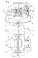
- a chassis is shown in a front view, the rail 1 comprises, which consists of flange parts 2 and a web 3 with lateral guides 3a.
- the undercarriage has two arm-shaped wheel carriers 4a, 4b, which form a frame 5a, 5b form.
- the two wheel carriers 4a, 4b are around one in the direction of the travel rail 1 axis 6 extending and running under the cross section of the rail pivoted, which allows pivoting on the rail 1, can but also be rigidly connected. It is also a combination of these two variants possible, in which the two wheel carriers 4a, 4b after Swiveling on the rail 1 are fixable.
- Fig. 1 shows that in the upper region of the wheel carrier 4a, 4b a pair opposite impellers 7 is arranged, the axes of rotation of which are horizontal run and which are supported on the wheel carriers 4a, 4b.
- One of the two Impellers 7 are driven by means of an electric motor 7a that is only operated by a motor driven, between the electric motor 7a and the driven impeller 7 a worm gear 7b is connected.
- the wheels 7 roll on the treads 8 of the lower flange.
- In front of and behind the wheels 7 are in the wheel carriers 4a, 4b each paired horizontal guide rollers 9, the lie in pairs on the web 3 of the rail 1.
- the load generates a closing moment in the wheel carriers 4a, 4b, which causes a swiveling causes the guide rollers 9 on the web 3 of the rail cross section be kept pivoted.
- the angular position between the wheel carriers 4a, 4b is limited in Figure 1 by the guide rollers 9 resting on the web 3 on both sides; the guide rollers 9 are loaded with force by the load.
- FIG. 2 is a top view of the undercarriage with the travel rail according to FIG. 1 shown.
- the only motor-operated electric motor 7a is a permanently excited one DC motor 7c; here is a low-cost collector motor Permanent magnets are provided.
- the electric motor 7a gives during its operation always a motor torque M, since it is connected to the self-locking worm gear 7b is operated with a base load torque.
- the combination of the DC motor 7a and the self-locking Worm gear 7b consequently corresponds to a drive "with the brake switched on”.
- a control device 11 shown schematically in FIG. 1 takes care of the Desired time course of the motor voltage applied to the electric motor 7a U.
- the control device 11 has a predeterminable lower one Current threshold ISU and an upper current threshold ISO and can the Check motor current I.
- the control device 11 has a predeterminable lower one Current threshold ISU and an upper current threshold ISO and can the Check motor current I.
- the Current threshold ISU the time t1 and when the Current threshold value ISO the time t2 detected in the control device 11 and the mean current change per unit of time is formed by means of the time difference t2-t1.
- control device 11 calculates a start-up time constant of the loaded chassis.
- the motor voltage U that is the current on the electric motor 7a applied voltage
- the control device 11 When braking, the motor voltage U, that is the current on the electric motor 7a applied voltage, reduced by the control device 11 so that the temporal change in motor voltage U divided by the stationary motor voltage U0 with a time constant (braking time constant) that is greater than that Approach time constant (corresponds to straight line 13, which is opposite to the straight line 12 runs; the amounts of the slopes of the two straight lines are identical).
- the Motor voltage change per unit of time can be, for example, with a time constant take place that is half the start-up time constant. That way ensures that the self-locking is switched on so slowly that the Do not block impellers 7.
- the motor voltage U is followed by the motor current I and thus the time delay motor torque M proportional to this
- a second embodiment provides that the electric motor 7a of the Control device 11 driven with identical square-wave voltage pulses whose time interval is changed by the control device 11 can.
- the time interval kept equidistant.
- the time intervals in such a way that the change in the mean of the Motor voltage U per unit time at any time t greater than that Approach time constant of the loaded chassis is.
- the start-up time constant is calculated from the reciprocal mean time Increase in engine torque (M), i.e. (t2-t1) / M, multiplied by that Motor torque (M0) of the stationary phase, i.e. (t2-t1) M0 / M, determined and to Braking the chassis reduces the engine torque (M) so that the current the engine torque (M) changes over time with a time constant, which is greater than the start-up time constant.
Landscapes
- Engineering & Computer Science (AREA)
- Mechanical Engineering (AREA)
- Electric Propulsion And Braking For Vehicles (AREA)
- Braking Arrangements (AREA)
- Connection Of Motors, Electrical Generators, Mechanical Devices, And The Like (AREA)
- Control And Safety Of Cranes (AREA)
- Carriers, Traveling Bodies, And Overhead Traveling Cranes (AREA)
Applications Claiming Priority (2)
| Application Number | Priority Date | Filing Date | Title |
|---|---|---|---|
| DE19816573 | 1998-04-07 | ||
| DE19816573 | 1998-04-07 |
Publications (3)
| Publication Number | Publication Date |
|---|---|
| EP0949183A2 true EP0949183A2 (fr) | 1999-10-13 |
| EP0949183A3 EP0949183A3 (fr) | 2002-11-13 |
| EP0949183B1 EP0949183B1 (fr) | 2004-01-21 |
Family
ID=7864526
Family Applications (1)
| Application Number | Title | Priority Date | Filing Date |
|---|---|---|---|
| EP99250093A Expired - Lifetime EP0949183B1 (fr) | 1998-04-07 | 1999-03-26 | Mécanisme de translation, en particulier pour appareils de levage et charges suspendues |
Country Status (5)
| Country | Link |
|---|---|
| US (1) | US6153992A (fr) |
| EP (1) | EP0949183B1 (fr) |
| JP (1) | JP2000086152A (fr) |
| KR (1) | KR19990082964A (fr) |
| DE (1) | DE59908337D1 (fr) |
Cited By (1)
| Publication number | Priority date | Publication date | Assignee | Title |
|---|---|---|---|---|
| CN107500144A (zh) * | 2017-09-22 | 2017-12-22 | 河北卓达建材研究院有限公司 | 一种用于房屋建设的四坐标桥式起重机 |
Families Citing this family (8)
| Publication number | Priority date | Publication date | Assignee | Title |
|---|---|---|---|---|
| GB2393709B (en) * | 2002-10-01 | 2005-12-21 | Guldmann V As | Worm drive for overhead crab |
| CN101618832B (zh) * | 2008-07-02 | 2013-05-15 | 哈尔滨理工大学 | 大型零件搬运装配的智能轨道系统 |
| FI126273B (fi) * | 2014-01-24 | 2016-09-15 | Konecranes Global Oy | Köysinostimen matalarakenteinen nostovaunu |
| FI126272B (fi) * | 2014-01-24 | 2016-09-15 | Konecranes Global Oy | Köysinostimen matalarakenteinen nostovaunu |
| CN107285194A (zh) * | 2017-08-24 | 2017-10-24 | 芜湖市长江起重设备制造有限公司 | 一种桥式起重机的电葫芦行走机构 |
| CN107601276A (zh) * | 2017-10-30 | 2018-01-19 | 中船澄西船舶修造有限公司 | 一种吊装滑车 |
| CN113371599B (zh) * | 2021-05-31 | 2022-06-28 | 泰安鑫诚机械科技有限公司 | 一种煤矿开采用单轨吊 |
| CN114436127B (zh) * | 2021-12-27 | 2025-07-15 | 山东东山新驿煤矿有限公司 | 一种单轨吊制动系统、方法及包含该制动系统的单轨吊 |
Citations (1)
| Publication number | Priority date | Publication date | Assignee | Title |
|---|---|---|---|---|
| DE19620150A1 (de) | 1996-04-19 | 1997-10-23 | Mannesmann Ag | Fahrwerk, insbesondere für Kettenzüge, Lastaufnahmemittel und/oder Schleppkabel |
Family Cites Families (10)
| Publication number | Priority date | Publication date | Assignee | Title |
|---|---|---|---|---|
| US3785463A (en) * | 1972-05-09 | 1974-01-15 | Reliance Electric Co | Final stopping control |
| US4342378A (en) * | 1979-12-27 | 1982-08-03 | Otis Elevator Company | Elevator door motion bench velocity |
| DE3005461A1 (de) * | 1980-02-14 | 1981-09-24 | M.A.N. Maschinenfabrik Augsburg-Nürnberg AG, 8500 Nürnberg | Regelung des oder der elektrischen fahrmotoren von hebezeugen mit ungefuehrter, an einem seil haengender last |
| JPS56149964A (en) * | 1980-04-18 | 1981-11-20 | Hitachi Ltd | Controller for elevator |
| DE58905066D1 (de) * | 1989-10-16 | 1993-09-02 | Otis Elevator Co | Steuerungsvorrichtung fuer aufzuganlage ohne geschwindigkeitsfuehler. |
| FI91058C (fi) * | 1991-03-18 | 1996-01-10 | Kci Kone Cranes Int Oy | Nosturin ohjausmenetelmä |
| DE4223561A1 (de) * | 1992-07-17 | 1994-01-20 | Siemens Ag | Zeitoptimierende Kranfahrwerks- bzw. Katzantriebssteuerung und -regelung |
| ES2133424T3 (es) * | 1994-01-28 | 1999-09-16 | Inventio Ag | Procedimiento para controlar el movimiento de puertas. |
| KR970003508B1 (ko) * | 1994-03-25 | 1997-03-18 | 한국원자력연구소 | 크레인의 진동방지를 위한 속도 제어 방법 |
| DE19617104C2 (de) * | 1996-04-19 | 1998-09-03 | Mannesmann Ag | Fahrwerk, insbesondere für Kettenzüge und/oder Schleppkabel |
-
1999
- 1999-03-26 DE DE59908337T patent/DE59908337D1/de not_active Expired - Fee Related
- 1999-03-26 EP EP99250093A patent/EP0949183B1/fr not_active Expired - Lifetime
- 1999-03-30 US US09/281,487 patent/US6153992A/en not_active Expired - Fee Related
- 1999-04-06 KR KR1019990011874A patent/KR19990082964A/ko not_active Withdrawn
- 1999-04-07 JP JP11099523A patent/JP2000086152A/ja active Pending
Patent Citations (1)
| Publication number | Priority date | Publication date | Assignee | Title |
|---|---|---|---|---|
| DE19620150A1 (de) | 1996-04-19 | 1997-10-23 | Mannesmann Ag | Fahrwerk, insbesondere für Kettenzüge, Lastaufnahmemittel und/oder Schleppkabel |
Cited By (1)
| Publication number | Priority date | Publication date | Assignee | Title |
|---|---|---|---|---|
| CN107500144A (zh) * | 2017-09-22 | 2017-12-22 | 河北卓达建材研究院有限公司 | 一种用于房屋建设的四坐标桥式起重机 |
Also Published As
| Publication number | Publication date |
|---|---|
| JP2000086152A (ja) | 2000-03-28 |
| DE59908337D1 (de) | 2004-02-26 |
| EP0949183A3 (fr) | 2002-11-13 |
| EP0949183B1 (fr) | 2004-01-21 |
| KR19990082964A (ko) | 1999-11-25 |
| US6153992A (en) | 2000-11-28 |
Similar Documents
| Publication | Publication Date | Title |
|---|---|---|
| DE4333281C2 (de) | Verfahren zur Regelung der Antriebs- und/oder Bremskraft der Räder eines Fahrzeugs auf optimalen Kraftschluß | |
| DE2425726C2 (de) | Transportsystem mit einer über Kopf verlaufenden Führungsschiene | |
| EP0234543A1 (fr) | Système à force magnétique pour le transport de charges à frottement réduit | |
| EP0120979B1 (fr) | Convoyeur sur rails | |
| EP0949183B1 (fr) | Mécanisme de translation, en particulier pour appareils de levage et charges suspendues | |
| AT519139B1 (de) | Regalbediengerät und Regallagersystem mit verbesserter Zugänglichkeit und Gewichtsverteilung | |
| DE19819993A1 (de) | Transportfahrzeug für eine Elektro-Hängebahn | |
| DE102016210030A1 (de) | Schienentransportsystem und Schienenfahrzeug für ein Schienentransportsystem | |
| EP2161236A2 (fr) | Transstockeur avec train de roulement | |
| DE2112796A1 (de) | Foerderer mit Selbstfahrwagen | |
| DE2411241B2 (de) | Bahnanlage | |
| DE202022102209U1 (de) | Eine Portalkran-Infrarot-Begrenzungsvorrichtung | |
| DE2523345A1 (de) | Aufzug | |
| DE3418866A1 (de) | Untergurt-elektrohaengebahn | |
| EP1878685B1 (fr) | Structure de porte pour un ascenseur | |
| DE102015118434A1 (de) | Verfahren zum Betreiben von mindestens zwei Hebezeugen in einem Gruppen-Betrieb und Anordnung mit mindestens zwei Hebezeugen | |
| EP0933314A2 (fr) | Chariot à canal pour entrepÔt automatisé | |
| DE3225595A1 (de) | Transportbahn | |
| DE69110628T2 (de) | Verbessertes Materialfördersystem unter Verwendung von angetriebenen Wagen auf einer Hängebahnschiene. | |
| DE7934593U1 (de) | Parkeinrichtung zum abstellen zweier fahrzeuge uebereinander | |
| DE102016210031A1 (de) | Schienenfahrzeug für ein Schienentransportsystem und Schienentransportsystem | |
| EP1878686B1 (fr) | Structure de porte pour un ascenseur | |
| EP2823915A1 (fr) | Centrage de mannequin pour une machine de coulée continu automatique sur un véhicule pour un mannequin | |
| EP3142914B1 (fr) | Dispositif de transport pour transporter des marchandises | |
| DE2232706A1 (de) | Transportvorrichtung |
Legal Events
| Date | Code | Title | Description |
|---|---|---|---|
| PUAI | Public reference made under article 153(3) epc to a published international application that has entered the european phase |
Free format text: ORIGINAL CODE: 0009012 |
|
| AK | Designated contracting states |
Kind code of ref document: A2 Designated state(s): AT BE CH CY DE DK ES FI FR GB GR IE IT LI LU MC NL PT SE |
|
| AX | Request for extension of the european patent |
Free format text: AL;LT;LV;MK;RO;SI |
|
| PUAL | Search report despatched |
Free format text: ORIGINAL CODE: 0009013 |
|
| AK | Designated contracting states |
Kind code of ref document: A3 Designated state(s): AT BE CH CY DE DK ES FI FR GB GR IE IT LI LU MC NL PT SE |
|
| AX | Request for extension of the european patent |
Free format text: AL;LT;LV;MK;RO;SI |
|
| 17P | Request for examination filed |
Effective date: 20030507 |
|
| GRAP | Despatch of communication of intention to grant a patent |
Free format text: ORIGINAL CODE: EPIDOSNIGR1 |
|
| AKX | Designation fees paid |
Designated state(s): DE ES FR GB IT |
|
| GRAS | Grant fee paid |
Free format text: ORIGINAL CODE: EPIDOSNIGR3 |
|
| GRAA | (expected) grant |
Free format text: ORIGINAL CODE: 0009210 |
|
| RAP1 | Party data changed (applicant data changed or rights of an application transferred) |
Owner name: DEMAG CRANES & COMPONENTS GMBH |
|
| AK | Designated contracting states |
Kind code of ref document: B1 Designated state(s): DE ES FR GB IT |
|
| PG25 | Lapsed in a contracting state [announced via postgrant information from national office to epo] |
Ref country code: IT Free format text: LAPSE BECAUSE OF FAILURE TO SUBMIT A TRANSLATION OF THE DESCRIPTION OR TO PAY THE FEE WITHIN THE PRE;WARNING: LAPSES OF ITALIAN PATENTS WITH EFFECTIVE DATE BEFORE 2007 MAY HAVE OCCURRED AT ANY TIME BEFORE 2007. THE CORRECT EFFECTIVE DATE MAY BE DIFFERENT FROM THE ONE RECORDED.SCRIBED TIME-LIMIT Effective date: 20040121 Ref country code: GB Free format text: LAPSE BECAUSE OF FAILURE TO SUBMIT A TRANSLATION OF THE DESCRIPTION OR TO PAY THE FEE WITHIN THE PRESCRIBED TIME-LIMIT Effective date: 20040121 Ref country code: FR Free format text: LAPSE BECAUSE OF FAILURE TO SUBMIT A TRANSLATION OF THE DESCRIPTION OR TO PAY THE FEE WITHIN THE PRESCRIBED TIME-LIMIT Effective date: 20040121 Ref country code: ES Free format text: LAPSE BECAUSE OF FAILURE TO SUBMIT A TRANSLATION OF THE DESCRIPTION OR TO PAY THE FEE WITHIN THE PRESCRIBED TIME-LIMIT Effective date: 20040121 |
|
| REG | Reference to a national code |
Ref country code: GB Ref legal event code: FG4D Free format text: NOT ENGLISH |
|
| REG | Reference to a national code |
Ref country code: IE Ref legal event code: FG4D Free format text: GERMAN |
|
| REF | Corresponds to: |
Ref document number: 59908337 Country of ref document: DE Date of ref document: 20040226 Kind code of ref document: P |
|
| GBV | Gb: ep patent (uk) treated as always having been void in accordance with gb section 77(7)/1977 [no translation filed] |
Effective date: 20040121 |
|
| REG | Reference to a national code |
Ref country code: IE Ref legal event code: FD4D |
|
| PLBE | No opposition filed within time limit |
Free format text: ORIGINAL CODE: 0009261 |
|
| STAA | Information on the status of an ep patent application or granted ep patent |
Free format text: STATUS: NO OPPOSITION FILED WITHIN TIME LIMIT |
|
| 26N | No opposition filed |
Effective date: 20041022 |
|
| EN | Fr: translation not filed | ||
| EN | Fr: translation not filed | ||
| REG | Reference to a national code |
Ref country code: FR Ref legal event code: ERR Free format text: BOPI DE PUBLICATION N: 05/03 PAGES: 237 PARTIE DU BULLETIN CONCERNEE: BREVETS EUROPEENS DONT LA TRADUCTION N'A PAS ETE REMISE A I'INPI IL Y A LIEU DE SUPPRIMER: LA MENTION DE LA NON REMISE. |
|
| PGFP | Annual fee paid to national office [announced via postgrant information from national office to epo] |
Ref country code: DE Payment date: 20060314 Year of fee payment: 8 |
|
| PG25 | Lapsed in a contracting state [announced via postgrant information from national office to epo] |
Ref country code: DE Free format text: LAPSE BECAUSE OF NON-PAYMENT OF DUE FEES Effective date: 20071002 |