EP0949391A2 - Traversée de toit - Google Patents
Traversée de toit Download PDFInfo
- Publication number
- EP0949391A2 EP0949391A2 EP99106594A EP99106594A EP0949391A2 EP 0949391 A2 EP0949391 A2 EP 0949391A2 EP 99106594 A EP99106594 A EP 99106594A EP 99106594 A EP99106594 A EP 99106594A EP 0949391 A2 EP0949391 A2 EP 0949391A2
- Authority
- EP
- European Patent Office
- Prior art keywords
- roof
- ventilation pipe
- covering plate
- roof ventilation
- fasteners
- Prior art date
- Legal status (The legal status is an assumption and is not a legal conclusion. Google has not performed a legal analysis and makes no representation as to the accuracy of the status listed.)
- Granted
Links
- 238000009423 ventilation Methods 0.000 claims abstract description 80
- 230000002093 peripheral effect Effects 0.000 claims description 18
- 239000004927 clay Substances 0.000 claims description 7
- 239000002184 metal Substances 0.000 claims description 4
- 230000000295 complement effect Effects 0.000 claims description 3
- 229910010293 ceramic material Inorganic materials 0.000 claims 1
- 239000000463 material Substances 0.000 description 6
- 239000000919 ceramic Substances 0.000 description 3
- 238000004519 manufacturing process Methods 0.000 description 3
- 239000004033 plastic Substances 0.000 description 3
- 239000011449 brick Substances 0.000 description 1
- 230000003993 interaction Effects 0.000 description 1
- 238000007789 sealing Methods 0.000 description 1
Images
Classifications
-
- E—FIXED CONSTRUCTIONS
- E04—BUILDING
- E04D—ROOF COVERINGS; SKY-LIGHTS; GUTTERS; ROOF-WORKING TOOLS
- E04D13/00—Special arrangements or devices in connection with roof coverings; Protection against birds; Roof drainage ; Sky-lights
- E04D13/14—Junctions of roof sheathings to chimneys or other parts extending above the roof
- E04D13/147—Junctions of roof sheathings to chimneys or other parts extending above the roof specially adapted for inclined roofs
- E04D13/1473—Junctions of roof sheathings to chimneys or other parts extending above the roof specially adapted for inclined roofs specially adapted to the cross-section of the parts extending above the roof
- E04D13/1476—Junctions of roof sheathings to chimneys or other parts extending above the roof specially adapted for inclined roofs specially adapted to the cross-section of the parts extending above the roof wherein the parts extending above the roof have a generally circular cross-section
Definitions
- the present invention relates to a roof leadthrough a roof ventilation pipe for attachment to a roof covering plate with a passage opening through which the Roof ventilation pipe can be passed through, above the Roof covering plate in the area of the passage opening Bearing is provided on which is located on an outer peripheral surface of the roof ventilation pipe attached support elements can support.
- the well-known roof duct has a roof covering plate on a dome with a dome-shaped top (support) and a passage opening in the apex area of the Owns doms.
- a roof ventilation pipe can pass through the roof covering plate passed through and across the roofing slab to be ordered.
- the roof ventilation pipe can by bracing the hood part and dome in its aligned Position are fixed. The tension leaves through on the outer circumferential surface of the roof ventilation pipe Carry out the attached ring nut.
- a disadvantage of the known roof duct is that the roof covering plate and the roof ventilation pipe are made of a stretchable plastic material, so that the clamping force is sufficient, the roof ventilation pipe in to fix different angles of inclination.
- the tension hood part and cathedral, for example, cannot on clay tile through-tiles or roof tiles from one other rigid material. Such through pans can only be complex and expensive with a trained Cathedral are made.
- Roof ventilation pipe and roof covering plate can only from be aligned and fixed on the outside of the roof.
- FIG. 22 38 826 Another roof duct is known from FR-A 22 38 826, where a roof ventilation pipe through the opening of the Roof covering plate is passed.
- a hood part support element
- FIG. 22 38 826 Another roof duct is known from FR-A 22 38 826, where a roof ventilation pipe through the opening of the Roof covering plate is passed.
- a hood part support element
- FIG. 22 38 826 Another roof duct is known from FR-A 22 38 826, where a roof ventilation pipe through the opening of the Roof covering plate is passed.
- a hood part support element
- FIG. 22 38 826 Another roof duct is known from FR-A 22 38 826, where a roof ventilation pipe through the opening of the Roof covering plate is passed.
- hood part support element
- FIG. 22 38 826 Another roof duct is known from FR-A 22 38 826, where a roof ventilation pipe through the opening of the Roof covering plate is passed.
- hood part support element
- FIG. 22 38 826 Another roof
- This known roof duct also has the disadvantage on being complicated and difficult on the roof too attach is.
- the snap lock can only thanks to considerable effort and technical skill be solved.
- the object of the present invention is therefore a roof bushing from roof ventilation pipe and roof covering plate to create that requires as few components as possible, detachably fixed on the roof with as little effort as possible can be built easily and especially for clay tile through pans suitable is.
- This task is carried out by a roof opening mentioned type solved at the below the roofing slab on the outer circumferential surface of the roof ventilation pipe two, partially surrounding the roof ventilation pipe, opposite arranged fasteners displaceable and pressurized against the underside of the roofing sheet are fixable.
- the roof bushing according to the invention can thereby Be attached to the roof ventilation pipe through the passage opening is inserted. Then be the fasteners on the outer peripheral surface of the Roof ventilation pipe below the roof covering plate fixed in such a way that edge areas of the roofing slab between the support elements of the roof ventilation pipe and the fasteners are pinched.
- the roof duct can be handled easily and detachably by the craftsman, which is below the roof surface during assembly stops.
- roof ventilation pipes with different Tilt angles to the roof surface on the roof covering plate be attached.
- the fasteners can the outer peripheral surface of the roof ventilation pipe partly right up to the underside of the roofing slab cover so that the roof ventilation pipe with sufficient security can be attached.
- the fasteners can one end in the radial direction protruding edge surfaces for contact with the bottom have the roofing slab.
- the edge surfaces can especially well on the underside of the roofing slab press when they are elastic.
- the detachable fastening of the roof ventilation pipe and the Fasteners with each other can preferably be by means of reach a ring nut. After attaching the fasteners on the roof ventilation pipe Ring nut pulled over the fasteners.
- the ring nut can preferably be built in two parts and around the fastener be stuck around.
- Other detachable types of fastening the fasteners include, for example a pipe clamp, a clamp with a quick release fastener or clip or hook mechanism for locking two or more parts for fastening the fasteners.
- the outer peripheral surface of the roof ventilation pipe can be profiled be designed, and an inner surface of the fasteners can be complementary to the outer peripheral surface his.
- the profiling (for example sawtooth-shaped or wave-shaped) enables positionable pre-adjustment the fasteners on the outer peripheral surface of the roof ventilation pipe.
- the fasteners could but also on the outer peripheral surface by a snap or Snap connection are held.
- the bracing of the roof covering plate between the support elements and fasteners can go even further thereby improve that the support elements from the roof ventilation pipe protrude radially outward and in the direction of Roof covering plate run angled. Towering Edge areas of the roof covering plate can be of such Support elements are encompassed. The fixation of the roof ventilation pipe in an inclined position is supported.
- the roof ventilation pipe After passing the roof ventilation pipe through the roofing slab determine the longitudinal extent of the the edge areas surrounding the passage opening have the angle of inclination of the roof ventilation pipe to the roof covering plate.
- the roof ventilation pipe can always be designed in the same way be while different roofing tiles Find use. Therefore, in a preferred embodiment the invention, the longitudinal extensions on the Tilt angle of a roof matched. The craftsman chooses depending on the angle of inclination of a roofing sheet with edge areas different longitudinal extension and leads then a uniform roof ventilation pipe through the Through opening. Two fasteners will be finally applied to the roof ventilation pipe the edge areas between fastening sections of the roof ventilation pipe and end faces of the fasteners to jam.
- the bracing of the edge areas between the fasteners and support elements can be optimized that the edge areas of the support elements of the roof ventilation pipe are graspable. This has the further advantage that the alignment of the roof ventilation pipe to the roof covering plate and thus to the sloping surface of the roof surface is given permanently.
- the roof ventilation pipe can be made from a wide variety Manufacture materials. Its production is preferred from Plastic, metal or ceramic (clay).
- the roofing slab is simply constructed because of it no elaborate cathedral needed, just the Edge areas delimiting the passage opening from the outside of the roof covering plate.
- the tension the roof covering plate with the roof ventilation pipe and the fasteners is not on a brace Restricted plastic material.
- the geometry of the roofing slab is therefore also used to manufacture the roofing slab made of a clay brick material (ceramic) or Suitable for metal.
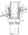
- the figure shows how a roof ventilation pipe 1 is attached a roofing plate 2 made of a clay tile material is attached.
- the roof covering plate 2 has a passage opening 3 through which the roof ventilation pipe 1 is passed through.
- the roof ventilation pipe 1 is made of a Pipe wall 4 constructed, on the outer peripheral surface 5 a Support element 6 is formed.
- the support element 6 sets consist of a part 7 and an angled part 8 together.
- the support element 6 one another embodiment could also have a pin, which engage in a groove at the end of the edge surfaces 10, 11 could. The support element 6 then closes flush with the Edge surfaces 10, 11 and forms a uniform outer wall.
- the roof covering plate 2 comprises a first and a second protruding from an outside 9 of the roofing panel 2 Edge area 10 and 11, which delimits the passage opening 3.
- the edge regions 10, 11 are delimited with the outside 9 each an angle based on the angle of inclination the roof surface is matched to the roof ventilation pipe 1 to lead vertically through the roof covering plate 2.
- the roofing plate 2 is for a roof surface with a certain inclination angle is provided at which the roof ventilation pipe 1 is aligned vertically.
- the fastening elements 13 and 14 are bowl-shaped reproduced the contour of the roof ventilation pipe 1.
- the roof ventilation pipe 1 has a length 15 or 16
- the outer peripheral surface 5 has a profile that is complementary on the inner sides 17 and 18 of the fastening elements 13 and 14 is provided.
- the profile is sawtooth-shaped formed to preposition the fasteners 13 and 14 to press on the roof ventilation pipe 1.
- the fasteners 13 and 14 can in the direction of the longitudinal axis of the roof ventilation pipe 1 on the underside 12 of the roof covering plate 2 can be pushed.
- the end faces 19 and 20 are in the radial direction outwards through edge surfaces 19a, 20a (collar) extended at the bottom 12 fit positively.
- Dimensional fluctuations in shape or geometry of the roofing plate 2 made of ceramic thereby be balanced.
- the collar can become elastic press against the bottom 12.
- ends 21 and 22 of the edge regions 10 and 11 against parts 7 of the Support elements 6 pressed.
- the support elements 6 have a Groove 23 and 24 in which the edge regions 10 and 11 of Parts 8 of the support elements 6 can be encompassed.
- the permanent fixation of the first and second fasteners 13, 14 on the roof ventilation pipe 1 achieved that the outside of the fasteners 13 and 14 have a thread on which a ring nut 25 can be raised.
- the Ring nut 25 and with the profiles 15 to 18 are the Fasteners 13 and 14 on the outer peripheral surface 5 of the roof ventilation pipe 1 fixed.
- Edge regions 10 and 11 Arranged in the direction of the roof pitch 26 Edge regions 10 and 11 also have different longitudinal extensions on how the oppositely arranged fasteners 13 and 14. The one closer to the eaves Edge region 10 has a longer extension than that Edge area facing the ridge 11. Vice versa has the fastening element 13 directed towards the eaves a smaller longitudinal extension than that facing the ridge Fastening element 14.
- a roof ventilation pipe 1 is for attachment to a roof covering plate 2 provided with a passage opening 3, through which the roof ventilation pipe 1 can be passed is.
- a support 10, 11 is provided on the itself on an outer peripheral surface 5 of the roof ventilation pipe 1 attached support elements 6 can support.
- Below the roofing plate 2 on the outer peripheral surface 5 of the Roof ventilation pipe 1 are two roof ventilation pipe 1 partially surrounding, oppositely arranged fasteners 13, 14 displaceable and under pressure against an underside 12 of the roof covering plate 2 fixable.
- the roof duct from the roof ventilation pipe 1 and roof covering plate 2 requires as few components as possible, can be solved on the roof with as little effort as possible is easy to set up and especially for Clay tile through pans suitable.
Landscapes
- Engineering & Computer Science (AREA)
- Architecture (AREA)
- Civil Engineering (AREA)
- Structural Engineering (AREA)
- Building Environments (AREA)
- Roof Covering Using Slabs Or Stiff Sheets (AREA)
- Branch Pipes, Bends, And The Like (AREA)
- Seal Device For Vehicle (AREA)
- Duct Arrangements (AREA)
Applications Claiming Priority (2)
| Application Number | Priority Date | Filing Date | Title |
|---|---|---|---|
| DE19816237 | 1998-04-11 | ||
| DE19816237A DE19816237A1 (de) | 1998-04-11 | 1998-04-11 | Dachdurchführung |
Publications (3)
| Publication Number | Publication Date |
|---|---|
| EP0949391A2 true EP0949391A2 (fr) | 1999-10-13 |
| EP0949391A3 EP0949391A3 (fr) | 2000-02-23 |
| EP0949391B1 EP0949391B1 (fr) | 2001-10-31 |
Family
ID=7864315
Family Applications (1)
| Application Number | Title | Priority Date | Filing Date |
|---|---|---|---|
| EP99106594A Expired - Lifetime EP0949391B1 (fr) | 1998-04-11 | 1999-03-31 | Traversée de toit |
Country Status (3)
| Country | Link |
|---|---|
| EP (1) | EP0949391B1 (fr) |
| AT (1) | ATE207998T1 (fr) |
| DE (2) | DE19816237A1 (fr) |
Cited By (1)
| Publication number | Priority date | Publication date | Assignee | Title |
|---|---|---|---|---|
| EP2381150A3 (fr) * | 2010-04-21 | 2013-08-07 | Robert Will | Unité d'étanchéité pour un passage de toiture ou de mur et procédé de fabrication d'un passage de toiture ou de mur |
Citations (2)
| Publication number | Priority date | Publication date | Assignee | Title |
|---|---|---|---|---|
| FR2238826A1 (en) | 1973-07-24 | 1975-02-21 | Hans Klober | Roof cover for chimney stack - comprises cylindrical pipe with convex spherical cap and locating ribs |
| DE29514513U1 (de) | 1995-09-09 | 1995-11-02 | Mage GmbH, 72250 Freudenstadt | Neigungsverstellbare Dachdurchführung |
Family Cites Families (13)
| Publication number | Priority date | Publication date | Assignee | Title |
|---|---|---|---|---|
| FR627271A (fr) * | 1927-01-08 | 1927-09-30 | Fr De L Everite Soc | Plaques de toiture en amiante-ciment |
| DE1846788U (de) * | 1961-11-04 | 1962-02-15 | August Presuhn | Entlueftungsaufsatz auf daechern. |
| FR2413616A1 (fr) * | 1977-12-29 | 1979-07-27 | Manet Claude | Lanterne d'evacuation d'air montee sur tuile a douille ou autre conduit d'extraction |
| US4437687A (en) * | 1980-11-24 | 1984-03-20 | Wilson James H | Waterproof assembly or sealing an aperture housing a conduit |
| EP0101401A3 (fr) * | 1982-08-13 | 1984-04-25 | P.C.H. Constructions Pty. Ltd. | Dispositif et procédé de raccordement étanche de toit |
| GB2132247B (en) * | 1982-12-14 | 1986-09-10 | Charles Frederick Pritchard | Roof and wall seal assemblies |
| FR2618206A1 (fr) * | 1987-07-16 | 1989-01-20 | Amphoux Andre | Adaptateur de pente de conduit. |
| DE8710071U1 (de) * | 1987-07-23 | 1987-09-10 | Schnorr, Marin, 6729 Hatzenbühl | Überdach-Entlüftungsvorrichtung |
| NL9100187A (nl) * | 1991-02-01 | 1992-09-01 | Muelink & Grol Bv | Inrichting voor de toevoer van verbrandingslucht en de afvoer van rookgassen. |
| DE9413848U1 (de) * | 1994-08-26 | 1994-10-20 | Schulte, Günter, 59757 Arnsberg | Neigungsverstellbare Dachdurchführung |
| DE19507383A1 (de) * | 1995-03-03 | 1996-09-05 | Kloeber Johannes | Dachentlüfter |
| DE19532851C1 (de) * | 1995-09-06 | 1996-10-02 | Mage Gmbh | Neigungsverstellbare Dachdurchführung |
| DE29601773U1 (de) * | 1996-02-02 | 1996-03-21 | Lück, Wilhelm, 57250 Netphen | Dachlüfter, insbesondere für geneigte Dächer, zur Dachlüftung oder zur Sanitärbelüftung von Räumen |
-
1998
- 1998-04-11 DE DE19816237A patent/DE19816237A1/de not_active Ceased
-
1999
- 1999-03-31 AT AT99106594T patent/ATE207998T1/de not_active IP Right Cessation
- 1999-03-31 DE DE59900365T patent/DE59900365D1/de not_active Expired - Fee Related
- 1999-03-31 EP EP99106594A patent/EP0949391B1/fr not_active Expired - Lifetime
Patent Citations (2)
| Publication number | Priority date | Publication date | Assignee | Title |
|---|---|---|---|---|
| FR2238826A1 (en) | 1973-07-24 | 1975-02-21 | Hans Klober | Roof cover for chimney stack - comprises cylindrical pipe with convex spherical cap and locating ribs |
| DE29514513U1 (de) | 1995-09-09 | 1995-11-02 | Mage GmbH, 72250 Freudenstadt | Neigungsverstellbare Dachdurchführung |
Cited By (1)
| Publication number | Priority date | Publication date | Assignee | Title |
|---|---|---|---|---|
| EP2381150A3 (fr) * | 2010-04-21 | 2013-08-07 | Robert Will | Unité d'étanchéité pour un passage de toiture ou de mur et procédé de fabrication d'un passage de toiture ou de mur |
Also Published As
| Publication number | Publication date |
|---|---|
| DE59900365D1 (de) | 2001-12-06 |
| EP0949391B1 (fr) | 2001-10-31 |
| DE19816237A1 (de) | 1999-10-21 |
| EP0949391A3 (fr) | 2000-02-23 |
| ATE207998T1 (de) | 2001-11-15 |
Similar Documents
| Publication | Publication Date | Title |
|---|---|---|
| DE2801902C2 (de) | Dichtungsanordnung zur Bildung einer wetterfesten Dichtung zwischen einem länglichen Bauteil und einer nicht ebenen Oberfläche | |
| DE60037585T2 (de) | Montagesystem und rückhalteclip | |
| EP0735211A1 (fr) | Goulotte d'écoulement pour toits | |
| DE69908576T2 (de) | Verbindungsvorrichtung | |
| DE9313697U1 (de) | Rinnenkörper | |
| DE19840593A1 (de) | Vorrichtung zur Herstellung einer Flachdach-Entwässerung | |
| CH673689A5 (fr) | ||
| AT248655B (de) | Flachdachabschluß | |
| EP0949391B1 (fr) | Traversée de toit | |
| EP0135698A1 (fr) | Patte de fixation de tuyau | |
| DE29818738U1 (de) | Solareindeckungsplatte | |
| DE29514513U1 (de) | Neigungsverstellbare Dachdurchführung | |
| DE69101528T2 (de) | Befestigungselement für ein Rohr, insbesondere für die Abfuhr von Regenwasser. | |
| DE4323199A1 (de) | Standkonsole für Heizkörper | |
| DE9420633U1 (de) | Verstellbarer Firstlattenhalter für eine Dachstuhlkonstruktion | |
| DE4447810C2 (de) | Deckenluftauslaß mit einem Luftanschlußkasten | |
| DE29503957U1 (de) | Klemmschelle | |
| DE19846120C1 (de) | Dachdurchführung | |
| EP0984112A1 (fr) | Dôme pour traversée de toit à inclinaison réglable | |
| DE19532851C1 (de) | Neigungsverstellbare Dachdurchführung | |
| DE102006050923B4 (de) | Schornsteinverkleidung | |
| DE4122671C1 (fr) | ||
| WO2007069051A2 (fr) | Dispositif de fixation permettant d'ajuster l'inclinaison | |
| EP0648903A1 (fr) | Panneau de couverture | |
| DE102007050451B4 (de) | Rohrstrang aus wenigstens zwei koaxialen Leitungsrohren |
Legal Events
| Date | Code | Title | Description |
|---|---|---|---|
| PUAI | Public reference made under article 153(3) epc to a published international application that has entered the european phase |
Free format text: ORIGINAL CODE: 0009012 |
|
| AK | Designated contracting states |
Kind code of ref document: A2 Designated state(s): AT BE CH DE DK ES FI FR GB GR IE IT LI LU MC NL PT SE |
|
| AX | Request for extension of the european patent |
Free format text: AL;LT;LV;MK;RO;SI |
|
| RAP1 | Party data changed (applicant data changed or rights of an application transferred) |
Owner name: HAUSPROFI BAUSYSTEME GMBH |
|
| PUAL | Search report despatched |
Free format text: ORIGINAL CODE: 0009013 |
|
| AK | Designated contracting states |
Kind code of ref document: A3 Designated state(s): AT BE CH CY DE DK ES FI FR GB GR IE IT LI LU MC NL PT SE |
|
| AX | Request for extension of the european patent |
Free format text: AL;LT;LV;MK;RO;SI |
|
| 17P | Request for examination filed |
Effective date: 20000203 |
|
| 17Q | First examination report despatched |
Effective date: 20000626 |
|
| AKX | Designation fees paid |
Free format text: AT BE CH DE DK ES FI FR GB GR IE IT LI LU MC NL PT SE |
|
| AXX | Extension fees paid |
Free format text: MK PAYMENT 20000818;SI PAYMENT 20000818 |
|
| GRAG | Despatch of communication of intention to grant |
Free format text: ORIGINAL CODE: EPIDOS AGRA |
|
| GRAG | Despatch of communication of intention to grant |
Free format text: ORIGINAL CODE: EPIDOS AGRA |
|
| GRAH | Despatch of communication of intention to grant a patent |
Free format text: ORIGINAL CODE: EPIDOS IGRA |
|
| GRAH | Despatch of communication of intention to grant a patent |
Free format text: ORIGINAL CODE: EPIDOS IGRA |
|
| GRAA | (expected) grant |
Free format text: ORIGINAL CODE: 0009210 |
|
| RIN1 | Information on inventor provided before grant (corrected) |
Inventor name: SCHUERMANN, WOLFRAM |
|
| AK | Designated contracting states |
Kind code of ref document: B1 Designated state(s): AT BE CH DE DK ES FI FR GB GR IE IT LI LU MC NL PT SE |
|
| AX | Request for extension of the european patent |
Free format text: MK PAYMENT 20000818;SI PAYMENT 20000818 |
|
| PG25 | Lapsed in a contracting state [announced via postgrant information from national office to epo] |
Ref country code: NL Free format text: LAPSE BECAUSE OF FAILURE TO SUBMIT A TRANSLATION OF THE DESCRIPTION OR TO PAY THE FEE WITHIN THE PRESCRIBED TIME-LIMIT Effective date: 20011031 Ref country code: IT Free format text: LAPSE BECAUSE OF FAILURE TO SUBMIT A TRANSLATION OF THE DESCRIPTION OR TO PAY THE FEE WITHIN THE PRE;WARNING: LAPSES OF ITALIAN PATENTS WITH EFFECTIVE DATE BEFORE 2007 MAY HAVE OCCURRED AT ANY TIME BEFORE 2007. THE CORRECT EFFECTIVE DATE MAY BE DIFFERENT FROM THE ONE RECORDED.SCRIBED TIME-LIMIT Effective date: 20011031 Ref country code: IE Free format text: LAPSE BECAUSE OF FAILURE TO SUBMIT A TRANSLATION OF THE DESCRIPTION OR TO PAY THE FEE WITHIN THE PRESCRIBED TIME-LIMIT Effective date: 20011031 Ref country code: GB Free format text: LAPSE BECAUSE OF FAILURE TO SUBMIT A TRANSLATION OF THE DESCRIPTION OR TO PAY THE FEE WITHIN THE PRESCRIBED TIME-LIMIT Effective date: 20011031 Ref country code: FR Free format text: LAPSE BECAUSE OF FAILURE TO SUBMIT A TRANSLATION OF THE DESCRIPTION OR TO PAY THE FEE WITHIN THE PRESCRIBED TIME-LIMIT Effective date: 20011031 Ref country code: FI Free format text: LAPSE BECAUSE OF FAILURE TO SUBMIT A TRANSLATION OF THE DESCRIPTION OR TO PAY THE FEE WITHIN THE PRESCRIBED TIME-LIMIT Effective date: 20011031 |
|
| REF | Corresponds to: |
Ref document number: 207998 Country of ref document: AT Date of ref document: 20011115 Kind code of ref document: T |
|
| REG | Reference to a national code |
Ref country code: CH Ref legal event code: EP |
|
| REF | Corresponds to: |
Ref document number: 59900365 Country of ref document: DE Date of ref document: 20011206 |
|
| REG | Reference to a national code |
Ref country code: IE Ref legal event code: FG4D Free format text: GERMAN |
|
| PG25 | Lapsed in a contracting state [announced via postgrant information from national office to epo] |
Ref country code: SE Free format text: LAPSE BECAUSE OF FAILURE TO SUBMIT A TRANSLATION OF THE DESCRIPTION OR TO PAY THE FEE WITHIN THE PRESCRIBED TIME-LIMIT Effective date: 20020131 Ref country code: PT Free format text: LAPSE BECAUSE OF FAILURE TO SUBMIT A TRANSLATION OF THE DESCRIPTION OR TO PAY THE FEE WITHIN THE PRESCRIBED TIME-LIMIT Effective date: 20020131 Ref country code: DK Free format text: LAPSE BECAUSE OF FAILURE TO SUBMIT A TRANSLATION OF THE DESCRIPTION OR TO PAY THE FEE WITHIN THE PRESCRIBED TIME-LIMIT Effective date: 20020131 |
|
| PG25 | Lapsed in a contracting state [announced via postgrant information from national office to epo] |
Ref country code: GR Free format text: LAPSE BECAUSE OF FAILURE TO SUBMIT A TRANSLATION OF THE DESCRIPTION OR TO PAY THE FEE WITHIN THE PRESCRIBED TIME-LIMIT Effective date: 20020201 |
|
| RAP2 | Party data changed (patent owner data changed or rights of a patent transferred) |
Owner name: SCHUERMANN, WOLFRAM |
|
| RIN2 | Information on inventor provided after grant (corrected) |
Free format text: SCHUERMANN, WOLFRAM |
|
| PG25 | Lapsed in a contracting state [announced via postgrant information from national office to epo] |
Ref country code: MC Free format text: LAPSE BECAUSE OF NON-PAYMENT OF DUE FEES Effective date: 20020331 Ref country code: LU Free format text: LAPSE BECAUSE OF NON-PAYMENT OF DUE FEES Effective date: 20020331 Ref country code: BE Free format text: LAPSE BECAUSE OF NON-PAYMENT OF DUE FEES Effective date: 20020331 Ref country code: AT Free format text: LAPSE BECAUSE OF NON-PAYMENT OF DUE FEES Effective date: 20020331 |
|
| NLV1 | Nl: lapsed or annulled due to failure to fulfill the requirements of art. 29p and 29m of the patents act | ||
| PG25 | Lapsed in a contracting state [announced via postgrant information from national office to epo] |
Ref country code: ES Free format text: LAPSE BECAUSE OF FAILURE TO SUBMIT A TRANSLATION OF THE DESCRIPTION OR TO PAY THE FEE WITHIN THE PRESCRIBED TIME-LIMIT Effective date: 20020430 |
|
| GBV | Gb: ep patent (uk) treated as always having been void in accordance with gb section 77(7)/1977 [no translation filed] |
Effective date: 20011031 |
|
| REG | Reference to a national code |
Ref country code: IE Ref legal event code: FD4D |
|
| PLBE | No opposition filed within time limit |
Free format text: ORIGINAL CODE: 0009261 |
|
| STAA | Information on the status of an ep patent application or granted ep patent |
Free format text: STATUS: NO OPPOSITION FILED WITHIN TIME LIMIT |
|
| BERE | Be: lapsed |
Owner name: *HAUSPROFI BAUSYSTEME G.M.B.H. Effective date: 20020331 |
|
| PG25 | Lapsed in a contracting state [announced via postgrant information from national office to epo] |
Ref country code: DE Free format text: LAPSE BECAUSE OF NON-PAYMENT OF DUE FEES Effective date: 20021001 |
|
| 26N | No opposition filed | ||
| PG25 | Lapsed in a contracting state [announced via postgrant information from national office to epo] |
Ref country code: LI Free format text: LAPSE BECAUSE OF NON-PAYMENT OF DUE FEES Effective date: 20030331 Ref country code: CH Free format text: LAPSE BECAUSE OF NON-PAYMENT OF DUE FEES Effective date: 20030331 |
|
| REG | Reference to a national code |
Ref country code: CH Ref legal event code: PL |