EP0949433B2 - Moteur de frein - Google Patents
Moteur de frein Download PDFInfo
- Publication number
- EP0949433B2 EP0949433B2 EP99106622A EP99106622A EP0949433B2 EP 0949433 B2 EP0949433 B2 EP 0949433B2 EP 99106622 A EP99106622 A EP 99106622A EP 99106622 A EP99106622 A EP 99106622A EP 0949433 B2 EP0949433 B2 EP 0949433B2
- Authority
- EP
- European Patent Office
- Prior art keywords
- actuating member
- brake actuator
- actuator according
- brake
- application lever
- Prior art date
- Legal status (The legal status is an assumption and is not a legal conclusion. Google has not performed a legal analysis and makes no representation as to the accuracy of the status listed.)
- Expired - Lifetime
Links
- 230000033001 locomotion Effects 0.000 claims description 33
- 238000007789 sealing Methods 0.000 claims description 17
- 230000008878 coupling Effects 0.000 claims description 9
- 238000010168 coupling process Methods 0.000 claims description 9
- 238000005859 coupling reaction Methods 0.000 claims description 9
- 230000005540 biological transmission Effects 0.000 claims description 2
- 238000013022 venting Methods 0.000 claims 1
- 238000005096 rolling process Methods 0.000 description 5
- 238000005452 bending Methods 0.000 description 4
- 230000000694 effects Effects 0.000 description 3
- 238000006073 displacement reaction Methods 0.000 description 2
- 238000004519 manufacturing process Methods 0.000 description 2
- 150000001875 compounds Chemical class 0.000 description 1
- 238000003780 insertion Methods 0.000 description 1
- 230000037431 insertion Effects 0.000 description 1
- 238000012986 modification Methods 0.000 description 1
- 230000004048 modification Effects 0.000 description 1
- 230000008092 positive effect Effects 0.000 description 1
- 230000006641 stabilisation Effects 0.000 description 1
- 238000011105 stabilization Methods 0.000 description 1
- 238000009423 ventilation Methods 0.000 description 1
Images




Classifications
-
- F—MECHANICAL ENGINEERING; LIGHTING; HEATING; WEAPONS; BLASTING
- F16—ENGINEERING ELEMENTS AND UNITS; GENERAL MEASURES FOR PRODUCING AND MAINTAINING EFFECTIVE FUNCTIONING OF MACHINES OR INSTALLATIONS; THERMAL INSULATION IN GENERAL
- F16D—COUPLINGS FOR TRANSMITTING ROTATION; CLUTCHES; BRAKES
- F16D65/00—Parts or details
- F16D65/14—Actuating mechanisms for brakes; Means for initiating operation at a predetermined position
- F16D65/16—Actuating mechanisms for brakes; Means for initiating operation at a predetermined position arranged in or on the brake
- F16D65/18—Actuating mechanisms for brakes; Means for initiating operation at a predetermined position arranged in or on the brake adapted for drawing members together, e.g. for disc brakes
-
- F—MECHANICAL ENGINEERING; LIGHTING; HEATING; WEAPONS; BLASTING
- F16—ENGINEERING ELEMENTS AND UNITS; GENERAL MEASURES FOR PRODUCING AND MAINTAINING EFFECTIVE FUNCTIONING OF MACHINES OR INSTALLATIONS; THERMAL INSULATION IN GENERAL
- F16D—COUPLINGS FOR TRANSMITTING ROTATION; CLUTCHES; BRAKES
- F16D2121/00—Type of actuator operation force
- F16D2121/14—Mechanical
-
- F—MECHANICAL ENGINEERING; LIGHTING; HEATING; WEAPONS; BLASTING
- F16—ENGINEERING ELEMENTS AND UNITS; GENERAL MEASURES FOR PRODUCING AND MAINTAINING EFFECTIVE FUNCTIONING OF MACHINES OR INSTALLATIONS; THERMAL INSULATION IN GENERAL
- F16D—COUPLINGS FOR TRANSMITTING ROTATION; CLUTCHES; BRAKES
- F16D2121/00—Type of actuator operation force
- F16D2121/18—Electric or magnetic
-
- F—MECHANICAL ENGINEERING; LIGHTING; HEATING; WEAPONS; BLASTING
- F16—ENGINEERING ELEMENTS AND UNITS; GENERAL MEASURES FOR PRODUCING AND MAINTAINING EFFECTIVE FUNCTIONING OF MACHINES OR INSTALLATIONS; THERMAL INSULATION IN GENERAL
- F16D—COUPLINGS FOR TRANSMITTING ROTATION; CLUTCHES; BRAKES
- F16D2125/00—Components of actuators
- F16D2125/18—Mechanical mechanisms
- F16D2125/20—Mechanical mechanisms converting rotation to linear movement or vice versa
- F16D2125/22—Mechanical mechanisms converting rotation to linear movement or vice versa acting transversely to the axis of rotation
- F16D2125/28—Cams; Levers with cams
- F16D2125/32—Cams; Levers with cams acting on one cam follower
Definitions
- the invention relates to a brake application device with a Zuspannhebel pivotable for applying the brake and a for applying the brake translationally movable actuator having actuator, wherein the actuator is coupled to the power transmission in terms of a brake application to the free end of the Zuspannhebels.
- Such brake application devices are known, for example from the DE 195 15 019 A1 , of the DE 43 14 720 A1 and the DE 195 18 513 A1 .
- the actuator is in each case coupled to the free end of the Zuspannhebels by means of a Kalottenlagerung, a Kugelpfannenlagerung or a hinged connection, which is why the actuator must follow the arcuate path of the free end of the Zuspannhebels during application, resulting in a pendulum movement inevitably Axis of the translational movement of the actuator results.
- the actuator must therefore be kept or guided in the known Zuspannvortechnischen in a manner that allows such a pendulum motion.
- Such Walkerrungen or guides are complex and complicated.
- it is, for example, relatively complicated and complicated to insert the actuator in the calotte.
- a generic brake application device is from the US 3895695 A wherein an actuating member for transmitting power to the brake is coupled to a brake lever that permits movement of the brake lever over the actuator in a direction transverse to the direction of translation of the actuator. Due to the fact that the application lever but abuts obliquely on the Betjanristsglied, undesirable bending moments arise on the Betat Trentsglied.
- the invention has the object of developing this brake application device, wherein the holder and guide of the actuator can be simplified and the manufacture of the coupling between the actuator and the free end of the brake lever is simplified.
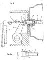
- the coupling has a perpendicular to the direction of translational movement of the actuator extending path on the actuator and a convex contour at the free end of the application lever.
- the invention is preferred suggest that a convex contour can move along a path so that the actuator is not forced to oscillate.
- the coupling of the actuator to the free end of the application lever permits movement of the free end of the application lever with respect to the actuator in a direction transverse to the direction of translational movement of the actuator.
- the actuator Since the free end of the Zuspannhebels with respect to the actuator can move in a direction transverse to the translational movement of the actuator direction, the actuator must no longer follow the arcuate path of the free end of the Zuspannhebels at Zuinstant, which is why it can no longer perform pendulum motion got to. As a result, the holder and guide of the actuator can be considerably simplified.
- the direction of the allowed by the coupling movement of the free end of the application lever with respect to the actuating member in the pivoting plane of the Zuspannhebels achieves a further simplification.
- the web is formed by a flat surface.
- each provide a coaxial bearing 15, which serve for guiding and supporting the actuator 6 on its way along the axis B.
- the inner contour of the bearing 15 corresponds to the outer contour of the actuating member 6.
- the bearing 15 is mounted either in a through hole of the housing of the actuator 3 or the brake housing 2. With the storage 15 an exact guidance or positioning of the actuator 6 is achieved. In addition, bending moments can also be absorbed by the bearing 15.
Landscapes
- Engineering & Computer Science (AREA)
- General Engineering & Computer Science (AREA)
- Mechanical Engineering (AREA)
- Braking Arrangements (AREA)
Claims (15)
- Dispositif de moteur de frein avec
un levier de moteur (5) pivotant pour le moteur du frein et
un dispositif d'actionnement (3) comportant un organe d'actionnement (6) mobile en translation pour le moteur du frein,
dans lequel l'organe d'actionnement (6) est couplé avec le levier de moteur (5) pour la transmission de force dans le sens d'un moteur du frein, dans lequel
le couplage de l'organe d'actionnement (6) avec le levier de moteur (5) permet un déplacement de l'extrémité libre du levier de moteur (5) par rapport à l'organe d'actionnement (6) dans une direction perpendiculaire à la direction (B) du mouvement de translation de l'organe d'actionnement (6),
caractérisé en ce que
l'organe d'actionnement est couplé avec l'extrémité libre du levier de moteur (5) et
le couplage comporte une glissière (7; 12) s'étendant perpendiculairement à la direction (B) du mouvement de translation de l'organe d'actionnement (6) sur l'organe d'actionnement (6) et un profil convexe (8 ; 9 ; 11) sur l'extrémité libre du levier de moteur (5). - Dispositif de moteur de frein selon la revendication 1, caractérisé en ce que la direction (A) du déplacement de l'extrémité libre du levier de moteur (5) permise par le couplage par rapport à l'organe d'actionnement (6), se trouve dans le plan de pivotement du levier de moteur (5).
- Dispositif de moteur de frein selon la revendication 1 ou 2, caractérisé en ce que la glissière (7) est formée par une surface plane.
- Dispositif de moteur de frein selon la revendication 3, caractérisé en ce que le profil convexe est formé par la surface d'une bille (11) et la glissière (12) présente un profil concave dont la section transversale correspond à l'enveloppe de la bille.
- Dispositif de moteur de frein selon l'une quelconque des revendications précédentes, caractérisé en ce que la glissière (7; 12) se trouve à l'intérieur d'une gorge dont les parois (10) servent au guidage latéral lors du déplacement relatif entre l'extrémité libre du levier de moteur (5) et l'organe d'actionnement (6).
- Dispositif de moteur de frein selon l'une quelconque des revendications précédentes, caractérisé en ce que le profil convexe est formé par la surface d'une bille (11), d'un rouleau (9) ou d'un palier à roulement (9.1) qui est maintenu(e) de telle manière qu'elle/il roule sur la glissière (7; 12) lors du déplacement relatif entre l'extrémité libre du levier de moteur (5) et l'organe d'actionnement (6).
- Dispositif de moteur de frein selon l'une quelconque des revendications 1 à 3 et 5, caractérisé en ce que la glissière est formée par une paroi longitudinale d'un trou oblong (13), le trou oblong (13) entourant un rouleau (9) servant de profil convexe ou un palier à roulement (9.1) servant de profil convexe le long de la direction s'étendant perpendiculairement à la direction du mouvement de translation de l'organe d'actionnement.
- Dispositif de moteur de frein selon la revendication 7, caractérisé par une ouverture (14) dans la paroi périphérique du trou oblong (13) pour l'insertion du rouleau (9) ou du palier à roulement (9.1).
- Dispositif de moteur de frein selon l'une quelconque des revendications précédentes, caractérisé par au moins un palier (15) pour le support et le guidage de l'organe d'actionnement (6) lors mouvement de translation.
- Dispositif de moteur de frein selon la revendication 9, caractérisé en ce que le levier de moteur (5) est disposé dans un boîtier de frein (2) avec une ouverture de passage pour l'organe d'actionnement (6), un premier palier (15) étant disposé dans la zone de l'ouverture de passage dans le boîtier de frein (2).
- Dispositif de moteur de frein selon la revendication 9 ou 10, caractérisé par au moins un dispositif d'étanchéité (16) entre le premier palier (15) et l'organe d'actionnement (6).
- Dispositif de moteur de frein selon la revendication 11, caractérisé par au moins deux dispositifs d'étanchéité (16, 16.1) disposés l'un derrière l'autre dans la direction (B) du mouvement de translation entre le premier palier (15) et l'organe d'actionnement (6).
- Dispositif de moteur de frein selon la revendication 12, caractérisé par un dispositif de ventilation (19) entre les deux dispositifs d'étanchéité (16, 16.1) qui relie l'intérieur du premier palier avec l'environnement extérieur.
- Dispositif de moteur de frein selon l'une quelconque des revendications 9 à 13, caractérisé en ce que le dispositif d'actionnement (3) comporte un boîtier (21) avec une ouverture de passage pour l'organe d'actionnement (6), un deuxième palier (20) étant disposé dans la zone de l'ouverture de passage dans le boîtier (21).
- Dispositif de moteur de frein selon la revendication 14, caractérisé en ce que le deuxième palier (20) comporte un piston (22) guidé de manière étanche dans l'ouverture de passage du boîtier (21) du dispositif d'actionnement (3).
Applications Claiming Priority (2)
| Application Number | Priority Date | Filing Date | Title |
|---|---|---|---|
| DE19815406 | 1998-04-06 | ||
| DE1998115406 DE19815406A1 (de) | 1998-04-06 | 1998-04-06 | Bremsenzuspannvorrichtung |
Publications (4)
| Publication Number | Publication Date |
|---|---|
| EP0949433A2 EP0949433A2 (fr) | 1999-10-13 |
| EP0949433A3 EP0949433A3 (fr) | 2001-01-31 |
| EP0949433B1 EP0949433B1 (fr) | 2006-06-07 |
| EP0949433B2 true EP0949433B2 (fr) | 2011-06-15 |
Family
ID=7863777
Family Applications (1)
| Application Number | Title | Priority Date | Filing Date |
|---|---|---|---|
| EP99106622A Expired - Lifetime EP0949433B2 (fr) | 1998-04-06 | 1999-03-31 | Moteur de frein |
Country Status (2)
| Country | Link |
|---|---|
| EP (1) | EP0949433B2 (fr) |
| DE (2) | DE19815406A1 (fr) |
Families Citing this family (9)
| Publication number | Priority date | Publication date | Assignee | Title |
|---|---|---|---|---|
| DE10021571B4 (de) * | 2000-05-03 | 2010-04-29 | Knorr-Bremse Systeme für Nutzfahrzeuge GmbH | Druckluftbetätigte Scheibenbremse mit Druckelementen |
| DE10109305A1 (de) * | 2001-02-26 | 2002-09-05 | Daimler Chrysler Ag | Elektromechanische Fahrzeugbremse |
| DE102006033254B3 (de) * | 2006-07-18 | 2007-09-13 | Wabco Radbremsen Gmbh | Scheibenbremse, insbesondere für Nutzfahrzeuge, sowie Betätigungszylinder einer solchen Scheibenbremse |
| DE102006050522B4 (de) * | 2006-10-26 | 2008-09-18 | Knorr-Bremse Systeme für Nutzfahrzeuge GmbH | Zuspannvorrichtung für eine mechanisch betätigbare Scheibenbremse |
| DE102006056710A1 (de) * | 2006-11-30 | 2008-06-05 | Wabco Gmbh | Druckluftbremszylinder in Kolbenbauweise |
| GB2455986B (en) | 2007-12-24 | 2011-12-07 | Meritor Heavy Vehicle Braking | Retaining formation |
| DE102014111546B4 (de) * | 2014-08-13 | 2021-06-17 | Knorr-Bremse Systeme für Nutzfahrzeuge GmbH | Zuspannvorrichtung für eine drehhebelbetätigte Scheibenbremse |
| DE102018117574A1 (de) * | 2018-07-20 | 2020-01-23 | Knorr-Bremse Systeme für Nutzfahrzeuge GmbH | Scheibenbremse mit einem elektrischen Aktuator und Verfahren zum Einstellen eines definierten Lüftspiels einer Scheibenbremse |
| GB2644064A (en) * | 2024-09-13 | 2026-03-18 | Meritor Heavy Vehicle Braking Systems Uk Ltd | Actuator for a heavy vehicle foundation brake |
Citations (3)
| Publication number | Priority date | Publication date | Assignee | Title |
|---|---|---|---|---|
| US2375392A (en) † | 1943-01-16 | 1945-05-08 | Stelzer William | Brake |
| DE19515019A1 (de) † | 1995-04-24 | 1996-10-31 | Perrot Bremsen Gmbh | Scheibenbremse |
| DE19518513A1 (de) † | 1995-05-19 | 1996-11-21 | Knorr Bremse Systeme | Bremszuspannvorrichtung |
Family Cites Families (4)
| Publication number | Priority date | Publication date | Assignee | Title |
|---|---|---|---|---|
| US3324771A (en) * | 1965-04-23 | 1967-06-13 | Wagner Electric Corp | Friction device operating mechanism |
| GB1458391A (en) * | 1973-02-24 | 1976-12-15 | Davies Metcalfe Ltd | Spring brake unit |
| US3967705A (en) * | 1975-04-02 | 1976-07-06 | The Bendix Corporation | Application adjuster for disc brake |
| DE4314720A1 (de) | 1993-05-04 | 1994-11-10 | Knorr Bremse Ag | Druckluftbetätigte Scheibenbremse |
-
1998
- 1998-04-06 DE DE1998115406 patent/DE19815406A1/de not_active Withdrawn
-
1999
- 1999-03-31 EP EP99106622A patent/EP0949433B2/fr not_active Expired - Lifetime
- 1999-03-31 DE DE59913499T patent/DE59913499D1/de not_active Expired - Lifetime
Patent Citations (3)
| Publication number | Priority date | Publication date | Assignee | Title |
|---|---|---|---|---|
| US2375392A (en) † | 1943-01-16 | 1945-05-08 | Stelzer William | Brake |
| DE19515019A1 (de) † | 1995-04-24 | 1996-10-31 | Perrot Bremsen Gmbh | Scheibenbremse |
| DE19518513A1 (de) † | 1995-05-19 | 1996-11-21 | Knorr Bremse Systeme | Bremszuspannvorrichtung |
Also Published As
| Publication number | Publication date |
|---|---|
| EP0949433A3 (fr) | 2001-01-31 |
| DE19815406A1 (de) | 1999-10-07 |
| DE59913499D1 (de) | 2006-07-20 |
| EP0949433A2 (fr) | 1999-10-13 |
| EP0949433B1 (fr) | 2006-06-07 |
Similar Documents
| Publication | Publication Date | Title |
|---|---|---|
| DE4308679B4 (de) | Ventil | |
| WO1996026343A1 (fr) | Ferme-porte | |
| DE2707657C2 (de) | Durchbiegungseinstellwalze | |
| EP0949433B2 (fr) | Moteur de frein | |
| WO2011091451A1 (fr) | Dispositif pour fermer une ouverture dans une paroi de chambre | |
| EP2100023A1 (fr) | Dispositif de commande de soupape | |
| EP0020862A1 (fr) | Dispositif de ventilation d'un frein de service et d'un frein à ressort combinés | |
| DE212018000381U1 (de) | Werkzeug-Klemmvorrichtung für eine Werkzeugmaschine und Werkzeugmaschine | |
| WO2024188559A1 (fr) | Dispositif de serrage et/ou de freinage pneumatique | |
| EP0025559A1 (fr) | Dispositif de ventilation d'un cylindre de frein à ressort, plus particulièrement d'un cylindre de frein de service et à ressort combinés | |
| DE102007024787B4 (de) | Kraftübertragungseinrichtung für Fahrzeugbremsen | |
| EP2427669B1 (fr) | Frein de stationnement d'un véhicule sur rails ayant un rendement élevé | |
| DE3414821C2 (de) | Dichtungsanordnung | |
| DE69005712T2 (de) | Aufhängungselement für Kraftfahrzeuge. | |
| EP3171063A1 (fr) | Vanne d'angle à vide à commande à coulisse | |
| EP1136337B1 (fr) | Cylindre combiné de frein de service et à ressort | |
| EP4474103B1 (fr) | Dispositif de serrage et/ou de freinage pour environnements humides | |
| EP1284171A1 (fr) | Dispositif de fixation pour une unité de mouvement linéaire | |
| DE20013052U1 (de) | Handbetätigungseinrichtung für Ventile | |
| EP4431229B1 (fr) | Dispositif pneumatique de serrage et/ou de freinage | |
| DE60129161T2 (de) | Bremskraftverstärker mit einen hohen schwellwert aufweisendem sicherheitsventil | |
| DE10305593A1 (de) | Drehdurchführung zur Versorgung eines Rotors einer bedruckstoffverarbeitenden Maschine mit einem Arbeitsfluid | |
| DE69810078T2 (de) | Verfahren zur beaufschlagung der dichtungsleiste einer saugwalze und dichtungsleiste für eine walze | |
| DE10038734A1 (de) | Gedämpfter Pneumatikzylinder zur Erzeugung einer konstanten langsamen linearen Antriebsbewegung | |
| EP2738332B1 (fr) | Actionnement de porte |
Legal Events
| Date | Code | Title | Description |
|---|---|---|---|
| PUAI | Public reference made under article 153(3) epc to a published international application that has entered the european phase |
Free format text: ORIGINAL CODE: 0009012 |
|
| AK | Designated contracting states |
Kind code of ref document: A2 Designated state(s): DE GB SE |
|
| AX | Request for extension of the european patent |
Free format text: AL;LT;LV;MK;RO;SI |
|
| RIN1 | Information on inventor provided before grant (corrected) |
Inventor name: FALTER, WOLFGANG DIPL.-ING. Inventor name: ANTONY, PAUL DIPL.-ING. Inventor name: MACKE, WLODZIMIERZ DIPL.-ING. |
|
| PUAL | Search report despatched |
Free format text: ORIGINAL CODE: 0009013 |
|
| AK | Designated contracting states |
Kind code of ref document: A3 Designated state(s): AT BE CH CY DE DK ES FI FR GB GR IE IT LI LU MC NL PT SE |
|
| AX | Request for extension of the european patent |
Free format text: AL;LT;LV;MK;RO;SI |
|
| 17P | Request for examination filed |
Effective date: 20010726 |
|
| AKX | Designation fees paid |
Free format text: DE GB SE |
|
| 17Q | First examination report despatched |
Effective date: 20050504 |
|
| GRAP | Despatch of communication of intention to grant a patent |
Free format text: ORIGINAL CODE: EPIDOSNIGR1 |
|
| RIC1 | Information provided on ipc code assigned before grant |
Ipc: 7F 16D 65/14 B Ipc: 7F 16D 65/16 A |
|
| GRAS | Grant fee paid |
Free format text: ORIGINAL CODE: EPIDOSNIGR3 |
|
| GRAA | (expected) grant |
Free format text: ORIGINAL CODE: 0009210 |
|
| AK | Designated contracting states |
Kind code of ref document: B1 Designated state(s): DE GB SE |
|
| REG | Reference to a national code |
Ref country code: GB Ref legal event code: FG4D Free format text: NOT ENGLISH |
|
| REF | Corresponds to: |
Ref document number: 59913499 Country of ref document: DE Date of ref document: 20060720 Kind code of ref document: P |
|
| GBT | Gb: translation of ep patent filed (gb section 77(6)(a)/1977) |
Effective date: 20060703 |
|
| REG | Reference to a national code |
Ref country code: SE Ref legal event code: TRGR |
|
| PLBI | Opposition filed |
Free format text: ORIGINAL CODE: 0009260 |
|
| PLAX | Notice of opposition and request to file observation + time limit sent |
Free format text: ORIGINAL CODE: EPIDOSNOBS2 |
|
| 26 | Opposition filed |
Opponent name: KNORR-BREMSE SYSTEME FUER NUTZFAHRZEUGE GMBH Effective date: 20070306 |
|
| PLBB | Reply of patent proprietor to notice(s) of opposition received |
Free format text: ORIGINAL CODE: EPIDOSNOBS3 |
|
| PLAB | Opposition data, opponent's data or that of the opponent's representative modified |
Free format text: ORIGINAL CODE: 0009299OPPO |
|
| RAP2 | Party data changed (patent owner data changed or rights of a patent transferred) |
Owner name: WABCO RADBREMSEN GMBH |
|
| APBM | Appeal reference recorded |
Free format text: ORIGINAL CODE: EPIDOSNREFNO |
|
| APBP | Date of receipt of notice of appeal recorded |
Free format text: ORIGINAL CODE: EPIDOSNNOA2O |
|
| APAH | Appeal reference modified |
Free format text: ORIGINAL CODE: EPIDOSCREFNO |
|
| APBQ | Date of receipt of statement of grounds of appeal recorded |
Free format text: ORIGINAL CODE: EPIDOSNNOA3O |
|
| APBU | Appeal procedure closed |
Free format text: ORIGINAL CODE: EPIDOSNNOA9O |
|
| PUAH | Patent maintained in amended form |
Free format text: ORIGINAL CODE: 0009272 |
|
| STAA | Information on the status of an ep patent application or granted ep patent |
Free format text: STATUS: PATENT MAINTAINED AS AMENDED |
|
| 27A | Patent maintained in amended form |
Effective date: 20110615 |
|
| AK | Designated contracting states |
Kind code of ref document: B2 Designated state(s): DE GB SE |
|
| REG | Reference to a national code |
Ref country code: DE Ref legal event code: R102 Ref document number: 59913499 Country of ref document: DE Effective date: 20110615 |
|
| PGFP | Annual fee paid to national office [announced via postgrant information from national office to epo] |
Ref country code: GB Payment date: 20110329 Year of fee payment: 13 |
|
| REG | Reference to a national code |
Ref country code: SE Ref legal event code: RPEO |
|
| PG25 | Lapsed in a contracting state [announced via postgrant information from national office to epo] |
Ref country code: DE Free format text: LAPSE BECAUSE OF NON-PAYMENT OF DUE FEES Effective date: 20111001 |
|
| PGFP | Annual fee paid to national office [announced via postgrant information from national office to epo] |
Ref country code: SE Payment date: 20120313 Year of fee payment: 14 |
|
| GBPC | Gb: european patent ceased through non-payment of renewal fee |
Effective date: 20120331 |
|
| PG25 | Lapsed in a contracting state [announced via postgrant information from national office to epo] |
Ref country code: GB Free format text: LAPSE BECAUSE OF NON-PAYMENT OF DUE FEES Effective date: 20120331 |
|
| REG | Reference to a national code |
Ref country code: SE Ref legal event code: EUG |
|
| PG25 | Lapsed in a contracting state [announced via postgrant information from national office to epo] |
Ref country code: SE Free format text: LAPSE BECAUSE OF NON-PAYMENT OF DUE FEES Effective date: 20130401 |
|
| REG | Reference to a national code |
Ref country code: DE Ref legal event code: R082 Ref document number: 59913499 Country of ref document: DE Representative=s name: LEINWEBER & ZIMMERMANN, DE |
|
| REG | Reference to a national code |
Ref country code: DE Ref legal event code: R082 Ref document number: 59913499 Country of ref document: DE Representative=s name: LEINWEBER & ZIMMERMANN, DE Effective date: 20140708 Ref country code: DE Ref legal event code: R081 Ref document number: 59913499 Country of ref document: DE Owner name: WABCO EUROPE BVBA, BE Free format text: FORMER OWNER: WABCO PERROT BREMSEN GMBH, 68229 MANNHEIM, DE Effective date: 20140708 |
|
| PGFP | Annual fee paid to national office [announced via postgrant information from national office to epo] |
Ref country code: DE Payment date: 20180322 Year of fee payment: 20 |
|
| REG | Reference to a national code |
Ref country code: DE Ref legal event code: R071 Ref document number: 59913499 Country of ref document: DE |