EP0949496A1 - Méthode de détermination de la condition de circulation des pneumatiques de véhicules - Google Patents
Méthode de détermination de la condition de circulation des pneumatiques de véhicules Download PDFInfo
- Publication number
- EP0949496A1 EP0949496A1 EP99201029A EP99201029A EP0949496A1 EP 0949496 A1 EP0949496 A1 EP 0949496A1 EP 99201029 A EP99201029 A EP 99201029A EP 99201029 A EP99201029 A EP 99201029A EP 0949496 A1 EP0949496 A1 EP 0949496A1
- Authority
- EP
- European Patent Office
- Prior art keywords
- tyre
- stiffness
- hub
- model
- belt
- Prior art date
- Legal status (The legal status is an assumption and is not a legal conclusion. Google has not performed a legal analysis and makes no representation as to the accuracy of the status listed.)
- Granted
Links
Images









Classifications
-
- G—PHYSICS
- G01—MEASURING; TESTING
- G01M—TESTING STATIC OR DYNAMIC BALANCE OF MACHINES OR STRUCTURES; TESTING OF STRUCTURES OR APPARATUS, NOT OTHERWISE PROVIDED FOR
- G01M17/00—Testing of vehicles
- G01M17/007—Wheeled or endless-tracked vehicles
- G01M17/02—Tyres
-
- B—PERFORMING OPERATIONS; TRANSPORTING
- B60—VEHICLES IN GENERAL
- B60C—VEHICLE TYRES; TYRE INFLATION; TYRE CHANGING; CONNECTING VALVES TO INFLATABLE ELASTIC BODIES IN GENERAL; DEVICES OR ARRANGEMENTS RELATED TO TYRES
- B60C99/00—Subject matter not provided for in other groups of this subclass
- B60C99/003—Tyre heating arrangements
-
- B—PERFORMING OPERATIONS; TRANSPORTING
- B60—VEHICLES IN GENERAL
- B60C—VEHICLE TYRES; TYRE INFLATION; TYRE CHANGING; CONNECTING VALVES TO INFLATABLE ELASTIC BODIES IN GENERAL; DEVICES OR ARRANGEMENTS RELATED TO TYRES
- B60C99/00—Subject matter not provided for in other groups of this subclass
- B60C99/006—Computer aided tyre design or simulation
-
- G—PHYSICS
- G06—COMPUTING OR CALCULATING; COUNTING
- G06F—ELECTRIC DIGITAL DATA PROCESSING
- G06F30/00—Computer-aided design [CAD]
- G06F30/10—Geometric CAD
- G06F30/15—Vehicle, aircraft or watercraft design
Definitions
- This invention relates to a method for determining the road handling of a tyre of a wheel for a vehicle.
- the object of this invention is to provide a scientific methodology with which to identify the performance characteristics of a tyre in relation to road handling, on the basis of previously defined design specifications.
- said selected physical quantities are the total drift stiffness K d of said tyre, in turn comprising the structural stiffness K c and the tread stiffness K b , and the total camber stiffness K ⁇ of said tyre.
- said method also comprises
- said degrees of freedom referred to at previous point b) are composed of:
- said selected series of virtual dynamic tests referred to at previous point f) comprises a first and a second test with said tyre blown up and not pressed to the ground, said first test consisting in imposing a translation in the transverse direction y on the hub and in measuring the lateral displacement y c of at least one selected cardinal point of said belt and the force created between said hub and said belt in order to identify said mass M c, said lateral stiffness K cy , and said lateral damping R cy , said second test consisting in imposing a camber rotation ⁇ x on said hub and in measuring the lateral displacement of at least one selected cardinal point of said belt y c and the torque transmitted between said hub and said belt in order to identify said diametral moment of inertia J c , said camber torsional stiffness K c ⁇ x , said camber torsional damping R c ⁇ x , said yawing torsional stiffness K c ⁇ z and said y
- said selected series of virtual dynamic tests referred to at previous point f) also comprises a third and a fourth test with said tyre blown up, pressed to the ground and bereft of said tread at least in said area of contact, said third test consisting in applying to said hub a sideward force in the transverse direction F y and in measuring the lateral displacement y c of said hub and of at least two selected cardinal points of said belt in order to identify said residual lateral stiffness K ry , said residual lateral damping R ry , said camber residual stiffness K r ⁇ x , and said camber residual damping R r ⁇ x , said fourth test consisting in applying to said hub a yawing torque C ⁇ z and in measuring the yaw rotation of said hub ⁇ m and the lateral displacement y c of at least one selected cardinal point of said belt in order to identify said residual yawing stiffness K r ⁇ z and said residual yawing damping R r ⁇ z .
- said method also comprises
- said method also comprises:
- said first elements of said second, finite-element model have linear form functions and their stiffness matrix is determined by means of selected static and dynamic tests conducted on specimens of said mixes, whereas the stiffness matrix of said second elements is determined by means of selected static tests on specimens of said reinforcing materials.
- the concentrated-parameter model is equivalent to a kind of dynamic concentration of the complex finite-element model, summarizing all its dynamic characteristics in a low number of mass, damping and stiffness parameters.
- the method enables identification of the structural parameters needed for the complete description of the first physical model using simulated virtual numerical tests with a second, extremely detailed model built from finite element models (F.E.M.) reproducing the behaviour of the non-rolling tyre (not drifting).
- F.E.M. finite element models
- One of the major advantages of the method according to the invention is that it partly dispenses with the need to construct physical prototypes and the resultant experimental tests in the iterative process of tyre determination, replacing this approach with virtual prototyping.
- the tyre's design parameters (characteristics of the mixes, inclination of the threads, shape of the sidewalls, width of the belt, etc.) are directly fed into the second, finite-element model which is extremely detailed.
- the concentrated parameters of the first physical model are identified by minimizing the difference between the vibrational dynamic behaviour of the second, finite-element model of the non-rolling tyre and the corresponding response given by the first physical model.
- the identification procedure defined comprises various operations that are executed in a precise, pre-established order. Starting from the transfer functions obtained by means of a series of virtual dynamic tests conducted on the non-rolling finite-element model, the masses, stiffnesses and dampings of the concentrated-parameter model are determined, providing a better description of the dynamic behaviour of the tyre.
- the identification procedure enables a link to be established between the design parameters (fed into the second finite-element model) and the condensed structural properties (contained in the first model with nine degrees of freedom), which is extremely useful in the construction of a tyre.
- the method consists in linking the design parameters of the tyre, characteristics such as the mixture and the belt, to the structural parameters, for instance the structural stiffness and camber stiffness of the tyre, because the quantities appearing in the model used have a physical significance.
- these quantities are directly linked to the design parameters, in other words the model used is a physical model.
- the model permits identification of the structural parameters starting from dynamic analysis made on the second, finite-element model of the non-rolling tyre.
- One requirement of the concentrated-parameter model is, in fact, that it be predictive of actual behaviour of the tyre.
- One of the main advantages of the method according to the invention is that the concentrated parameters are not identified by means of experimental tests on prototypes, but by means of virtual dynamic tests on the finite-element model of the non-rolling tyre.
- the method according to the invention uses a model of contact between tyre and road that enables forecasting of the drift curves at steady state. Also fed into the brush model, in addition to the longitudinal and transversal stiffness of the inserts of the tread, was their torsional stiffness, these stiffnesses being identified by means of numerical simulations on the second finite-element model, without any need for experimental tests.
- the method according to the invention enables drift curves to be determined
- the method according to the invention also enables transient state drift behaviour of the tyre to be evaluated, making allowance in the brush model for the dynamic deformations undergone by the inserts of the tread in this stage.
- Illustrated in fig. 1 is a concentrated-parameter physical model, indicated generically with the numeral 1, reproducing the drift behaviour of a tyre of a wheel, made from selected mixes of rubber and reinforcing materials.
- the physical model 1 comprises a rigid ring 2 which represents a tread band provided with inserts, a belting structure and corresponding carcass portion of the tyre, and a rigid disk 3 representing a hub of the wheel and beading of the tyre.
- the model 1 also comprises principal springs 4, 5 and 6 and principal dampers 7, 8 and 9 which connect the rigid ring 2 to the hub 3 and represent sidewalls of the tyre and air under pressure inside the tyre.
- the model also comprises supplementary springs 10, 11 and 12 and supplementary dampers 13, 14 and 15 which represent phenomena of deformation of the belt through the effect of a specified vertical load.
- the brush model 20 Associated with the physical model 1 is a brush model 20 which simulates physical phenomena present in an area of contact between tyre and road.
- the brush model 20 comprises a rigid plate 21 under which a system representing the tread is applied.
- the system is preferably bidimensional and comprises numerous parallel, deformable beams 22 orientated longitudinally, the ends of which are hinged to the plate, and numerous microinserts, or rows of springs, 23 arranged in parallel.
- the bottom ends of the microinserts 23 of the brush model interact with a road or the ground 24.
- the model reproduces the local deformations occurring inside the area of contact and represents the uniformly distributed lateral and torsional stiffnesses of the portion of tread in the area of contact.
- the rigid ring 2 has an equivalent roll radius r [m], mass M c [kg] and diametral moment of inertia J c [kg*m 2 ].
- the rigid disk 3 has mass M m [kg] and diametral moment of inertia J m [kg*m 2 ].
- the principal springs 4, 5 and 6 have structural stiffnesses K c , respectively comprising lateral stiffness K cy [N/m] between hub and belt, camber torsional stiffness K c ⁇ x [Nm/rad] between hub and belt and yawing torsional stiffness K c ⁇ z [Nm/rad] between hub and belt.
- the principal dampers 7, 8 and 9 have structural dampings R c , respectively comprising lateral damping R cy [Ns/m] between hub and belt, camber torsional damping R c ⁇ x [Nms/rad] between hub and belt and yawing torsional damping R c ⁇ z [Nms/rad] between hub and belt.
- the supplementary springs 10, 11 and 12 have residual stiffnesses K r , respectively comprising residual lateral stiffness K ry [N/m], residual camber torsional stiffness K r ⁇ x [Nm/rad] and residual yawing torsional stiffness K r ⁇ z [Nm/rad].
- the supplementary dampers 13, 14 and 15 have residual dampings R r , respectively comprising residual lateral damping R ry [Ns/m], residual camber torsional damping R r ⁇ x [Nms/rad] and residual yawing torsional damping R r ⁇ z [Nms/rad].
- the residual stiffnesses and dampings permit allowance to be made for the variation of local stiffness due to deflection of the tyre.
- the lateral and residual yawing stiffnesses K ry and K r ⁇ x connect the bottom end of the rigid ring to the plate, as also does the residual camber stiffness K r ⁇ z .
- the camber deformation of the plate ⁇ b absolute rolling rotation
- the stiffness K r ⁇ x already incorporates the effect due to camber deformability of the brush model.
- the equivalent system has stiffness per unit length c py and the contact area has a dynamic length 2a and dynamic width 2b.
- Shown in fig. 1 is an absolute trio of reference axes O-X-Y-Z having versors i, j, k, where the origin O coincides with the centre of the hub with the tyre non-deformed, the X axis lies in the plane of the hub and is of longitudinal direction, the Y axis is perpendicular to the X axis and the Z axis is vertical.
- the degrees of freedom of the physical model 1 are:
- a further degree of freedom is:
- Motion of the physical model is described by assuming small displacements and small rotations of the hub.
- the tyre is described using a Finite-Element Model (F.E.M.) 30 depicted in fig. 2.
- the finite-element model 30 comprises first elements (bricks or shells or multilayer composites) with a selected number of nodes, having appropriately selected form functions, preferably of the first or second order and, even more preferably, linear, and second elements suitable for describing the reinforcing materials.
- Each first element has a first stiffness matrix which is determined using a selected characterization of the mixes and a second supplementary stiffness matrix which is determined using a selected characterization of the reinforcing materials.
- the static tests consist of tensile, compression and shear tests in which the test conditions, forces and elongations applied are established in relation to the properties of the mixes measured previously (hardness, etc.).
- the Mooney-Rivlin law of hyperelasticity was taken as the constitutive law. This law describes the specific deformation energy in relation to the derivatives of the displacements (deformations), separating the form variation energy from the volume variation energy (deviatoric and hydrostatic part of the stress tensor).
- the coefficients of the constitutive law are calculated in such a way as to minimize the difference between the experimental and the calculated deformation energy.
- the dynamic tests are conducted by applying first a static predeformation to the specimens and then an oscillating load with frequency in the range from 0.1 to 100 Hz.
- the dynamic modulus of the mixture is thus detected as the complex ratio between stress and deformation.
- the modulus and relative phase between stress and deformation are measured.
- the reinforcing materials used are fabrics and of metallic type.
- metallic cords are used only for the belts and fabric cords for the carcass and the outermost belt (zero degrees) located just under the tread band.
- the metallic cord is subjected to pulling until it breaks and to compression in order to obtain by experimental means the characteristic of the cord from critical load to breaking. This characteristic is implemented in the finite-element model.
- the fabric cord is also subjected to pulling until it breaks.
- the second elements that describe the reinforcing materials are defined within the first elements (bricks, for instance) of the finite-element model 30, by assigning the geometrical disposition of the fabrics, the orientation of the cord, the spacing between the single cords (thickness) and the experimentally obtained traction and compression characteristic of the cord. These characteristics, in relation to the dimensions of the brick element taken, are resumed in a supplementary stiffness matrix which is overlaid on the mixture stiffness matrix, enabling extraction of the cord tensions.
- a frequency domain analysis is performed, wherein a linearized response is determined to a harmonic excitation based on the single degrees of freedom of the physical model.
- the response is obtained by resolving a matrix system, complete with mass, damping and stiffness matrices. Linearization of the matrices is performed at the end of the preliminary static determination stages so that non-linear behaviour of the actual tyre is implicitly taken into account.
- the damping and stiffness matrices in relation to frequency may be built. It follows that the relation between stresses and deformations is considerably influenced by the elastic behaviour (a higher modulus of elasticity corresponds in particular to higher frequencies) and the damping of the mix.
- the finite-element model comprises:
- the unknown parameters of these equations are identified by comparing the vibrational dynamic response determined using the finite-element model with that obtained from the concentrated-parameter physical model.
- E c 1 2 M m y m 2 + 1 2 M c ( y m + y c ) 2 + 1 2 J m ⁇ m 2 + 1 2 J m ⁇ m 2 + 1 2 J c ( ⁇ m + ⁇ c ) 2 + 1 2 J c ( ⁇ m + ⁇ c ) 2
- V 1 2 K cy y c 2 + 1 2 K c ⁇ x ⁇ c 2 + 1 2 K c ⁇ z ⁇ c 2 + 1 2 K ry ( y P - y b ) 2 + 1 2 K r ⁇ z ( s P - ⁇ b ) 2 + 1 2 K r ⁇ x ( r P - ⁇ b ) 2 where
- the matrix includes the concentrated parameters of the model M m , M c, J m and J c .
- the structural and residual stiffnesses of the model are included in this matrix.
- the structural and residual dampings of the model are included in this matrix.
- the vector of the forces F contains the forces and torques acting on the physical model in the different situations the model is found in, as will be illustrated later.
- the finite-element model is used to determine the frequency response of particular quantities measured at precise points of the tyre.
- An objective function is then also defined, consisting of the weighted sum of the differences found on each channel (each channel corresponds to a quantity considered) between the responses of the concentrated-parameter physical model and those of the finite-element model.
- the objective function may be expressed as follows:
- each stiffness and damping parameter of the physical model is attributed that value by means of which the objective function is minimized, where the vector of the weightings P - enables the various channels to be given different weightings.
- a first sharing of the masses is then made with a view to defining the first-attempt values of the mass of the belt and its diametral moment of inertia. These values will then be modified in the identification stage in order to optimize dynamic behaviour of the model.
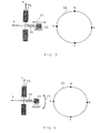
- a first test (test A) on the finite-element model consists in exciting the blown-up tyre not pressed to the ground by imposing a translation in the Y direction on the hub.
- the lateral displacement at particular points of the belt of the tyre and the force set up between hub and belt are measured.
- a schematic representation of the first test is shown in fig. 3 depicting belt 32, hub 33 in transverse section and a connection spring 34, which represents the lateral stiffness and damping between belt and hub.
- an arrow 31 representing the displacement imposed on the hub in the Y direction, and a side view of the belt 32, in which the cardinal points N, E, S and W are shown.
- the belt is symmetrical, the lateral displacement of one cardinal point only of the belt 32 is considered in this test.
- a first comparison test (A) is carried out on the concentrated-parameter tyre model, as will be illustrated later.
- the frequency responses of the quantities measured in these first two tests are compared and the errors minimized, the following concentrated parameters of the model 1 may then be determined:
- a second test (test B) on the finite-element model consists in exciting the blown-up tyre not pressed to the ground by imposing a camber rotation on the hub.
- the lateral displacement at particular points of the belt (camber rotation) and the torque transmitted between hub and belt are measured.
- a schematic representation of the second test is shown in fig. 4 depicting the belt 32, the hub 33 in transverse section and a connection spring 35, which schematically represents the camber torsional stiffness and damping between belt and hub, respectively K c ⁇ x and R c ⁇ x .
- Also shown are an arrow 41 representing the rotation imposed on the hub about the X axis, and a side view of the belt 32, in which the cardinal points N, E, S and W are indicated.
- the belt is symmetrical, the lateral displacement of one cardinal point only of the belt 32, selected indifferently between points N and S, is considered in this test.
- a second comparison test (B) is carried out on the concentrated-parameter tyre model, as will be illustrated later. Again in this case, when the frequency responses of the quantities measured in these second two tests (lateral displacement of a cardinal point of the belt and torque between belt and hub) are compared and the errors minimized, the following concentrated parameters of the model 1 may then be determined:
- connection between hub and belt is made in like manner for both the camber rotations and the yaw rotations and it is possible to consider that the behaviour of the belt not pressed to the ground is axial-symmetrical.
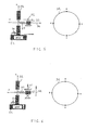
- a third test (test C) on the finite-element model consists in exciting the tyre blown up, pressed to the ground and bereft of its tread (rasped) at least in the area of contact by the application to the hub of a force in the Y direction. The lateral displacement of the hub and particular points of the belt are measured.
- a schematic representation of the third test is shown in fig. 5 depicting the belt 32, the hub 33 in transverse section, a connection spring 36 (in addition to the one described above, indicated with numeral 35) which schematically represents the residual, lateral and camber stiffnesses and dampings between belt and ground 24.
- an arrow 51 representing the force imparted
- an arrow 52 representing the lateral displacement of the hub
- a front view of the belt 32 in which the cardinal points N, E, S and W are indicated.
- the lateral displacement of the N and E cardinal points of the belt 32 is considered.
- a third comparison test (C) is carried out on the concentrated-parameter tyre model, as will be illustrated later.
- the frequency responses of the quantities measured in these third two tests are compared and the errors minimized, the following concentrated parameters of the model 1 may then be determined:
- a fourth test (test D) on the finite-element model consists in exciting the tyre blown up, pressed to the ground and bereft of its tread (rasped) at least in the area of contact by the application to the hub of a yawing torque about the Z axis. The yaw rotation of the hub and the displacement at particular points of the belt are measured.
- a schematic representation of the fourth test is shown in fig. 6 depicting the belt 32, the hub 33 in transverse section, a connection spring 37 (in addition to the one described above, indicated with numeral 35) which schematically represents the residual yawing stiffnesses and dampings between belt and ground 24.
- an arrow 61 representing the yawing torque imparted
- an arrow 62 representing the rotation of the hub
- a front view of the belt 32 in which the cardinal points N, E, S and W are indicated.
- the lateral displacement of the E and W cardinal points of the belt 32 is considered.
- a fourth comparison test (D) is carried out on the concentrated-parameter tyre model, as will be illustrated later.
- the frequency responses of the quantities measured in these fourth two tests yaw rotation of the hub and displacement of the E and W cardinal points of the belt
- the following concentrated parameters of the model 1 may then be determined:
- the stiffness and damping values already identified in the first and second tests are also modified in order to better describe the transfer functions given by the finite-element model.
- the stiffness and damping values between hub and belt are therefore modified slightly from those identified earlier.
- the tests A and B are carried out with the tyre blown up and not pressed to the ground, imposing displacements on the hub.
- the frequency responses must now be determined of the quantities measured in the tests A and B to be able to compare the frequency responses given by the finite-element model with the frequency responses of the concentrated-parameter model.
- the frequency response is obtained for the degree of freedom y c upon variation of ⁇ , that is to say the frequency response of the lateral displacement of the belt with respect to the hub.
- y c A M c . ⁇ 2 .
- an error is obtained that is a function of M c , K cy and R cy .
- this error is minimized, that is to say, values are chosen for M c, K cy and R cy that make the error minimum.
- C hub-belt B ( K c ⁇ x + i. ⁇ .R c ⁇ x ). D.e i ⁇ t
- the free degrees of freedom and the constrained degrees of freedom of the physical model are determined in the two test situations and an axial force is imposed on the hub in the Y direction, in the test C, and a yawing torque about the Z axis, in the test D.
- the equations of motion (1.7) and (1.8)
- the equations of motion for the free degrees of freedom of the physical model are obtained and the complex vector of the free degrees of freedom is determined. This vector contains both the modulus and the phase of the free degrees of freedom in question.
- the frequency responses of the lateral displacement of the hub, of the N point and of the E point of the belt are determined.
- the difference is computed between the frequency response obtained from the finite-element model and that obtained from the concentrated-parameter physical model and a second error is obtained which is a function of K ry , R ry , K r ⁇ x and R r ⁇ x .
- K ry , R ry , K r ⁇ x and R r ⁇ x On minimizing this error, the above-mentioned quantities are determined.
- the frequency responses are determined of the yaw rotation of the hub and of the displacement of the E point of the belt in relation to the quantities K r ⁇ z and R r ⁇ z . These quantities are determined by minimizing the error resulting as the difference between the frequency response provided by the finite-element model and that provided by the concentrated-parameter physical model.
- the stiffness K d is an important parameter for the purposes of definition of the tyre in that it provides an indication of the effect that the design parameters have on the drift behaviour.
- the resolving equation is: wherein: is a matrix (2,2).
- the first element of the first row of this matrix represents the total stiffness of the tyre K d :
- K d K ee (1,1)
- the total camber stiffness K ⁇ of the tyre provides an indication of the tyre's ability to exit from a longitudinal track, namely parallel to the direction of movement of the tyre, made on the road when the tyre is moving with rectilinear motion.
- the method according to the invention enables calculation of K ⁇ without the need to make and test a tyre prototype, as is generally done.
- a virtual test is carried out consisting in imposing a selected camber angle on the hub, with a null drift angle, and in measuring the sideward force created on the hub.
- the results obtained are brought into the procedure for the identification of the concentrated parameters of the physical model of a tyre of the 55 range (H/C section ratio of 0.55) manufactured by the Applicant.
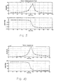
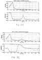
- the frequency response obtained with the concentrated-parameter physical model is represented with a continuous line, while the frequency response obtained with the finite-element model during the tests A, B, C and D is represented with asterisks.
- Fig. 7 is a graph of the frequency response of the displacement of a point of the belt obtained during the test A from the physical model and from the finite-element model
- fig. 8 is a graph of the frequency response of the force created between the hub and the belt, again in the test A.
- the frequency response has a single resonance peak.
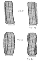
- a mode of vibration of the tyre illustrated in fig. 16 This mode of vibration maintains the tread band substantially rigid and may therefore be described by the concentrated-parameter model, that simulates the sidewall and the belt with a rigid ring.
- the parameters identified are therefore valid in a set of frequencies ranging from 0 to 100 Hz, since modes of vibration that considerably deform both sidewall and belt appear with frequencies that are higher than this.
- Fig. 9 is a graph of the frequency response of the displacement of a point of the belt obtained during the test B from the physical model and from the finite-element model
- fig. 10 is a graph of the frequency response of the torque created between the hub and the belt, again in the test B.
- Fig. 11 is a graph of the frequency response of the lateral displacement of the hub obtained from the physical model and from the finite-element model during the test C, with a normal load of 2,914 N bearing on the tyre
- figs. 12 and 13 are graphs of the frequency response of the lateral displacements of the E and N points of the belt, again in the test C.
- the modes of vibration maintain the sidewall and belt complex substantially rigid and may therefore be described accurately by the concentrated-parameter model, in other words the concentrated-parameter model is valid in the range of frequencies between 0 and 100 Hz.
- Fig. 14 is a graph of the frequency response of the yaw rotation of the hub obtained from the physical model and from the finite-element model during the test D, with a normal load of 2,914 N bearing on the tyre
- fig. 15 is a graph of the frequency response of the lateral displacement of the E point of the belt, again in the test D.
- K d 500 - 2,000 [N/g]
- K ⁇ 40 - 3,500 [N/g]
- K c 8,000 - 30,000 [N/g]
- the method according to the invention enables an evaluation to be made of the steady state behaviour of the drifting tyre.
- the bidirectional brush model shown in fig. 1 and illustrated above is used.
- the microinserts of the brush model become deformed and a sideward force and a moment of torque act on the beam that they are connected to. These forces and moments result in a deformation of the beam that affects the configuration of the microinserts.
- the deformation effectively assumed by the beams in relation to the drift angle imposed on the hub is determined.
- the total sideward force is determined, together with the total self-aligning torque acting on the plate that the beams are connected to.
- the plate snakes by an angle that depends on the overlying structure, i.e. on the springs connecting it to the hub.
- the deformation of the microinserts is altered.
- the sideward force and self-aligning torque that the tyre summons up in reaction to the drift angle imposed are determined.
- a drift angle ⁇ is applied to the physical model 1, starting from a condition in which the beams 22 are in a non-deformed configuration and the brush model has a null snaking ⁇ b (block 45).
- the sideward forces acting on the beams through the effect of the drift angle ⁇ and depending on the difference ⁇ - ⁇ b and on the deformation of the beams are determined (blocks 46a, 46b and 46c).
- the deformation of the beams is determined (blocks 47a, 47b and 47c).
- a check is made to see if the deformation is the same as that determined in the previous step (blocks 48a, 48b and 48c).
- the procedure for determining deformation of the beams is repeated until deformation is verified to be equal to that found in the previous step.
- the snaking of the plate i.e. of the brush model
- a check is made to see if the snaking is equal to that calculated in the previous step (block 50).
- the procedure for determining snaking of the plate is repeated until snaking is verified to be equal to that found in the previous step.
- the sideward force and the self-aligning torque acting on the hub due to the drift angle imposed are determined (block 51). The procedure is repeated for the different values of the drift angle ⁇ to produce drift, force and self-aligning torque curves that enable steady state drift behaviour of the tyre to be evaluated.
- the beams of the brush model do not all become deformed in the same way since the pressure distribution acting on each beam is different, as also are the sideward forces.
- the sidewalls of the tyre shoulder
- a distributed parameters model is used based on a model depicted in fig. 23 wherein the equivalent beams and springs (microinserts) of the brush model are indicated with the same numerals as in fig. 1.
- a linear static analysis corresponding to a sideways traction and made by applying a sideward force to the contact surface of the road, is then conducted on the finite-element model.
- the accordingly stressed tyre becomes deformed and the lateral displacements are determined at circumferential sections thereof, on a level with the external band. These circumferential sections are divided into three groups corresponding to the central part of the area of contact and to the two parts at either side.
- the mean lateral displacement of each group is calculated over the full length of the contact area.
- a "difference" deformation is obtained that must be offset by the equivalent beam of flexural stiffness EJ (N*m 2 ).
- a flexural stiffness EJ is determined for each beam.
- a static pressure distribution is determined on a non-rolling tyre with no drift.
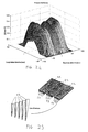
- the pressure distribution determined under a 55 range tyre, quoted earlier, is illustrated in fig. 24, with a normal acting load of 2,914 N. Similar distributions were determined with normal loads of 4,611 N and 6,302 N.
- the pressure values in those points where the microinserts of the brush model are present must be known beforehand.
- the contact was represented in the concentrated-parameter physical model by means of a regular grid of 200 x 15 elements (200 elements longitudinally and 3 x 5 elements transversally). Accordingly, the pressure at the nodes of this grid must be known, i.e. at 3,000 points.
- the finite-element model provides the pressure at a much lower number of points arranged in an irregular grid.
- a procedure for the interpolation of the finite-element model data is used to move from the grid of points provided by the finite-element model to that required by the concentrated-parameter model. In the case in hand, the procedure adopted is that of the "inverse distances". This interpolation procedure requires the following inputs:
- the procedure provides the pressure value for the points required.
- each microinsert of the brush model has an own length and a known pressure distribution. More specifically, the length of the contact of each microinsert changes upon variation of the transversal position considered and each microinsert has an own pressure value that depends on its position within the contact. Therefore the curve of the contacts of each microinsert, which identifies the position of the bottom ends of the microinserts when the tyre is drifting, varies from one microinsert to the next.
- Fig. 26 illustrates the deformation undergone by the beam due to the effect of the sideward forces transmitted by the microinserts and the deformations undergone by the microinserts.
- the deformations of the microinserts are given by the relative displacements between the upper ends (attached to the beam) and the lower ends (located on the line of contacts in the event of adhesion). Pattern of the pressure in each microinsert is illustrated in fig. 27.
- the total stiffnesses of the whole tread are taken and then the values found are divided by the total length of the microinserts obtained as the sum of those of the single microinserts: where 2a is the length of the area of contact, l tot is the sum of the lengths of the single microinserts, c py is the stiffness per unit of length of the contact and k tor is the torsional stiffness per unit of length of the contact.
- the flexure of the inserts present in the footprint area of the concentrated-parameter model is identified, the sum is obtained of the contributions of each and the value obtained subtracted from the torque per foot provided by the finite-element model.
- the shape of the area of contact is provided by the finite-element model. In this way, the purely twisting torque arising following rotation about the Z axis of the tyre pressed to the ground is obtained.
- the sideward force produced following deformation of each microinsert and contributing to the flexure, assuming perfect adhesion, is equal to the lateral stiffness of the microinsert multiplied by the relative displacement in the plane of the contact of the top end with respect to the bottom end of the microinsert.
- the deformation of a generic microinsert is equal to d (x, y) * ⁇ ', where ⁇ ' is the rotation about the Z axis effectively undergone by the tread and d is the distance of the microinsert taken from the centre of the contact.
- M f ( x, y ) F ( x, y ). d ( x, y ) where F is the sideward force due to the flexure of the microinsert and x and y are the coordinates as measured from the centre of the contact.
- the total bending torque created under the area of contact for the rotation a' is calculated as follows:
- the drift curves for the range 55 tyre were determined for three different loads.
- a pear-shaped area of contact is identified and a brush model with equivalent beams of different lengths is used, as depicted in fig. 28.
- the length of the beams is obtained by performing a sensitivity analysis, assuming that the central beam is equal in length to the statistically measured contact area length and that the variation of length of the external and internal beams is of equal modulus, but opposite sign.
- the sensitivity analysis was conducted on the range 55 tyre.
- the shape of the area of contact affects the transversal pressure distribution: the pressure peak corresponding to the outside of the curve is no longer equal to the other one (the external pressure peak increases, whereas the internal one decreases as the drift angle increases). It is considered that the pressure distribution in the transverse direction is always less symmetrical with a higher pressure peak in correspondence with the longest equivalent beam and a lower pressure peak in correspondence with the shortest equivalent beam.
- the sideward forces arising under the contact are calculated for different drift angles through the concentrated-parameter physical model as described earlier.
- This force distribution is applied to the nodes of the finite-element model (non-rolling) in contact with the ground and an extremely realistic indication of the pressure distribution in the area of contact obtained. From the pressure distributions obtained, a strong symmetry in the transverse direction results. Illustrated in fig. 29 is the pattern of pressure distribution (N/mm 2 ) for a vertical load of 2,914 N whenever a sideward force and a self-aligning torque corresponding to a test with drift of 6° are applied to the finite-element model.
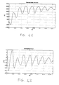
- Figs. 30 and 31 illustrate respectively the pattern of the sideward force (N) and the self-aligning torque (Nm) in relation to the drift angle ⁇ (°) for a vertical load of 2,914 N.
- the calculated values are marked with asterisks (*), whereas the experimental values are marked with circles (o). Similar curves were obtained for normal loads of 4,611 N and 6,302 N.
- the tyre is made roll by imposing laws of motion on the hub that vary with time and are suitable for numerically reproducing selected experimental tests commonly carried out on tyres.
- Fig. 32 illustrates a cinematic diagram of a test machine with the pendulum arrangement.
- Fig. 33 illustrates a cinematic diagram of a test machine with the yaw arrangement.
- the longitudinal and transverse components of the velocity of the centre of the hub are defined as follows:
- the steering angle imposed on the hub is equal to the drift angle.
- the independent variables of the physical model 1 with nine degrees of freedom are again those indicated above (1.1).
- the equations of motion governing the motion of the physical model are again those in matrix form reported above (1.7).
- the matrix of mass and that of stiffness are those reported above at (1.4) and (1.5).
- the damping matrix is that given above at (1.6), wherein the terms (5,3), (5,6) and (6,5) are equal to J y ⁇ y (moment of inertia and angular speed about the Y axis) to take gyroscopic effects into account.
- the vector of the forces comprises:
- F l represents the vector containing the external active forces acting on the actual degrees of freedom; in this case, the only external forces acting on the x l are the sideward force F by and the self-aligning torque M bz created under the contact and acting on the degrees of freedom of the plate. These forces depend on the arrangement of deformation of the inserts and on whether or not there is local slipping; they are therefore, generally speaking, non-linear functions of the degrees of freedom.
- F v represents the vector of the generalized reactions applied to the constrained degrees of freedom.
- the equation (1.59) therefore represents a system of "n" equations, one for each unknown x l ; by solving this equation, the motion x l of the model can be determined.
- the constraining reactions F v may be obtained from the equations for the constrained degrees of freedom.
- Equation (1.59) On rearranging the already rearranged matrices of mass, stiffness and damping as described above, and performing a division into four submatrices, the equation (1.59) becomes: where F and c is a vector of three elements containing the generalized forces acting directly on the degrees of freedom of the belt and F and b is a vector of two elements containing the generalized forces acting directly on the degrees of freedom of the brush model (F by and M bz ).
- the forces arising during the transient state depend on the trajectory of the top and bottom ends of each microinsert and are, as stated, influenced by the motion of the wheel.
- the deformation of a generic i-th microinsert is defined as follows: Y i_T ( x i , t ) - Y i_P ( x i ,t ) where Y i-P is understood to be the absolute lateral displacement of the top end of the i-th microinsert connected to the plate and Y i-T is understood to be the absolute lateral displacement of the bottom end interacting with the ground.
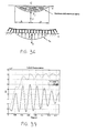
- FIG. 34 A procedure enabling an instant-by-instant evaluation of the displacements of the top and bottom ends of all the microinserts in the contact is now illustrated with reference to figs. 34 and 35.
- the plate 21 of fig. 1, connecting the belt to the microinserts in a generic configuration, is illustrated in schematic form, seen from above, in fig. 34. Having earlier indicated the absolute lateral displacement of the plate with y b and its absolute yaw with ⁇ b , the absolute lateral displacement of the top end of the generic microinsert Y i-P is : Y i_P ( x i , t ) Y b ( t ) + ( a - ⁇ i ). sin ( ⁇ b ) where ⁇ i is the abscissa indicating the generic microinsert in the reference integral with the wheel (fig. 34).
- a generic microinsert is taken at the generic instant of time at which it enters the contact area: the top and bottom ends, seen from above, are at the same point because the microinsert has not yet been deformed.
- the top end of the generic microinsert has a longitudinal displacement component V * t opposite to the feed direction of the tyre while, at the same time, due to the effect of the absolute lateral displacement of the plate y b and of its yaw ⁇ b , it also has a transverse direction component.
- the bottom end of said microinsert assuming perfect adhesion, remains motionless in the absolute reference system whereas, in the reference system integral with the wheel, it possesses a displacement component V * t in the longitudinal direction.
- V * t Having set a distance between two adjacent microinserts of V * dt in correspondence with each step of integration of the dynamic equations described above, a single microinsert enters and exits from the contact (fig. 35). Three successive instants of time are taken. At the instant t, the microinsert 1 has just entered under the contact and is in the deformed configuration.
- the non-linearity of the brush model results from the possibility of whether the microinserts slip or not.
- Two factors have a fundamental role in this: the coefficient of friction at the interface between the wheel and ground and the pressure distribution.
- a side view is shown of the reference model, at the bottom of fig. 36.
- the pressure distribution is assumed to be parabolic in the longitudinal direction, whereas no pattern need be defined for the transverse direction since the brush model considered is monodimensional.
- the normal forces per unit of length that are discharged to the ground are: where F z is the vertical load applied to the tyre.
- the maximum deformation possible for the generic microinsert is: where ⁇ is the coefficient of friction between tyre and ground and c py is the stiffness per unit of length of the brush model.
- the test was conducted on a range 55 tyre with an applied vertical load of 2,914 N and a steering angle of four degrees imposed on the hub.
- the feed speed of the tyre was 30 Km/h.
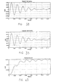
- Fig. 37 shows the time pattern of the lateral displacement of the belt y c with respect to the hub and of the absolute lateral displacement of the plate y b .
- the time pattern is shown respectively of the snaking ⁇ c of the belt, of the snaking ⁇ b of the plate and of the roll ⁇ c of the belt.
- Figs. 41 and 42 illustrate the time pattern respectively of the sideward force F by and of the self-aligning torque M bz .
- the pattern of the sideward force F by is used to evaluate the length of relaxation which consists of the space travelled by the tyre before the sideward force reaches 63.2% of its steady state value.
- the signal of the sideward force F by is removed of its high frequency harmonics.
- a low-pass filter was used with cutoff frequency 30 Hz (fig. 43).
- the filtered signal is comparable to the response of a 1 st order system receiving a step signal as its input.
- a * x 0 is the steady state value of F.
- the relaxation length was found to be 0.23 metres.
- Figs. 45-47 illustrate the results obtained with the range 55 tyre for three different loads and with different yaw angles imposed on the hub with feeding speed of 100 Km/h.
- the resulting sideward force and the self-aligning torque are determined by integrating the forces q y distributed along the beam.
- the constraining reactions F a and F b are determined in order to give the deformation curve.
- F a - F y 2 + M z 2* a
- F b - F y 2 - M z 2* a
- This equation is resolved by determining the bending torque in each section of the beam.
- Figs. 48, 49 and 50 illustrate the pattern respectively of the sideward force, of the self-aligning torque, of the length of relaxation at steady state in relation to the steering angle, with a rigid and deformable contact, for the range 55 tyre to which a vertical load of 2,914 N is applied.
- Figs. 51 and 52 illustrate respectively the pattern of the length of relaxation and of the time constant in relation to velocity for the range 55 tyre to which three vertical loads of 2,914 N, 4,611 N and 6,302 N were applied.
Landscapes
- Engineering & Computer Science (AREA)
- Physics & Mathematics (AREA)
- Geometry (AREA)
- General Physics & Mathematics (AREA)
- Computer Hardware Design (AREA)
- General Engineering & Computer Science (AREA)
- Theoretical Computer Science (AREA)
- Mechanical Engineering (AREA)
- Computational Mathematics (AREA)
- Aviation & Aerospace Engineering (AREA)
- Mathematical Analysis (AREA)
- Mathematical Optimization (AREA)
- Pure & Applied Mathematics (AREA)
- Evolutionary Computation (AREA)
- Automation & Control Theory (AREA)
- Tires In General (AREA)
- Control Of Driving Devices And Active Controlling Of Vehicle (AREA)
Priority Applications (1)
| Application Number | Priority Date | Filing Date | Title |
|---|---|---|---|
| EP99201029A EP0949496B1 (fr) | 1998-04-07 | 1999-04-01 | Méthode de détermination de la condition de circulation des pneumatiques de véhicules |
Applications Claiming Priority (3)
| Application Number | Priority Date | Filing Date | Title |
|---|---|---|---|
| EP98830209 | 1998-04-07 | ||
| EP98830209 | 1998-04-07 | ||
| EP99201029A EP0949496B1 (fr) | 1998-04-07 | 1999-04-01 | Méthode de détermination de la condition de circulation des pneumatiques de véhicules |
Publications (2)
| Publication Number | Publication Date |
|---|---|
| EP0949496A1 true EP0949496A1 (fr) | 1999-10-13 |
| EP0949496B1 EP0949496B1 (fr) | 2007-12-12 |
Family
ID=8236609
Family Applications (1)
| Application Number | Title | Priority Date | Filing Date |
|---|---|---|---|
| EP99201029A Expired - Lifetime EP0949496B1 (fr) | 1998-04-07 | 1999-04-01 | Méthode de détermination de la condition de circulation des pneumatiques de véhicules |
Country Status (5)
| Country | Link |
|---|---|
| US (2) | US6338270B1 (fr) |
| EP (1) | EP0949496B1 (fr) |
| JP (1) | JPH11321253A (fr) |
| AT (1) | ATE381004T1 (fr) |
| DE (1) | DE69937702T2 (fr) |
Cited By (8)
| Publication number | Priority date | Publication date | Assignee | Title |
|---|---|---|---|---|
| WO2003014693A1 (fr) * | 2001-08-06 | 2003-02-20 | Societe De Technologie Michelin | Methode de determination de composantes d'efforts subis par un pneumatique et du couple d'auto-alignement |
| US6962075B2 (en) | 2001-08-06 | 2005-11-08 | Michelin Recherche Et Technique S.A. | Method of determining characteristics of a tire from stresses |
| US7099765B2 (en) | 2002-02-08 | 2006-08-29 | Michelin Recherche Et Technique S.A. | Direct determination of the maximum grip coefficient on the basis of measurement of the circumferential extension in a sidewall of a tire |
| US7174244B2 (en) | 2003-08-13 | 2007-02-06 | Hyundai Motor Company | Suspension of a vehicle and method for controlling the same |
| CN106468623A (zh) * | 2016-09-26 | 2017-03-01 | 华南理工大学 | 一种整车状态下动力总成悬置系统刚体模态参数测试方法 |
| CN106596131A (zh) * | 2016-12-23 | 2017-04-26 | 奇瑞汽车股份有限公司 | 一种汽车白车身模态测试中激励力的位置、幅值以及方向的确定方法 |
| CN110188512A (zh) * | 2019-07-01 | 2019-08-30 | 东北大学 | 一种单双联卡箍管路系统建模的方法 |
| CN118082664A (zh) * | 2024-04-26 | 2024-05-28 | 山西承信新能源科技装备有限公司 | 一种四驱四转向矿车及其开闭系统 |
Families Citing this family (38)
| Publication number | Priority date | Publication date | Assignee | Title |
|---|---|---|---|---|
| DE19744725A1 (de) * | 1997-10-10 | 1999-04-15 | Itt Mfg Enterprises Inc | Verfahren zum Bestimmen von Zustandsgrößen eines Kraftfahrzeuges |
| DE69937702T2 (de) * | 1998-04-07 | 2008-12-04 | Pirelli Tyre S.P.A. | Verfahren zur Bestimmung des Strassenverhaltens eines Fahrzeugreifens |
| KR100325236B1 (ko) * | 1999-12-30 | 2002-03-04 | 이계안 | 타이어 유한요소 모델링 방법 |
| JP3498064B2 (ja) * | 2001-03-29 | 2004-02-16 | 住友ゴム工業株式会社 | タイヤ有限要素モデルの作成方法 |
| JP4913964B2 (ja) * | 2001-08-31 | 2012-04-11 | 東洋ゴム工業株式会社 | 実測値の推定方法及びそのプログラム |
| US7606690B2 (en) * | 2001-12-18 | 2009-10-20 | Nhk International Corporation | Method and apparatus for modeling coil springs using a force field generator |
| US7398146B2 (en) * | 2002-06-24 | 2008-07-08 | Michelin Recherche Et Technique S.A. | Measurement of the maximum adhesion coefficient by measuring stress in a bead of a tire |
| FR2841336A1 (fr) * | 2002-06-24 | 2003-12-26 | Michelin Soc Tech | Mesure du coefficient d'adherence maximal a partir de la mesure de contraintes dans un bourrelet d'un pneu |
| FR2843194A1 (fr) * | 2002-07-31 | 2004-02-06 | Soc Technologie Michelin Stm | Procede et disposiitif de determination d'un effort exerce sur une roue par le sol |
| JP3940093B2 (ja) * | 2003-04-28 | 2007-07-04 | 住友ゴム工業株式会社 | タイヤのシミュレーション方法 |
| US7469200B2 (en) * | 2003-05-14 | 2008-12-23 | Ford Global Technologies, Llc | Method and apparatus for predicting belt separation failure in aging tires by computer simulation |
| JP3876244B2 (ja) * | 2003-09-19 | 2007-01-31 | 横浜ゴム株式会社 | タイヤのパラメータ値導出方法、タイヤのコーナリング特性算出方法、タイヤの設計方法、車両の運動解析方法およびプログラム |
| US7110926B2 (en) * | 2003-10-29 | 2006-09-19 | Nhk International Corp. | Universal spring mechanism for automobile suspension system design |
| US6945118B2 (en) * | 2004-01-13 | 2005-09-20 | Honeywell International Inc. | Ceramic on metal pressure transducer |
| US7373287B2 (en) * | 2004-08-09 | 2008-05-13 | Bridgestone Firestone North American Tire, Llc | Finite element analysis tire footprint smoothing algorithm using multiple load cases |
| JP4608306B2 (ja) * | 2004-12-21 | 2011-01-12 | 住友ゴム工業株式会社 | タイヤのシミュレーション方法 |
| US7363805B2 (en) * | 2005-09-30 | 2008-04-29 | Ford Motor Company | System for virtual prediction of road loads |
| JP4747798B2 (ja) * | 2005-11-22 | 2011-08-17 | 東洋ゴム工業株式会社 | タイヤ摩耗試験方法 |
| EP1798648B1 (fr) * | 2005-12-13 | 2017-03-15 | Sumitomo Rubber Industries, Ltd. | Procédé de simulation de pneu |
| DE602006006794D1 (de) * | 2006-03-23 | 2009-06-25 | Ferrari Spa | Reifen-Modell mit reduziertem Massstab für aerodynamische Tests im Windkanal |
| US8176933B2 (en) * | 2006-07-28 | 2012-05-15 | Hydril Usa Manufacturing Llc | Annular BOP packing unit |
| US20080023917A1 (en) * | 2006-07-28 | 2008-01-31 | Hydril Company Lp | Seal for blowout preventer with selective debonding |
| US7865299B2 (en) * | 2006-09-14 | 2011-01-04 | Toyota Motor Engineering & Manufacturing North America, Inc. | Method and system for predicting a future position of a vehicle using numerical integration |
| WO2008133353A1 (fr) * | 2007-04-25 | 2008-11-06 | Toyota Jidosha Kabushiki Kaisha | Dispositif de détection de force d'action de pneu |
| US8401827B2 (en) * | 2008-04-14 | 2013-03-19 | Daa Draexlmaier Automotive Of America Llc | Processing device and method for structure data representing a physical structure |
| US7784334B2 (en) * | 2008-08-15 | 2010-08-31 | Ford Global Technologies, Llc | Camber angle optimization for a biaxial wheel test machine |
| JP4860680B2 (ja) | 2008-12-03 | 2012-01-25 | トヨタ自動車株式会社 | タイヤ作用力検出装置 |
| US8006550B2 (en) * | 2009-04-13 | 2011-08-30 | GM Global Technology Operations LLC | Methods and systems for testing tires of vehicles to quantify transient tire force and moment responses |
| JP5011361B2 (ja) * | 2009-09-25 | 2012-08-29 | 株式会社神戸製鋼所 | タイヤ試験機 |
| EP2801835B1 (fr) * | 2011-12-26 | 2019-07-24 | The University of Tokyo | Procédé et dispositif de mesure |
| KR101675362B1 (ko) * | 2012-04-11 | 2016-11-11 | 브리지스톤 어메리카스 타이어 오퍼레이션스, 엘엘씨 | 롤링하는 타이어의 정상 상태 시뮬레이션용의 시스템 및 방법 |
| KR101338828B1 (ko) * | 2013-07-30 | 2013-12-06 | 군산대학교산학협력단 | 타이어의 조종안정성능 평가방법 및 평가시스템 |
| JP6366410B2 (ja) * | 2014-08-01 | 2018-08-01 | 東洋ゴム工業株式会社 | タイヤのフォースバリエーションを算出する方法、装置及びコンピュータプログラム |
| EP4434770A3 (fr) | 2019-04-01 | 2024-11-27 | Bridgestone Americas Tire Operations, LLC | Système et procédé d'inférence bayésienne dans la caractérisation et la prédiction de l'usure d'un pneu de véhicule |
| WO2021070410A1 (fr) * | 2019-10-08 | 2021-04-15 | 株式会社エー・アンド・デイ | Dispositif d'essai de pneu |
| US11562137B2 (en) | 2020-04-14 | 2023-01-24 | Bank Of America Corporation | System to correct model drift for natural language understanding |
| CN112818462B (zh) * | 2020-12-31 | 2024-05-07 | 东风小康汽车有限公司重庆分公司 | 车轮参数模型的生成方法、装置、存储介质和计算机设备 |
| CN116811490B (zh) * | 2023-05-29 | 2026-04-24 | 青岛森麒麟轮胎股份有限公司 | 侧向松弛长度的获取方法及应用 |
Citations (2)
| Publication number | Priority date | Publication date | Assignee | Title |
|---|---|---|---|---|
| EP0647911A2 (fr) * | 1993-10-06 | 1995-04-12 | Bridgestone Corporation | Méthode pour concevoir des bandages pneumatiques |
| EP0775902A1 (fr) * | 1995-11-21 | 1997-05-28 | PIRELLI COORDINAMENTO PNEUMATICI S.p.A. | Procédé de contrÔle pour la détermination du niveau de confort d'un pneu d'une roue de véhicule |
Family Cites Families (5)
| Publication number | Priority date | Publication date | Assignee | Title |
|---|---|---|---|---|
| IT1279059B1 (it) | 1995-11-21 | 1997-12-04 | Pirelli | Pneumatico avente caratteristiche ottimali per il comfort di marcia di un veicolo |
| IT1277226B1 (it) | 1995-11-21 | 1997-11-05 | Pirelli | Dispositivo per una prova di frenata e trazione di una ruota comprendente un cerchio e un pneumatico |
| IT1279062B1 (it) | 1995-11-21 | 1997-12-04 | Pirelli | Apparecchiatura per una prova di superamento ostacolo di una ruota comprendente un cerchio e un pneumatico |
| IT1279061B1 (it) | 1995-11-21 | 1997-12-04 | Pirelli | Vibratore torsionale |
| DE69937702T2 (de) * | 1998-04-07 | 2008-12-04 | Pirelli Tyre S.P.A. | Verfahren zur Bestimmung des Strassenverhaltens eines Fahrzeugreifens |
-
1999
- 1999-04-01 DE DE69937702T patent/DE69937702T2/de not_active Expired - Lifetime
- 1999-04-01 AT AT99201029T patent/ATE381004T1/de not_active IP Right Cessation
- 1999-04-01 EP EP99201029A patent/EP0949496B1/fr not_active Expired - Lifetime
- 1999-04-06 US US09/286,671 patent/US6338270B1/en not_active Expired - Lifetime
- 1999-04-07 JP JP11099517A patent/JPH11321253A/ja active Pending
-
2001
- 2001-04-26 US US09/842,409 patent/US6761060B2/en not_active Expired - Lifetime
Patent Citations (2)
| Publication number | Priority date | Publication date | Assignee | Title |
|---|---|---|---|---|
| EP0647911A2 (fr) * | 1993-10-06 | 1995-04-12 | Bridgestone Corporation | Méthode pour concevoir des bandages pneumatiques |
| EP0775902A1 (fr) * | 1995-11-21 | 1997-05-28 | PIRELLI COORDINAMENTO PNEUMATICI S.p.A. | Procédé de contrÔle pour la détermination du niveau de confort d'un pneu d'une roue de véhicule |
Cited By (10)
| Publication number | Priority date | Publication date | Assignee | Title |
|---|---|---|---|---|
| WO2003014693A1 (fr) * | 2001-08-06 | 2003-02-20 | Societe De Technologie Michelin | Methode de determination de composantes d'efforts subis par un pneumatique et du couple d'auto-alignement |
| US6962075B2 (en) | 2001-08-06 | 2005-11-08 | Michelin Recherche Et Technique S.A. | Method of determining characteristics of a tire from stresses |
| US7203603B2 (en) | 2001-08-06 | 2007-04-10 | Michelin Recherche Et Technique S.A. | Method of determining components of forces exerted on a tire and determining the self-alignment torque |
| US7099765B2 (en) | 2002-02-08 | 2006-08-29 | Michelin Recherche Et Technique S.A. | Direct determination of the maximum grip coefficient on the basis of measurement of the circumferential extension in a sidewall of a tire |
| US7174244B2 (en) | 2003-08-13 | 2007-02-06 | Hyundai Motor Company | Suspension of a vehicle and method for controlling the same |
| CN106468623A (zh) * | 2016-09-26 | 2017-03-01 | 华南理工大学 | 一种整车状态下动力总成悬置系统刚体模态参数测试方法 |
| CN106596131A (zh) * | 2016-12-23 | 2017-04-26 | 奇瑞汽车股份有限公司 | 一种汽车白车身模态测试中激励力的位置、幅值以及方向的确定方法 |
| CN110188512A (zh) * | 2019-07-01 | 2019-08-30 | 东北大学 | 一种单双联卡箍管路系统建模的方法 |
| CN110188512B (zh) * | 2019-07-01 | 2022-12-13 | 东北大学 | 一种单双联卡箍管路系统建模的方法 |
| CN118082664A (zh) * | 2024-04-26 | 2024-05-28 | 山西承信新能源科技装备有限公司 | 一种四驱四转向矿车及其开闭系统 |
Also Published As
| Publication number | Publication date |
|---|---|
| JPH11321253A (ja) | 1999-11-24 |
| DE69937702T2 (de) | 2008-12-04 |
| DE69937702D1 (de) | 2008-01-24 |
| EP0949496B1 (fr) | 2007-12-12 |
| US6761060B2 (en) | 2004-07-13 |
| US20010020386A1 (en) | 2001-09-13 |
| US6338270B1 (en) | 2002-01-15 |
| ATE381004T1 (de) | 2007-12-15 |
| US20020014114A1 (en) | 2002-02-07 |
Similar Documents
| Publication | Publication Date | Title |
|---|---|---|
| EP0949496B1 (fr) | Méthode de détermination de la condition de circulation des pneumatiques de véhicules | |
| US7363805B2 (en) | System for virtual prediction of road loads | |
| CN101639409B (zh) | 模拟滚动轮胎的方法 | |
| CN101510230A (zh) | 车辆道路载荷的仿真方法 | |
| EP1600758A2 (fr) | Uniformité de pneu améliorée par compensation entre les variations de faux-ronds et de rigidités | |
| US6871162B2 (en) | Non-iterative method for a fully-coupled thermomechanical analysis of a tire and estimating effects of compound changes on tire temperature distribution using the deformation index | |
| Santiciolli et al. | Simulation of the scenario of the biaxial wheel fatigue test | |
| Gipser | Adams/ftire-a tire model for ride & durability simulations | |
| KR100305835B1 (ko) | 차체의 내구력 평가 해석 방법 | |
| CN113962134B (zh) | 条件生成式对抗网络与载荷应变线性叠加的应变监测方法 | |
| EP1798648B1 (fr) | Procédé de simulation de pneu | |
| Bernard et al. | Tire models for the determination of vehicle structural loads | |
| Mancosu et al. | A Mathematical‐physical 3D Tire Model for Handling/Comfort Optimization on a Vehicle: Comparison with Experimental Results | |
| KR100370275B1 (ko) | 유연 다물체 동력학 시뮬레이션에 의한 차량구조물의동응력 해석방법 | |
| Mousseau et al. | The dynamic response of spindle forces produced by a tire impacting large obstacles in a plane | |
| Wei | A finite element based approach to characterising flexible ring tire (FTire) model for extended range of operating conditions | |
| K Billal et al. | Simulation of vehicle pothole test and techniques used | |
| JP2022037666A (ja) | タイヤのシミュレーション方法 | |
| WO2009116048A2 (fr) | Procédé pour la modélisation d’élément à point de cosserat (cpe) de matériaux élastiques non linéaires | |
| Shiraishi et al. | Making FEM tire model and applying it for durability simulation | |
| Darnell et al. | Analysis of tire force and moment response during side slip using an efficient finite element model | |
| Majcher et al. | Analysis of vehicle suspensions with static and dynamic computer simulations | |
| Cho et al. | Numerical simulation of radiation noise of 3-D smooth tire using the rebound excitation force at the bending front | |
| Baecker et al. | A method to combine a tire model with a flexible rim model in a hybrid MBS/FEM simulation setup | |
| Pir et al. | Integrated model-based approach for the optimisation of vehicle ride comfort and handling characteristics: integrated vehicle dynamics model design |
Legal Events
| Date | Code | Title | Description |
|---|---|---|---|
| PUAI | Public reference made under article 153(3) epc to a published international application that has entered the european phase |
Free format text: ORIGINAL CODE: 0009012 |
|
| AK | Designated contracting states |
Kind code of ref document: A1 Designated state(s): AT DE ES FR GB IT LU PT SE |
|
| AX | Request for extension of the european patent |
Free format text: AL;LT;LV;MK;RO;SI |
|
| 17P | Request for examination filed |
Effective date: 20000401 |
|
| AKX | Designation fees paid |
Free format text: AT DE ES FR GB IT LU PT SE |
|
| RAP1 | Party data changed (applicant data changed or rights of an application transferred) |
Owner name: PIRELLI TYRE S.P.A. |
|
| 17Q | First examination report despatched |
Effective date: 20060922 |
|
| GRAP | Despatch of communication of intention to grant a patent |
Free format text: ORIGINAL CODE: EPIDOSNIGR1 |
|
| GRAS | Grant fee paid |
Free format text: ORIGINAL CODE: EPIDOSNIGR3 |
|
| GRAA | (expected) grant |
Free format text: ORIGINAL CODE: 0009210 |
|
| AK | Designated contracting states |
Kind code of ref document: B1 Designated state(s): AT DE ES FR GB IT LU PT SE |
|
| REG | Reference to a national code |
Ref country code: GB Ref legal event code: FG4D |
|
| REF | Corresponds to: |
Ref document number: 69937702 Country of ref document: DE Date of ref document: 20080124 Kind code of ref document: P |
|
| PG25 | Lapsed in a contracting state [announced via postgrant information from national office to epo] |
Ref country code: SE Free format text: LAPSE BECAUSE OF FAILURE TO SUBMIT A TRANSLATION OF THE DESCRIPTION OR TO PAY THE FEE WITHIN THE PRESCRIBED TIME-LIMIT Effective date: 20080312 |
|
| PG25 | Lapsed in a contracting state [announced via postgrant information from national office to epo] |
Ref country code: AT Free format text: LAPSE BECAUSE OF FAILURE TO SUBMIT A TRANSLATION OF THE DESCRIPTION OR TO PAY THE FEE WITHIN THE PRESCRIBED TIME-LIMIT Effective date: 20071212 |
|
| PG25 | Lapsed in a contracting state [announced via postgrant information from national office to epo] |
Ref country code: ES Free format text: LAPSE BECAUSE OF FAILURE TO SUBMIT A TRANSLATION OF THE DESCRIPTION OR TO PAY THE FEE WITHIN THE PRESCRIBED TIME-LIMIT Effective date: 20080323 |
|
| ET | Fr: translation filed | ||
| PG25 | Lapsed in a contracting state [announced via postgrant information from national office to epo] |
Ref country code: PT Free format text: LAPSE BECAUSE OF FAILURE TO SUBMIT A TRANSLATION OF THE DESCRIPTION OR TO PAY THE FEE WITHIN THE PRESCRIBED TIME-LIMIT Effective date: 20080512 |
|
| PLBE | No opposition filed within time limit |
Free format text: ORIGINAL CODE: 0009261 |
|
| STAA | Information on the status of an ep patent application or granted ep patent |
Free format text: STATUS: NO OPPOSITION FILED WITHIN TIME LIMIT |
|
| 26N | No opposition filed |
Effective date: 20080915 |
|
| PGFP | Annual fee paid to national office [announced via postgrant information from national office to epo] |
Ref country code: FR Payment date: 20080417 Year of fee payment: 10 |
|
| PGFP | Annual fee paid to national office [announced via postgrant information from national office to epo] |
Ref country code: GB Payment date: 20080429 Year of fee payment: 10 |
|
| GBPC | Gb: european patent ceased through non-payment of renewal fee |
Effective date: 20090401 |
|
| REG | Reference to a national code |
Ref country code: FR Ref legal event code: ST Effective date: 20091231 |
|
| PG25 | Lapsed in a contracting state [announced via postgrant information from national office to epo] |
Ref country code: GB Free format text: LAPSE BECAUSE OF NON-PAYMENT OF DUE FEES Effective date: 20090401 Ref country code: FR Free format text: LAPSE BECAUSE OF NON-PAYMENT OF DUE FEES Effective date: 20091222 |
|
| PG25 | Lapsed in a contracting state [announced via postgrant information from national office to epo] |
Ref country code: LU Free format text: LAPSE BECAUSE OF NON-PAYMENT OF DUE FEES Effective date: 20080401 |
|
| PGFP | Annual fee paid to national office [announced via postgrant information from national office to epo] |
Ref country code: DE Payment date: 20160427 Year of fee payment: 18 |
|
| PGFP | Annual fee paid to national office [announced via postgrant information from national office to epo] |
Ref country code: IT Payment date: 20160421 Year of fee payment: 18 |
|
| REG | Reference to a national code |
Ref country code: DE Ref legal event code: R119 Ref document number: 69937702 Country of ref document: DE |
|
| PG25 | Lapsed in a contracting state [announced via postgrant information from national office to epo] |
Ref country code: DE Free format text: LAPSE BECAUSE OF NON-PAYMENT OF DUE FEES Effective date: 20171103 |
|
| PG25 | Lapsed in a contracting state [announced via postgrant information from national office to epo] |
Ref country code: IT Free format text: LAPSE BECAUSE OF NON-PAYMENT OF DUE FEES Effective date: 20170401 |