EP0949601A2 - Vorrichtung zur Präsentation von Informationen - Google Patents
Vorrichtung zur Präsentation von Informationen Download PDFInfo
- Publication number
- EP0949601A2 EP0949601A2 EP99106153A EP99106153A EP0949601A2 EP 0949601 A2 EP0949601 A2 EP 0949601A2 EP 99106153 A EP99106153 A EP 99106153A EP 99106153 A EP99106153 A EP 99106153A EP 0949601 A2 EP0949601 A2 EP 0949601A2
- Authority
- EP
- European Patent Office
- Prior art keywords
- presentation
- information carriers
- frame
- elements
- area
- Prior art date
- Legal status (The legal status is an assumption and is not a legal conclusion. Google has not performed a legal analysis and makes no representation as to the accuracy of the status listed.)
- Withdrawn
Links
Images


Classifications
-
- G—PHYSICS
- G09—EDUCATION; CRYPTOGRAPHY; DISPLAY; ADVERTISING; SEALS
- G09F—DISPLAYING; ADVERTISING; SIGNS; LABELS OR NAME-PLATES; SEALS
- G09F1/00—Cardboard or like show-cards of foldable or flexible material
- G09F1/10—Supports or holders for show-cards
-
- G—PHYSICS
- G09—EDUCATION; CRYPTOGRAPHY; DISPLAY; ADVERTISING; SEALS
- G09F—DISPLAYING; ADVERTISING; SIGNS; LABELS OR NAME-PLATES; SEALS
- G09F15/00—Boards, hoardings, pillars, or like structures for notices, placards, posters, or the like
- G09F15/0006—Boards, hoardings, pillars, or like structures for notices, placards, posters, or the like planar structures comprising one or more panels
- G09F15/0056—Boards, hoardings, pillars, or like structures for notices, placards, posters, or the like planar structures comprising one or more panels portable display standards
- G09F15/0062—Boards, hoardings, pillars, or like structures for notices, placards, posters, or the like planar structures comprising one or more panels portable display standards collapsible
Definitions
- the present invention relates to a device for presenting information on information carriers with at least one presentation area, the at least one presentation area can be set up or hung on the wall or ceiling.
- Presentation devices in the form of billboards, advertising columns and the like are already known for a long time.
- Information carriers e.g. For example, in the form of posters.
- these types of presentation devices are not suitable.
- Smaller information carriers can e.g. For example, be attached to devices in the manner of pin boards. That kind of presentation However, it is relatively unsafe because the information carriers can be easily removed and nothing more be replaced.
- the object of the present invention is therefore to provide a device of the type mentioned above, with the help of which small-format information carriers can be effectively presented.
- the solution is that the presentation area with presentation elements for recording one or more information carriers is provided.
- small-format information carriers can thus be easily produced present effectively.
- Several similar information carriers are combined in one Presentation element assembled and can be removed by interested people. It can be z.
- business cards, brochures, leaflets and similar products act. This type of presentation is particularly well suited for small format information carriers and very effective.
- the device according to the invention is particularly suitable for use in the entrance area of shopping malls, supermarkets, hardware stores, home improvement stores, department stores and the like.
- the presentation surface of the device according to the invention is fixed in a frame.
- This frame can be a holding frame for wall or ceiling mounting, an assembly frame with a support device or a two or more part frame, the parts against each other can be mobile.
- Another preferred form is the design in the form of a Screens.
- the presentation areas can also, with or without a frame, in the form of a fanfold be designed.
- Both the presentation area and the frame can be made of any material. Metal, plastics of all types and wood are particularly preferred.
- the presentation elements into which the information carriers can preferably be inserted or inserted are z.
- containers attached to the presentation wall for holding information carriers be.
- the presentation elements can also be integrated into the presentation wall be, e.g. B. in the form of pockets or slots for receiving the information carrier.
- the presentation elements can also be labeled to indicate the ones they contain Point out information carriers and refill with the same or from the same sender to simplify originating information carriers.
- Another advantageous development sees before that presentation elements for the inclusion of similar, z. B. of the same format or with Information carriers provided with the same information or originating from the same sender are arranged on the presentation area in the immediate vicinity of each other and are labeled accordingly.
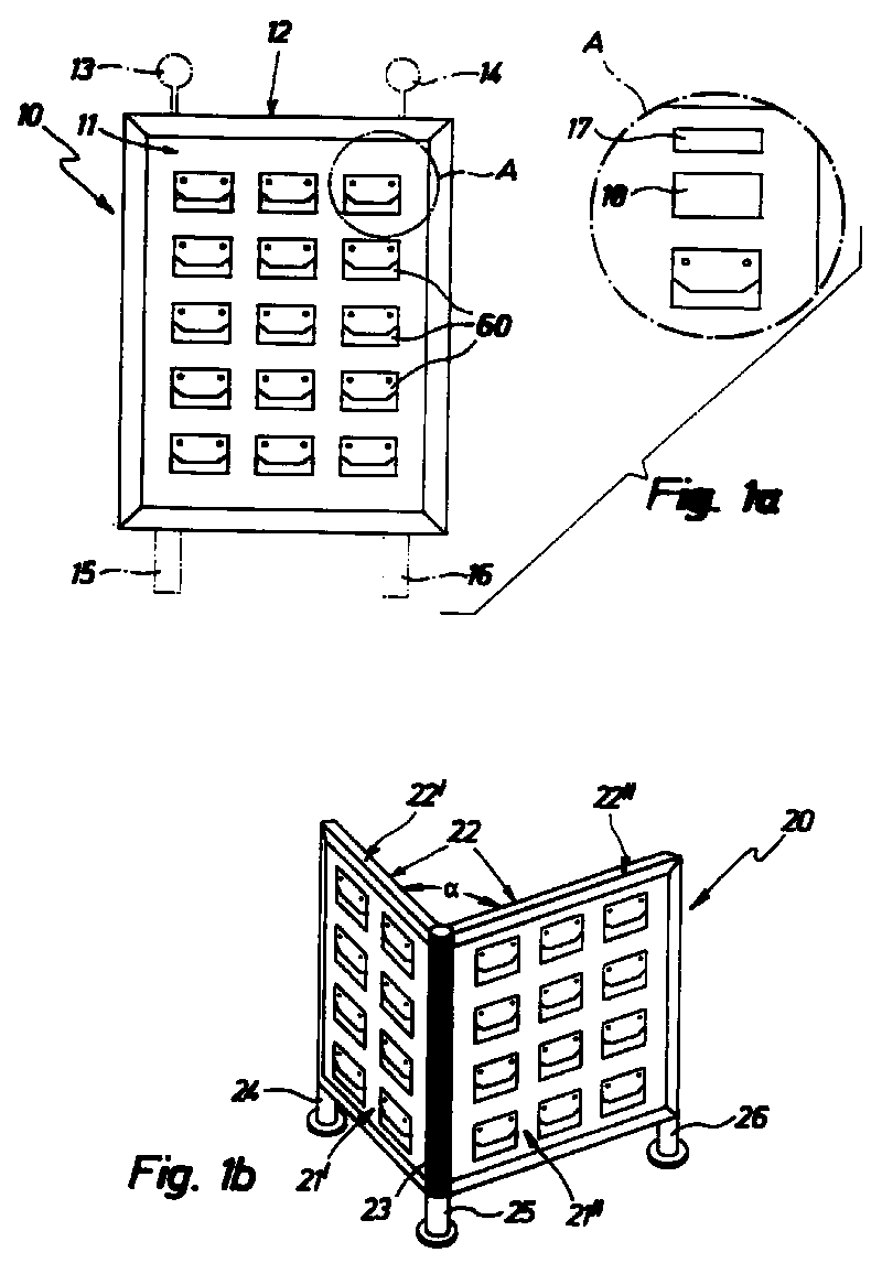
- the devices 10, 20, 30 shown in FIGS. 1a-1c each have one or more Presentation areas 11, 21 'and 21' 'as well as 31 and 31' on, which by a frame 12, 22, 32 or 32 'is fixed.
- the only presentation surface 11 is in the essentially rectangular and fixed in a one-piece frame 12.
- the presentation area 11 is For example, from a foiled wooden plate, plastic or metal, while the frame 12 Light metal can exist.
- the section enlargement A illustrates that 60 devices above the presentation elements 17 can be provided for inscription, for example.
- a plastic or industry label Metal This makes it easy for the user of the device according to the invention to select the desired one Find information or the desired information carrier.
- devices 18 be provided for fastening a single information carrier.
- the assignment of the individual presentation elements 60 documented so that the presentation elements z. Ex. Reliable can always be replenished with the same information carriers. Other possibilities labeling and inventory are of course also possible.
- the device 20 shown in FIG. 1b has two presentation surfaces 21 'and. 21 '' on. Both presentation surfaces 21 ', 21' 'are fixed via a two-part frame 22 and together connected. Each of the presentation areas 21 ', 21' 'is fixed with a frame 22', 22 '', e.g. For example in the manner as shown in Figure 1.
- the two subframes 22 'and 22' ' are common vertical frame profile 23 connected to each other and are at a certain angle ⁇ , z. Example 45 °, set up to each other.
- the lower parts of the subframes 22 ', 22' ' have support elements 24, 25, 26 on.
- the two subframes 22 ', 22' ' can also be against each other via a common axis of rotation moved and set up at a certain angle ⁇ to each other.
- the device 30 shown in Figure 1c has two presentation surfaces 31, 31 ', which in one Frames 32, 32 'are fixed.
- the frame 32, 32 'in turn is part of a support device 33, which is essentially a gesture consisting of four legs 34, 35, 36, 37. Two legs each 34, 35 and 36, 37 run parallel to each other. The four legs 34, 35, 36, 37 open into one Cross member 38.
- the cross member 38 simultaneously represents an axis of rotation over which the pairs of legs 34, 35 or 36, 37 and thus the presentation surfaces 31, 31 'at an angle ⁇ to each other are mobile.
- the device 30 can also have only a single presentation area 31 be provided.
- the exemplary embodiment of a device 40 according to the invention shown in FIG. 2 has none Frame on, but a presentation area 41, which in numerous approximately rectangular partial areas 41a - 41g is divided.
- the individual partial areas 41a-41g are in each case common Longitudinal edges 42a - 42f articulated together so that they form a kind of fanfold.
- Over a further edge 43 is a terminal partial surface 41 a with a fastening element 44 connected to attach the entire presentation surface 41 to a wall or the like.
- One or more presentation elements 60 can be provided on each partial surface 41a-41g be.
- FIG. 3 shows a further exemplary embodiment of a device 50 according to the invention, which is similar how the device shown in Figure 2 is constructed, but with the individual presentation areas 51a - 51h can be set up like a screen.
- the roughly rectangular presentation areas 51a - 51h are in turn articulated to one another via a common longitudinal edge 52a - 52g connected.
- the individual presentation areas can be provided with a frame 53 be, e.g. For example in the manner as shown in Figure 1b.
- On the presentation areas 51a - 51g numerous presentation elements are again provided (not shown here).
- FIGS. 4a-4d Various embodiments of presentation elements are shown in FIGS. 4a-4d. These forms are only examples; other shapes and formats are a matter of course possible and placed at the discretion of the specialist.
- FIG. 4a shows a presentation element 60 in the form of a box 61 for holding information carriers shown.
- the box 61 is provided with a fastening element 66, with which it can be attached to the presentation surface of a device according to the invention can.
- the box 61 is approximately cuboid and has four side walls 62 to 65 and one Floor 66 on.
- the rear side wall 65 merges into the fastening element 66.
- the front side wall 64 is somewhat lower in its central region 64 'than in its edge regions 64 '' and 64 '' ', so that the information carriers inside the box 61 are more easily accessible.
- Spacers 67 may also be provided on the rear side wall 65.
- the presentation element 60 'shown in FIG. 4b has a similar structure, but the box is 61 'round in cross section instead of rectangular.
- FIG. 4c shows a further presentation element in the form of an integrated one in the presentation surface 11 Pocket 70 shown.
- the pocket 70 can be made of the same material as the presentation surface 11; however, this is not mandatory.
- the pocket 70 has a front side 71, which from the Level of the presentation surface 11 can be folded out, so that several information carriers can be inserted are. When unfolding, side walls 72 fold out, which together with the front 71 and the presentation surface 11 form a container for receiving information carriers.
- FIG. 4d shows a further presentation element integrated into the presentation surface 11 an insertion flap or an insertion slot 70 '.
- FIGS. 5 and 6 show schematically how several frame parts are put together in this way can be that two or more presentation areas at a certain angle to each other can be set up as z.
- Example is shown in Figure 1b.
- FIG. 5 schematically shows an embodiment of a frame part 80.
- the frame part 80 is made of Light metal, but can also be made of other materials, e.g. For example, plastic or wood. It has a rectangular cross section with two flat sides 81, 82 and two narrow sides 83, 84. A longitudinal groove 85, 86 is provided in each of the narrow sides 83, 84, into which a presentation wall can be inserted.
- On the front side 87 of the frame part 80 is a connecting element 88 provided.
- FIG. 6 schematically shows a vertical support profile 90.
- the support profile 90 has a cross section circular central support element 91, on the outer circumference 92 outer Support elements 93 are provided, which include recesses 94 between them.
- Several horizontally extending frame parts 80 can by means of their connecting element 88 in a certain Angle can be reversibly attached to a vertical support profile 90 and fixed.
- the Frame parts 80 can also be plugged onto a presentation wall along their longitudinal grooves 85, 86 become. In this way, an easily mountable device according to the invention is obtained in lightweight construction.
- the exemplary embodiments just described are the subject matter not limit the present invention, but only have an exemplary function. core Rather, the invention is a device in which on one or more presentation surfaces Presentation elements are provided that can hold information carriers.
Landscapes
- Physics & Mathematics (AREA)
- General Physics & Mathematics (AREA)
- Engineering & Computer Science (AREA)
- Theoretical Computer Science (AREA)
- Devices For Indicating Variable Information By Combining Individual Elements (AREA)
- Mirrors, Picture Frames, Photograph Stands, And Related Fastening Devices (AREA)
Abstract
Description
- Figuren 1a - 1c
- schematische Darstellungen verschiedener Ausführungsformen der erfindungsgemäßen Vorrichtung;
- Figur 2
- eine schematische Darstellung einer weiteren Ausführungsform in Form eine Leporellos;
- Figur 3
- eine schematische Darstellung einer weiteren Ausführungsform in Form eines Paravents;
- Figuren 4a - 4d
- verschiedene Ausführungsformen von Präsentationselementen für die erfindungsgemäße Vorrichtung;
- Figur 5
- eine schematische Darstellung einer Ausführungsform eines Rahmenteils;
- Figur 6
- eine schematische Darstellung eines Stützenprofils für das in Figur 5 gezeigte Rahmenteil.
Claims (10)
- Vorrichtung (10, 20, 30, 40, 50) zur Präsentation von Informationen auf Informationsträgern, mit mindestens einer Präsentationsfläche (11, 21, 31, 41, 51), wobei mindestens eine Präsentationsfläche aufstellbar oder an der Wand oder der Decke aufhängbar ist, dadurch gekennzeichnet, daß die mindestens eine Präsentationsfläche (11, 21, 31, 41, 51,) mit Präsentationselementen (60, 60', 70, 70') zur Aufnahme eines oder mehrerer Informationsträger versehen ist.
- Vorrichtung nach Anspruch 1, dadurch gekennzeichnet, daß die Präsentationsfläche in einem Rahmen (12, 22, 32, 53) fixiert ist.
- Vorrichtung nach Anspruch 2, dadurch gekennzeichnet, daß der Rahmen ein Stellrahmen (32) mit einer Stützvorrichtung (33) ist.
- Vorrichtung nach Anspruch 2 oder 3, dadurch gekennzeichnet, daß der Rahmen (12, 22, 32, 52) aus Metall, beliebigem Kunststoff, oder Holz besteht.
- Vorrichtung nach einem der vorhergehenden Ansprüche, dadurch gekennzeichnet, daß sie in Form eines Leporellos (40) oder Paravents (50) mit mindestens zwei Präsentationsteilflächen (41a - 41g, 51a - 51h) gestaltet ist.
- Vorrichtung nach einem der vorhergehenden Ansprüche, dadurch gekennzeichnet, daß die Präsentationsfläche aus Metall, einem beliebigen Kunststoff oder Holz besteht.
- Vorrichtung nach einem der vorhergehenden Ansprüche, dadurch gekennzeichnet, daß die Informationsträger in die Präsentationselemente (60, 60', 70, 70') einsteckbar oder einlegbar sind.
- Vorrichtung nach einem der vorhergehenden Ansprüche, dadurch gekennzeichnet, daß die Präsentationselemente an der Präsentationsfläche befestigte Behältnisse (60, 60') zur Aufnahme von Informationsträgern sind.
- Vorrichtung nach einem der Ansprüche 1 bis 7, dadurch gekennzeichnet, daß die Präsentationselemente in die Präsentationsfläche integrierter Taschen (70) oder Einstecköffnungen (70') zur Aufnahme von Informationsträgern sind.
- Vorrichtung nach einem der vorhergehenden Ansprüche, dadurch gekennzeichnet, daß Präsentationselemente für gleichartige Informationsträger gemeinsam bzw. in unmittelbarer Nachbarschaft zueinander angeordnet sind.
Applications Claiming Priority (2)
| Application Number | Priority Date | Filing Date | Title |
|---|---|---|---|
| DE29806529U | 1998-04-09 | ||
| DE29806529U DE29806529U1 (de) | 1998-04-09 | 1998-04-09 | Vorrichtung zur Präsentation von Informationen |
Publications (2)
| Publication Number | Publication Date |
|---|---|
| EP0949601A2 true EP0949601A2 (de) | 1999-10-13 |
| EP0949601A3 EP0949601A3 (de) | 1999-11-24 |
Family
ID=8055566
Family Applications (1)
| Application Number | Title | Priority Date | Filing Date |
|---|---|---|---|
| EP99106153A Withdrawn EP0949601A3 (de) | 1998-04-09 | 1999-04-07 | Vorrichtung zur Präsentation von Informationen |
Country Status (2)
| Country | Link |
|---|---|
| EP (1) | EP0949601A3 (de) |
| DE (1) | DE29806529U1 (de) |
Family Cites Families (3)
| Publication number | Priority date | Publication date | Assignee | Title |
|---|---|---|---|---|
| US3608221A (en) * | 1969-12-08 | 1971-09-28 | Museum Planning Inc | Display panel |
| GB8712171D0 (en) * | 1987-05-22 | 1987-06-24 | Marler Haley Expostems Ltd | Display frame |
| US5092062A (en) * | 1988-11-02 | 1992-03-03 | Palka Mike F | Display device |
-
1998
- 1998-04-09 DE DE29806529U patent/DE29806529U1/de not_active Expired - Lifetime
-
1999
- 1999-04-07 EP EP99106153A patent/EP0949601A3/de not_active Withdrawn
Also Published As
| Publication number | Publication date |
|---|---|
| DE29806529U1 (de) | 1999-09-02 |
| EP0949601A3 (de) | 1999-11-24 |
Similar Documents
| Publication | Publication Date | Title |
|---|---|---|
| DE60011236T2 (de) | Vorrichtung zur informationsanzeige | |
| DE3614351C2 (de) | ||
| EP0712527B1 (de) | Preiskassette | |
| EP0949601A2 (de) | Vorrichtung zur Präsentation von Informationen | |
| DE3614352C2 (de) | ||
| DE29501171U1 (de) | Objektträger für zwei- und dreidimensionale Objekte | |
| CH678238A5 (de) | ||
| DE102019106576B4 (de) | Beschriftungsleiste | |
| DE8526839U1 (de) | Einkaufswagen | |
| DE3909983C1 (en) | Hollow placard panel | |
| DE2835679C3 (de) | Halterung für Informationstafeln | |
| DE4300770C2 (de) | Bahnförmige Haltetaschen aus federndem Kunststoff für streifenförmige Aufzeichnungsträger an einer Planungstafel | |
| DE1889285U (de) | Verkaufsstaender. | |
| DE8613948U1 (de) | Verkaufständer für Gegenstände, insbesondere Scheren, Messer u.dgl. | |
| DE7817600U1 (de) | Traeger fuer informationsmittel | |
| DE8530751U1 (de) | Werbeträger für einen Einkaufswagen od. dgl. | |
| DE9001838U1 (de) | Tablett | |
| DE3425226A1 (de) | Wandverkleidung oder raumtrennwand aus metallenen vertikal- und tafelelementen | |
| DE8233046U1 (de) | Zettelbox | |
| DE3028215A1 (de) | Schildhalter | |
| DE9314586U1 (de) | Karte oder Plakat | |
| CH686716A5 (de) | Karte oder Plakat sowie Verfahren zur Herstellung. | |
| DE3526617A1 (de) | Bauelementensatz zum aufbau eines staenders zur darbietung und werbepraesentation kleinerer verkaufsgegenstaende | |
| DE29510946U1 (de) | Vorrichtung zur Aufbewahrung und/oder Präsentation von CD-Behältern aus Blech, insbesondere aus Stahlblech | |
| DE7600749U1 (de) | Namensschild |
Legal Events
| Date | Code | Title | Description |
|---|---|---|---|
| PUAI | Public reference made under article 153(3) epc to a published international application that has entered the european phase |
Free format text: ORIGINAL CODE: 0009012 |
|
| PUAL | Search report despatched |
Free format text: ORIGINAL CODE: 0009013 |
|
| AK | Designated contracting states |
Kind code of ref document: A2 Designated state(s): AT CH DE DK ES FR GB IT LI NL SE |
|
| AX | Request for extension of the european patent |
Free format text: AL;LT;LV;MK;RO;SI |
|
| AK | Designated contracting states |
Kind code of ref document: A3 Designated state(s): AT BE CH CY DE DK ES FI FR GB GR IE IT LI LU MC NL PT SE |
|
| AX | Request for extension of the european patent |
Free format text: AL;LT;LV;MK;RO;SI |
|
| RIC1 | Information provided on ipc code assigned before grant |
Free format text: 6G 09F 7/08 A, 6G 09F 15/00 B, 6G 09F 1/10 B |
|
| 17P | Request for examination filed |
Effective date: 20000410 |
|
| AKX | Designation fees paid |
Free format text: AT CH DE DK ES FR GB IT LI NL SE |
|
| 17Q | First examination report despatched |
Effective date: 20010417 |
|
| STAA | Information on the status of an ep patent application or granted ep patent |
Free format text: STATUS: THE APPLICATION IS DEEMED TO BE WITHDRAWN |
|
| 18D | Application deemed to be withdrawn |
Effective date: 20010828 |