EP0949723A1 - Elektrischer hermaphroditischer Sicherheitssteckverbinder - Google Patents
Elektrischer hermaphroditischer Sicherheitssteckverbinder Download PDFInfo
- Publication number
- EP0949723A1 EP0949723A1 EP99400853A EP99400853A EP0949723A1 EP 0949723 A1 EP0949723 A1 EP 0949723A1 EP 99400853 A EP99400853 A EP 99400853A EP 99400853 A EP99400853 A EP 99400853A EP 0949723 A1 EP0949723 A1 EP 0949723A1
- Authority
- EP
- European Patent Office
- Prior art keywords
- connector
- contact
- parts
- hermaphroditic
- connector according
- Prior art date
- Legal status (The legal status is an assumption and is not a legal conclusion. Google has not performed a legal analysis and makes no representation as to the accuracy of the status listed.)
- Granted
Links
Images


Classifications
-
- H—ELECTRICITY
- H01—ELECTRIC ELEMENTS
- H01R—ELECTRICALLY-CONDUCTIVE CONNECTIONS; STRUCTURAL ASSOCIATIONS OF A PLURALITY OF MUTUALLY-INSULATED ELECTRICAL CONNECTING ELEMENTS; COUPLING DEVICES; CURRENT COLLECTORS
- H01R13/00—Details of coupling devices of the kinds covered by groups H01R12/70 or H01R24/00 - H01R33/00
- H01R13/44—Means for preventing access to live contacts
- H01R13/447—Shutter or cover plate
- H01R13/453—Shutter or cover plate opened by engagement of counterpart
-
- H—ELECTRICITY
- H01—ELECTRIC ELEMENTS
- H01R—ELECTRICALLY-CONDUCTIVE CONNECTIONS; STRUCTURAL ASSOCIATIONS OF A PLURALITY OF MUTUALLY-INSULATED ELECTRICAL CONNECTING ELEMENTS; COUPLING DEVICES; CURRENT COLLECTORS
- H01R24/00—Two-part coupling devices, or either of their cooperating parts, characterised by their overall structure
- H01R24/84—Hermaphroditic coupling devices
-
- H—ELECTRICITY
- H01—ELECTRIC ELEMENTS
- H01R—ELECTRICALLY-CONDUCTIVE CONNECTIONS; STRUCTURAL ASSOCIATIONS OF A PLURALITY OF MUTUALLY-INSULATED ELECTRICAL CONNECTING ELEMENTS; COUPLING DEVICES; CURRENT COLLECTORS
- H01R13/00—Details of coupling devices of the kinds covered by groups H01R12/70 or H01R24/00 - H01R33/00
- H01R13/62—Means for facilitating engagement or disengagement of coupling parts or for holding them in engagement
- H01R13/627—Snap or like fastening
- H01R13/6275—Latching arms not integral with the housing
Definitions
- the invention relates to a hermaphrodite connector of safety, closed by masking the contacts, and intended including power transmission.
- a hermaphrodite electrical connector is consisting of two connector parts, movable plug and base, strictly identical. Such a limit connector therefore the number of connector parts in storage per continuation of the identity of the base and the plug and protects the corresponding plug parts, applied one on the other, the risk of fouling.
- the power transmission at a voltage greater than 48 volts requires contact safety masking.
- a connector is proposed according to the invention electric hermaphrodite safety, especially for the power transmission, consisting of two parts of identical connectors, connected to each other in service, characterized in that it comprises for each part of connector at least one electrical contact disposed in the median plane of the connector, and a shutter flap of the contact, protecting the contact from intrusion, and opening when the connector parts are plugged in.
- the plug-in is obtained by presenting the parts of opposite connector, oriented 180 ° from each other.
- Said shutter is advantageously rotatably mounted at the front of said contact, being shaped and rotated so adequate so that it closes the access of the contact in position out of service and makes it accessible for plugging in.
- the contact is preferably a mounted end contact movable and recalled forward, axially, and likewise the shutter can be mounted movable axially recalled forward, so that when plugging in after opening of the shutter, the latter is driven backwards through the other connector part for allow contacting with pressure of said contacts opposite the connector parts.
- the shutter is movably mounted in rotation, axially, in a movable block mounted sliding axially in the body and recalled forward.
- the axial stroke of the movable block or flap shutter is greater than that of the contact (the offset of rear positioning of the contact relative to the block or shutter).
- the connector body has a path for guidance, for example with lugs and complementary grooves, guiding the insertion and extraction of the parts of connector, one with respect to the other, the plug being lockable in position by a hooking device manually releasable and projecting the extraction of the parts connector when disconnected, to limit any phenomenon electric arc at contact breakage.
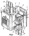
- the electrical connector hermaphrodite according to the invention consists of two identical connector parts 1 and 1 ', intended to be plugged into each other, opposite each other by their front part.
- One of the parts can be mobile and constitute the plug part of the connector and the other constitute the part base.
- the plugging is carried out following a first movement transverse then a second axial movement (according to arrows), the lateral pins 3 of the front skirt 5 of one of the connector parts 1 'being engaged in grooves additional 7 'L-shaped from the other part of connector 1 'and vice versa for pins 3' in the S grooves 7.
- the locking of the plug-in is obtained at the end with two opposite external hooks 9 and 9 'whose nose 10, 10' on one of the parts engages in a respective complementary projecting part 11 ′, 11 on the other (see Figure 7).
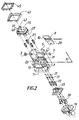
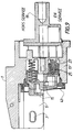
- Each connector part has a body 13 essentially rectangular parallelepiped, provided with a front skirt 5, a front movable block 15, a side hook 9, pins internal contacts 17 and a connected rear cap part 19 to electrically conductive cables 21.
- the front skirt 5 extends on one side of the body 13, that of greater width, being cut with a section in U, comprising the lateral hook 9 at its front end and two lateral pins 3 for guiding the plugging, fixed on its wings.
- the movable block 15 is mounted to slide axially in a complementary recess before 23 of the body, being recalled forward by means of four springs 25 each mounted in a rear corner sleeve 27 of the block.
- the lateral hook 9 is articulated on the wall upper part of the skirt, being recalled by its pusher part rear 29 up, in the grip direction on the other connector part.
- the contact pins 17, three in number, are also slidably mounted axially in the body 13, passing through it and the movable block 15 by holes of adequate aligned holes 31, being recalled forward by helical springs 33 supported in drums complementary 35 back of a body bottom plate and on a middle flange 37 of pin 17.
- the pins 17 are arranged in a longitudinal median plane P.
- the rear cap part 19 carries screw sockets wire clamp 39, at the rear of which the cables are fixed conductors 21.
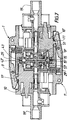
- the sockets 39 have in their sleeve before internal cells 41, which receive with electrical contact link contact pins electric 17, mounted sliding inside by their rear part (see figures 6, 7).
- a flexible peripheral seal 43 fixed by means of a clamp 45 is arranged on the front part of the body, at the level of the movable block.
- This seal 43 applied to the top edge of the front recess 23 of the body is intended to bear with sealing ( Figure 7) on the corresponding seal 43 'of the other connector part in the inserted state.
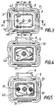
- This movable block 15 has three holes 31 of passage of the contact pins 17 in the inserted position, a upper front hook 47, and a lower recess 49 at the vertical of the hook 47.
- the hook 47 of a movable block 15 of a connector part 1 is intended to penetrate insertion (during the first transverse movement) into the corresponding recess 49 'of the movable block 15' on the other connector part 1 '. In doing so, it leads to the opening (FIG. 5) a shutter flap 51 of the pins contact, rotatably mounted axially inside the block mobile and recalled when closing ( Figure 4) by means of a spiral spring 53 (visible in Figure 6).
- connector The operation of the connector is now described. he is to present face to face the two parts of connector 1 and 1 'oriented 180 ° from each other, engage the lateral pins 3 and 3 'of the opposite skirts 5 and 5 'in the guide grooves 7' and 7 of the body, respectively, to exercise the first transverse movement transverse insertion, where the shutter flap 51 opens then to exert at manual pressure the second axial movement of plugging in at the end of which it is brought into contact end to end and in electrical connection the contact pins 17 and 17 '.
- Disconnection is obtained in reverse by pressing the two pushers 29, 29 'of the hooks 9, 9' simultaneously. There is then a first extraction in axial projection automatic exerted on the grooves 7, 7 'of axial guide bodies, under the thrust essentially one against the other of the movable blocks 15, 15 'biased forward. And in a second step, we separate the parts transversely connector unlike the first plug-in movement.
- Variant embodiments can be imagined in the scope of the invention, for example as to the mode of guiding the connector parts to each other, the number of contacts, the possibility of having a mobile component without movable block, the possibility of translating the flap shutter in the movable block masking the contacts, the connector locking etc.
Landscapes
- Connector Housings Or Holding Contact Members (AREA)
- Details Of Connecting Devices For Male And Female Coupling (AREA)
Applications Claiming Priority (2)
| Application Number | Priority Date | Filing Date | Title |
|---|---|---|---|
| FR9804455A FR2777391B1 (fr) | 1998-04-09 | 1998-04-09 | Connecteur electrique hermaphrodite de securite |
| FR9804455 | 1998-04-09 |
Publications (2)
| Publication Number | Publication Date |
|---|---|
| EP0949723A1 true EP0949723A1 (de) | 1999-10-13 |
| EP0949723B1 EP0949723B1 (de) | 2002-11-27 |
Family
ID=9525065
Family Applications (1)
| Application Number | Title | Priority Date | Filing Date |
|---|---|---|---|
| EP99400853A Expired - Lifetime EP0949723B1 (de) | 1998-04-09 | 1999-04-08 | Elektrischer hermaphroditischer Sicherheitssteckverbinder |
Country Status (5)
| Country | Link |
|---|---|
| US (1) | US6109938A (de) |
| EP (1) | EP0949723B1 (de) |
| DE (1) | DE69904100T2 (de) |
| ES (1) | ES2188104T3 (de) |
| FR (1) | FR2777391B1 (de) |
Cited By (1)
| Publication number | Priority date | Publication date | Assignee | Title |
|---|---|---|---|---|
| EP2144336A1 (de) * | 2008-06-30 | 2010-01-13 | INARCA S.p.A. | Luftdichter zweipoliger oder mehrpoliger Stecker |
Families Citing this family (14)
| Publication number | Priority date | Publication date | Assignee | Title |
|---|---|---|---|---|
| US20090197478A1 (en) * | 2008-02-06 | 2009-08-06 | Mandel Larry M | Interlocking overmold for electronic assembly |
| GB2526005B (en) | 2011-09-02 | 2016-04-06 | Pag Ltd | Battery management system, method and battery |
| GB2494189A (en) * | 2011-09-02 | 2013-03-06 | Pag Ltd | Battery coupling arrangement |
| EP2872723A4 (de) | 2012-07-13 | 2016-01-27 | Halliburton Energy Services Inc | Drehbohrmeissel mit sicherheitsschneideelementen zur optimierung der lebensdauer des bohrmeissels |
| US9252539B2 (en) | 2012-11-02 | 2016-02-02 | Hubbell Incorporated | Internally switched female receptacle or connector with plug-latching safety interlock |
| US9653719B2 (en) | 2013-10-04 | 2017-05-16 | Pag Ltd. | Battery |
| CN104022411A (zh) * | 2014-05-14 | 2014-09-03 | 四川永贵科技有限公司 | 一种互耦式电连接装置 |
| US10027058B2 (en) | 2016-09-12 | 2018-07-17 | Standard Car Truck Company | Electrical connector |
| US9929490B1 (en) * | 2016-09-12 | 2018-03-27 | Standard Car Truck Company | Electrical connector |
| US10177497B2 (en) | 2016-09-12 | 2019-01-08 | Standard Car Truck Company | Electrical connector |
| US9887489B1 (en) | 2016-10-19 | 2018-02-06 | Hubbell Incorporated | Electrical connector with plug latching assembly |
| US10944206B1 (en) | 2018-12-17 | 2021-03-09 | OPDO Connectors, LLC | Electrical connector system with a latch that permits rotation of connector housings into electrical connection |
| TW202429783A (zh) * | 2020-12-10 | 2024-07-16 | 美商莫仕有限公司 | 高速的公母同體的連接器系統及其連接器 |
| CN117895280B (zh) * | 2024-03-18 | 2024-06-11 | 绵阳华岩电子有限公司 | 一种高强度连接及可靠屏蔽的互耦连接器 |
Citations (4)
| Publication number | Priority date | Publication date | Assignee | Title |
|---|---|---|---|---|
| DE2806496A1 (de) * | 1977-02-22 | 1978-08-31 | Itt Ind Gmbh Deutsche | Mehrfach-steckverbinder |
| EP0528735A1 (de) * | 1991-08-21 | 1993-02-24 | Société d'Exploitation des Procédés Maréchal S.E.P.M. (Société Anonyme) | Selektive Vorrichtung für elektrische Verbindung, welche mit einer Sicherheitsscheibe und einer komplementären Scheibe ausgerüstet ist |
| EP0626737A2 (de) * | 1993-04-07 | 1994-11-30 | Sumitomo Wiring Systems, Ltd. | Verbinder |
| EP0665454A1 (de) * | 1994-02-01 | 1995-08-02 | Hirose Electric Co., Ltd. | Verbinder |
Family Cites Families (9)
| Publication number | Priority date | Publication date | Assignee | Title |
|---|---|---|---|---|
| US2444843A (en) * | 1943-08-27 | 1948-07-06 | Modrey Patents Corp | Electrical plug and socket connector with retractable contacts |
| FR2501920A1 (fr) * | 1981-03-10 | 1982-09-17 | Socapex | Dispositif de connexion electrique pour le raccordement de cables a brins multiples |
| US4913514A (en) * | 1988-11-22 | 1990-04-03 | Advanced Optical Systems | Fiber optic connector |
| US4898543A (en) * | 1989-04-03 | 1990-02-06 | G & H Technology, Inc. | Self-aligning electrical connector |
| US5104333A (en) * | 1989-12-20 | 1992-04-14 | Yazaki Corporation | Connector apparatus |
| FR2703844B1 (fr) * | 1993-04-09 | 1995-05-24 | Sepm | Connecteur électrique et plus particulièrement connecteur de charge. |
| FR2727799B1 (fr) * | 1994-12-02 | 1997-01-17 | Marechal Sepm | Prise pour connexion electrique, a contacts proteges |
| US5685727A (en) * | 1995-01-20 | 1997-11-11 | Ocean Design, Inc. | Underwater mateable connector |
| US5800196A (en) * | 1996-08-21 | 1998-09-01 | Tri-Star Electronics International, Inc. | Hermaphroditic electrical connector |
-
1998
- 1998-04-09 FR FR9804455A patent/FR2777391B1/fr not_active Expired - Fee Related
-
1999
- 1999-04-07 US US09/287,518 patent/US6109938A/en not_active Expired - Lifetime
- 1999-04-08 EP EP99400853A patent/EP0949723B1/de not_active Expired - Lifetime
- 1999-04-08 ES ES99400853T patent/ES2188104T3/es not_active Expired - Lifetime
- 1999-04-08 DE DE69904100T patent/DE69904100T2/de not_active Expired - Lifetime
Patent Citations (4)
| Publication number | Priority date | Publication date | Assignee | Title |
|---|---|---|---|---|
| DE2806496A1 (de) * | 1977-02-22 | 1978-08-31 | Itt Ind Gmbh Deutsche | Mehrfach-steckverbinder |
| EP0528735A1 (de) * | 1991-08-21 | 1993-02-24 | Société d'Exploitation des Procédés Maréchal S.E.P.M. (Société Anonyme) | Selektive Vorrichtung für elektrische Verbindung, welche mit einer Sicherheitsscheibe und einer komplementären Scheibe ausgerüstet ist |
| EP0626737A2 (de) * | 1993-04-07 | 1994-11-30 | Sumitomo Wiring Systems, Ltd. | Verbinder |
| EP0665454A1 (de) * | 1994-02-01 | 1995-08-02 | Hirose Electric Co., Ltd. | Verbinder |
Cited By (1)
| Publication number | Priority date | Publication date | Assignee | Title |
|---|---|---|---|---|
| EP2144336A1 (de) * | 2008-06-30 | 2010-01-13 | INARCA S.p.A. | Luftdichter zweipoliger oder mehrpoliger Stecker |
Also Published As
| Publication number | Publication date |
|---|---|
| EP0949723B1 (de) | 2002-11-27 |
| FR2777391A1 (fr) | 1999-10-15 |
| US6109938A (en) | 2000-08-29 |
| ES2188104T3 (es) | 2003-06-16 |
| DE69904100D1 (de) | 2003-01-09 |
| FR2777391B1 (fr) | 2000-06-23 |
| DE69904100T2 (de) | 2003-07-17 |
Similar Documents
| Publication | Publication Date | Title |
|---|---|---|
| EP0949723B1 (de) | Elektrischer hermaphroditischer Sicherheitssteckverbinder | |
| CA2120870C (fr) | Connecteur electrique et plus particulierement connecteur de charge | |
| EP2523261B1 (de) | Dichte Verbindungseinheit | |
| EP0038745A1 (de) | Anordnung mit einer Kontaktklemme und mit einem mit dieser Klemme zusammenwirkenden Stecker zum unterbrechungsfreien Verbinden mit einem die Klemme tragenden Schaltkreis | |
| FR2513023A1 (de) | ||
| FR2612340A1 (fr) | Borne de raccordement multiple pour appareil electrique modulaire | |
| EP0505256B1 (de) | Zweiteiliger Adapter für den Anschluss eines elektrischen Gerätes mit Stecker an eine Wandsteckdose | |
| FR2609845A1 (fr) | Dispositif pour tester un ou plusieurs cables munis d'une prise male | |
| CA1243343A (fr) | Prise de courant plus particulierement destinee aux courants de forte intensite | |
| FR3049778A1 (fr) | Connecteur electrique a dispositif d'assurance de position de connecteur rotatif | |
| FR2934091A1 (fr) | Prise de courant a fond de puits mobile et obturateur escamotable | |
| EP0112258B1 (de) | Elektrische Sicherheitssteckdose insbesondere für explosive Atmosphäre | |
| FR2562712A1 (fr) | Moyen de commutation verrouillable pour cordon electrique | |
| WO2015113972A1 (fr) | Connecteur à levier d'assistance à la connexion | |
| FR3048310A1 (fr) | Dispositif d'assurance de verrouillage et systeme de connecteur electrique | |
| EP0524040A1 (de) | Verschlussvorrichtung für elektronische Karten in einem Rahmen | |
| EP0673084B1 (de) | Gehäuseteil eines elektrischen Verbinders | |
| EP0519815A1 (de) | Elektrischer Steckverbinder | |
| FR2932317A1 (fr) | Prise de courant universelle munie d'un obturateur de securite. | |
| EP0578597A1 (de) | Verbinder für Batterieanschluss | |
| EP1286427A1 (de) | Reihenklemme mit Verriegelungshebel für Steckverbinder | |
| FR2483692A1 (fr) | Bloc de jonction a sectionneur | |
| FR2661283A1 (fr) | Dispositif d'interconnexion rapide de lignes telephoniques monopaires. | |
| EP1276175B1 (de) | Hybrider Verbinder | |
| EP0949718B1 (de) | Verbindungs-/Trenn- modul für elektrische isolierte Leiterpaare |
Legal Events
| Date | Code | Title | Description |
|---|---|---|---|
| PUAI | Public reference made under article 153(3) epc to a published international application that has entered the european phase |
Free format text: ORIGINAL CODE: 0009012 |
|
| AK | Designated contracting states |
Kind code of ref document: A1 Designated state(s): AT BE CH CY DE DK ES FI FR GB GR IE IT LI LU MC NL PT SE Kind code of ref document: A1 Designated state(s): BE DE ES FR GB IT SE |
|
| AX | Request for extension of the european patent |
Free format text: AL;LT;LV;MK;RO;SI |
|
| 17P | Request for examination filed |
Effective date: 20000405 |
|
| AKX | Designation fees paid |
Free format text: AT BE CH CY DE DK ES FI FR GB GR IE IT LI LU MC NL PT SE |
|
| AXX | Extension fees paid |
Free format text: AL;LT;LV;MK;RO;SI |
|
| 17Q | First examination report despatched |
Effective date: 20011123 |
|
| GRAG | Despatch of communication of intention to grant |
Free format text: ORIGINAL CODE: EPIDOS AGRA |
|
| GRAG | Despatch of communication of intention to grant |
Free format text: ORIGINAL CODE: EPIDOS AGRA |
|
| GRAH | Despatch of communication of intention to grant a patent |
Free format text: ORIGINAL CODE: EPIDOS IGRA |
|
| GRAH | Despatch of communication of intention to grant a patent |
Free format text: ORIGINAL CODE: EPIDOS IGRA |
|
| GRAA | (expected) grant |
Free format text: ORIGINAL CODE: 0009210 |
|
| RIC1 | Information provided on ipc code assigned before grant |
Free format text: 7H 01R 24/18 A, 7H 01R 13/453 B |
|
| AK | Designated contracting states |
Kind code of ref document: B1 Designated state(s): BE DE ES FR GB IT SE |
|
| REG | Reference to a national code |
Ref country code: GB Ref legal event code: FG4D Free format text: NOT ENGLISH |
|
| REF | Corresponds to: |
Ref document number: 69904100 Country of ref document: DE Date of ref document: 20030109 |
|
| GBT | Gb: translation of ep patent filed (gb section 77(6)(a)/1977) |
Effective date: 20030329 |
|
| REG | Reference to a national code |
Ref country code: ES Ref legal event code: FG2A Ref document number: 2188104 Country of ref document: ES Kind code of ref document: T3 |
|
| PLBE | No opposition filed within time limit |
Free format text: ORIGINAL CODE: 0009261 |
|
| STAA | Information on the status of an ep patent application or granted ep patent |
Free format text: STATUS: NO OPPOSITION FILED WITHIN TIME LIMIT |
|
| 26N | No opposition filed |
Effective date: 20030828 |
|
| PGFP | Annual fee paid to national office [announced via postgrant information from national office to epo] |
Ref country code: SE Payment date: 20050425 Year of fee payment: 7 |
|
| PGFP | Annual fee paid to national office [announced via postgrant information from national office to epo] |
Ref country code: ES Payment date: 20050427 Year of fee payment: 7 |
|
| PGFP | Annual fee paid to national office [announced via postgrant information from national office to epo] |
Ref country code: BE Payment date: 20050511 Year of fee payment: 7 |
|
| PG25 | Lapsed in a contracting state [announced via postgrant information from national office to epo] |
Ref country code: SE Free format text: LAPSE BECAUSE OF NON-PAYMENT OF DUE FEES Effective date: 20060409 |
|
| PG25 | Lapsed in a contracting state [announced via postgrant information from national office to epo] |
Ref country code: ES Free format text: LAPSE BECAUSE OF NON-PAYMENT OF DUE FEES Effective date: 20060410 |
|
| PG25 | Lapsed in a contracting state [announced via postgrant information from national office to epo] |
Ref country code: BE Free format text: LAPSE BECAUSE OF NON-PAYMENT OF DUE FEES Effective date: 20060430 |
|
| REG | Reference to a national code |
Ref country code: FR Ref legal event code: GC |
|
| EUG | Se: european patent has lapsed | ||
| REG | Reference to a national code |
Ref country code: ES Ref legal event code: FD2A Effective date: 20060410 |
|
| BERE | Be: lapsed |
Owner name: *CARRIER KHEOPS BAC Effective date: 20060430 |
|
| REG | Reference to a national code |
Ref country code: FR Ref legal event code: RG Effective date: 20120426 |
|
| REG | Reference to a national code |
Ref country code: FR Ref legal event code: PLFP Year of fee payment: 18 |
|
| REG | Reference to a national code |
Ref country code: FR Ref legal event code: PLFP Year of fee payment: 19 |
|
| REG | Reference to a national code |
Ref country code: FR Ref legal event code: PLFP Year of fee payment: 20 |
|
| PGFP | Annual fee paid to national office [announced via postgrant information from national office to epo] |
Ref country code: GB Payment date: 20180329 Year of fee payment: 20 |
|
| PGFP | Annual fee paid to national office [announced via postgrant information from national office to epo] |
Ref country code: DE Payment date: 20180327 Year of fee payment: 20 |
|
| PGFP | Annual fee paid to national office [announced via postgrant information from national office to epo] |
Ref country code: FR Payment date: 20180411 Year of fee payment: 20 Ref country code: IT Payment date: 20180420 Year of fee payment: 20 |
|
| REG | Reference to a national code |
Ref country code: DE Ref legal event code: R071 Ref document number: 69904100 Country of ref document: DE |
|
| REG | Reference to a national code |
Ref country code: GB Ref legal event code: PE20 Expiry date: 20190407 |
|
| PG25 | Lapsed in a contracting state [announced via postgrant information from national office to epo] |
Ref country code: GB Free format text: LAPSE BECAUSE OF EXPIRATION OF PROTECTION Effective date: 20190407 |