EP0949746B1 - Dispositif pour fabriquer des enroulements dans des empilages de tôles statoriques - Google Patents
Dispositif pour fabriquer des enroulements dans des empilages de tôles statoriques Download PDFInfo
- Publication number
- EP0949746B1 EP0949746B1 EP99106517A EP99106517A EP0949746B1 EP 0949746 B1 EP0949746 B1 EP 0949746B1 EP 99106517 A EP99106517 A EP 99106517A EP 99106517 A EP99106517 A EP 99106517A EP 0949746 B1 EP0949746 B1 EP 0949746B1
- Authority
- EP
- European Patent Office
- Prior art keywords
- stator
- pull
- laminated core
- tool
- station
- Prior art date
- Legal status (The legal status is an assumption and is not a legal conclusion. Google has not performed a legal analysis and makes no representation as to the accuracy of the status listed.)
- Expired - Lifetime
Links
- 238000004804 winding Methods 0.000 title description 7
- 238000012545 processing Methods 0.000 claims description 29
- 238000000034 method Methods 0.000 claims description 13
- 238000012546 transfer Methods 0.000 claims description 9
- 238000006073 displacement reaction Methods 0.000 claims 1
- 238000003754 machining Methods 0.000 description 9
- 238000000465 moulding Methods 0.000 description 9
- 238000003475 lamination Methods 0.000 description 8
- 238000004519 manufacturing process Methods 0.000 description 8
- 238000007493 shaping process Methods 0.000 description 7
- 238000011161 development Methods 0.000 description 3
- 230000018109 developmental process Effects 0.000 description 3
- 230000015572 biosynthetic process Effects 0.000 description 2
- 238000013461 design Methods 0.000 description 2
- 230000001681 protective effect Effects 0.000 description 2
- 230000002349 favourable effect Effects 0.000 description 1
- 238000003780 insertion Methods 0.000 description 1
- 230000037431 insertion Effects 0.000 description 1
- 238000011089 mechanical engineering Methods 0.000 description 1
- 239000002184 metal Substances 0.000 description 1
- 238000003825 pressing Methods 0.000 description 1
Images

Classifications
-
- H—ELECTRICITY
- H02—GENERATION; CONVERSION OR DISTRIBUTION OF ELECTRIC POWER
- H02K—DYNAMO-ELECTRIC MACHINES
- H02K15/00—Processes or apparatus specially adapted for manufacturing, assembling, maintaining or repairing of dynamo-electric machines
- H02K15/06—Embedding prefabricated windings in the machines
- H02K15/062—Windings in slots; Salient pole windings
- H02K15/065—Windings consisting of complete sections, e.g. coils or waves
- H02K15/067—Windings consisting of complete sections, e.g. coils or waves inserted in parallel to the axis of the slots or inter-polar channels
- H02K15/068—Strippers; Embedding windings by strippers
-
- H—ELECTRICITY
- H02—GENERATION; CONVERSION OR DISTRIBUTION OF ELECTRIC POWER
- H02K—DYNAMO-ELECTRIC MACHINES
- H02K15/00—Processes or apparatus specially adapted for manufacturing, assembling, maintaining or repairing of dynamo-electric machines
- H02K15/20—Shaping or compacting conductors or winding heads after the installation of the winding in the cores or machines; Applying fastening means on winding heads
- H02K15/24—Shaping or compacting winding heads
-
- Y—GENERAL TAGGING OF NEW TECHNOLOGICAL DEVELOPMENTS; GENERAL TAGGING OF CROSS-SECTIONAL TECHNOLOGIES SPANNING OVER SEVERAL SECTIONS OF THE IPC; TECHNICAL SUBJECTS COVERED BY FORMER USPC CROSS-REFERENCE ART COLLECTIONS [XRACs] AND DIGESTS
- Y10—TECHNICAL SUBJECTS COVERED BY FORMER USPC
- Y10T—TECHNICAL SUBJECTS COVERED BY FORMER US CLASSIFICATION
- Y10T29/00—Metal working
- Y10T29/49—Method of mechanical manufacture
- Y10T29/49002—Electrical device making
- Y10T29/49009—Dynamoelectric machine
-
- Y—GENERAL TAGGING OF NEW TECHNOLOGICAL DEVELOPMENTS; GENERAL TAGGING OF CROSS-SECTIONAL TECHNOLOGIES SPANNING OVER SEVERAL SECTIONS OF THE IPC; TECHNICAL SUBJECTS COVERED BY FORMER USPC CROSS-REFERENCE ART COLLECTIONS [XRACs] AND DIGESTS
- Y10—TECHNICAL SUBJECTS COVERED BY FORMER USPC
- Y10T—TECHNICAL SUBJECTS COVERED BY FORMER US CLASSIFICATION
- Y10T29/00—Metal working
- Y10T29/49—Method of mechanical manufacture
- Y10T29/49002—Electrical device making
- Y10T29/4902—Electromagnet, transformer or inductor
- Y10T29/49073—Electromagnet, transformer or inductor by assembling coil and core
-
- Y—GENERAL TAGGING OF NEW TECHNOLOGICAL DEVELOPMENTS; GENERAL TAGGING OF CROSS-SECTIONAL TECHNOLOGIES SPANNING OVER SEVERAL SECTIONS OF THE IPC; TECHNICAL SUBJECTS COVERED BY FORMER USPC CROSS-REFERENCE ART COLLECTIONS [XRACs] AND DIGESTS
- Y10—TECHNICAL SUBJECTS COVERED BY FORMER USPC
- Y10T—TECHNICAL SUBJECTS COVERED BY FORMER US CLASSIFICATION
- Y10T29/00—Metal working
- Y10T29/53—Means to assemble or disassemble
- Y10T29/5313—Means to assemble electrical device
- Y10T29/53143—Motor or generator
Definitions
- stator core transferred from processing station to processing station becomes. This transfer is carried out manually and then the next processing step is started.
- This is done manually on the prepared, provided with spools Cover placed on the individual slats of the Retracting tool both fixed in the radial direction and the exact division of the individual slats along the circumference of the feed tool.
- the stator laminated core becomes an exact positioning the slats or the corresponding coils in front of the guaranteed grooves of the stator laminated core.
- stator laminated core is then drawn in Coils brought to a separate forming station, where the Coil ends in a desired, slightly spread outward Shape.
- US 4,265,012 describes one Pull-in device for coils in stator laminations. In this device are in by means of a conveyor belt prefabricated automatically supplied stator laminations Coils pulled in. So this is a Embodiment of an initially described Processing station for the production of stators, in which one of several, previously separated performed work steps is done.
- the object of the invention is based on the above State of the art an apparatus and a method propose by means of which the described Processing steps with a higher degree of automation can be carried out.
- This task is based on one device and one Procedure of the type mentioned by the characteristic features of claim 1 achieved.
- the lifting unit is also provided with at least one with respect to the Frame and / or the holder movable machining tool Mistake. This makes it possible for the Lifting unit fixed stator laminated core to a processing station bring up and on the processing station opposite side another, on the lifting unit to use the intended processing tool. This enables an automatic procedure.
- the lifting unit By designing the lifting unit as mentioned above, can the stator core also during the above Processing steps remain in the holder, so that an automatic production without handing over the Stator laminated core is possible.
- the processing tool is advantageously so trained that there is one in the Bracket held stator laminate is movable. This makes processing on the stator laminated core from both Front sides possible, on which after pulling in Protruding coil ends. Furthermore, one at the Lifting unit attached tool through the stator laminated core run through the middle and on the opposite Side.
- a cover for fixing the Retracting needles of a retracting tool are provided.
- This The lid can be opened as described above Guide the stator laminated core through and before pulling in the Stator coils on the pull-in lamellae of a pull-in tool Attach.
- you can by moving the movable bracket and / or the Pulling tool the stator laminated core onto the pulling tool be pushed on, with the stator coils in the appropriate grooves are drawn.
- the bracket of the Stator laminated core brings here to the introduction of the Pulling tool required counterforce on the stator laminated core on, so that a previously common, separate jamming, the so-called stator voltage can be omitted.
- a mold With a Such a mold can face the stator core processed after pulling in the stator coils.
- the stator lamination stack is preferably also on moved up to a molding station that a molding tool for Has attack on the pull-in side of the stator core.
- a molding tool for Has attack on the pull-in side of the stator core By means of the molding tool arranged on the lifting unit thus at the same time the one opposite the pull-in side Form the opposite side of the stator core.
- the lifting unit with lifting tongs Bracket for the stator laminated core equipped.
- a Lifting pliers can be a stator core from two sides grasp reliably and hold exactly positioned.
- the holder in particular in the form of a Lifting tongs, pivotable in at least one spatial direction educated.
- the bracket for. B. the Lifting pliers, as a fixing element for the stator laminated core further, about the processing stages mentioned further processing steps are used.
- processing steps can be done manually or likewise be provided automatically.
- the stator laminated core can be in the lifting unit for processing swivel the most favorable position.
- the Lifting unit between a loading station, one Pull-in station and / or forming station designed to be movable. This enables in the manner mentioned above automatic inclusion of the stator laminated core with then pulling in the stator coils and then Formation of the coil ends without transferring the stator laminated core at the respective processing stations.
- Another Lifting unit can use other machining tools constructive reasons on the first lifting unit no longer can be accommodated in the same way as that provided on the first lifting unit Machining tools are used.
- a Transfer station is set up. In this transfer station the stator laminated core can be stored in a defined position and accordingly from the next lifting unit without any problems to be resumed.
- the lid to fix the retractable needles Inserting tool and an intermediate form element and a molding tool on the second lifting unit To provide final shaping.
- Such intermediate shaping may be necessary if different coils or coil groups in successive pulling operations into the stator core to be moved in.
- the coil ends must then be in an intermediate molding so that the retraction the next coil or coil group without interference from the already drawn coils or coil groups take place can.
- a lifting unit as described above can for example be trained that the travels both in the Bracket, especially the lifting clamp, fixed Stator laminated core as well as those of the above Machining tools essentially in the vertical direction to run.
- the processing stations mentioned, for. B. the Forming station or the pull-in station will be like this arranged that the processing of the stator core after lowering to the respective tool, for example a pull-in tool or a lower mold, takes place.
- a drive for the movement of the bracket in the lifting unit as well as a processing tool can be pneumatic or hydraulic cylinders, electric spindle drives or other drive systems commonly used in mechanical engineering Find.
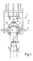
- a lifting unit 1 with a frame 2 drawn in the not shown Way is movable.
- a lifting clamp 3 around an essentially horizontal pivot axis 4 is pivotable stored.
- the lifting tongs can be parallel to Pivot axis 4, for example by cylinder units, be opened or closed.
- a stator laminated core 6 is fixed in the lifting tongs 3. Two Stator coils 7, 8 are not inserted in closer Pull-in slats of a pull-in tool 9 shown below the stator laminated core 6.
- a lid 10 is on Frame 2 of the lifting unit 1 along the axis 11 in the Lifting clamp 3 clamped stator laminated core 6 movable appropriate. He can thus in the direction of arrow P by the Stator laminated core 6 down to the Pulling tool 9 are placed.
- the patch position is marked with the reference number 10 '. In this Position of the cover 10 are the retractable needles Retracting tool 9 in the radial direction and with respect to it fixed uniform division along the circumference.
- the lifting unit 1 is also in the direction of arrow P lowerable so that the stator core 6 on the Retracting tool 9 can be placed. Then be the stator coils 7, 8 in the grooves, not shown of the stator core 6, where z. B. that Retracting tool 9 in a known manner from below in the Stator laminated core is pressed in.
- the lifting clamp 3 produces in this case the necessary counterforce, so that a so-called separate stator voltage can be omitted.
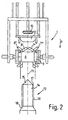
- stator coils 7, 8 are in the non-molded position as shown at 7 'and 8', respectively.
- An upper intermediate die 12 of one essentially conical shape serves the stator coils 7, 8 in the to bring intermediate position 7 '', 8 ''.
- the lifting unit 1 via a Intermediate molding station driven and the stator core 6 an intermediate mandrel 13 attached.
- the upper ends which according to the unshaped position 7 ', 8' in Are inclined in the direction of the axis 11, so far outwards pressed that the intermediate mold 12 from above can attack and the desired intermediate shape 7 '', 8 '' causes.
- the process of intermediate shaping is particularly based on Fig. 2 illustrates.
- the lifting unit 1 is for this purpose lower intermediate mandrel 13 driven.
- the mandrel 13 has a cylindrical surface 14 with a tip 15.
- the slats 16 are like this dimensioned that they are in empty, not yet with stator coils 7, 8 provided grooves of the stator core 6 can be. This happens when the lifting tongs 3 are lowered (Arrow P).
- the coil ends are not preformed stator coils 7 ', 8' over the tip 15 and the Drafts 17 pressed outwards.
- the intermediate one Form 7 '' or 8 '' is then on the lower form cone 18 and by lowering the upper intermediate mold 12, that forms an upper mold cone.
- the relative Position of the upper intermediate mold 12 relative to the cover 10 shows that the intermediate mold 12 is constructed in a ring is, so that the lid 10 along the axis 11 not only between the stator laminated core 6, but also through that Intermediate mold 12 is movable through.
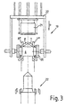
- Fig. 3 shows the stator core 6 in another Lifting unit 19 to which the stator core 6 has been handed over in the meantime. It is in one Lifting tongs 20, the design and pivotability of those corresponds to the lifting clamp 3.
- the lifting unit 19 is as Machining tool an upper end mold 21 in turn movably attached to the frame 22 of the lifting unit 19.
- the Lifting unit 19 is above a lower end mold 22 arranged.
- the final shaping of the coils 7, 8 into the final shape Position 7 '' ', 8' '' takes place by lowering the Stator laminated core 6 on the final forming tool 22 and then pressing on the upper end mold 22 instead of.
- FIG. 4 results from the depiction Procedure in connection with the complete Production line 23.
- Two lifting units 1, 19 are on one Portal 24, the legs 25, 26 at the bottom of a Factory hall is attached, in essentially horizontal Movable direction.
- the lifting unit 1 takes in the manner described a stator laminated core 6 at a loading station 27.
- the stator laminated core is initially horizontal Alignment 6a stored on a shelf 28.
- the tray 28 is easier to handle because that comparatively heavy stator laminated core does not have the Holding mandrel 29 must be lifted.
- the mandrel 29 will then mechanically inserted into the stator core 6a and pivoted about the pivot axis 30 so that the Lifting unit 1, the stator core 6 in the above essentially vertical alignment with its lifting tongs 3 can record.
- the pull-in station 31 also includes one Not shown winding unit for winding and Placing the stator coils 7, 8 in the drawing tool 9 Protective housing 32 which during this winding process around the Retracting tool 9 is arranged around this indicates this fact on.
- the Protective housing 32 removed from the pull-in tool 9. The Retraction then takes place in the on the basis of FIG. 1 described way.
- the lifting unit 1 will continue to move until it is in the position shown in Fig. 4 above the Intermediate molding station 33 is located.
- stator core 6 is on the Transfer station 34 stored in a defined position. Here it is lifted by the lifting unit 19, as mentioned above, also has a lifting clamp 3, recorded and for Forming station 35 brought. There is in the on the basis of Fig. 3 described the final shaping of the stator coils performed. Then the stator core 6 is on an unloading station 36 stored.
- the travel paths 37, 38 of the two lifting tongs 1, 19 are in the described embodiment thus just so set up that no collision can take place. she allow that both lifting units 1, 19 straight up to Transfer station 34 can be driven.
- Essential for this automation of manufacturing is the design of the lifting units 1, 19, in which the Stator laminated core 6 based on the lifting units 1, 19 integrated, movable processing tools 10, 12, 21 machining of the stator laminations 6 from the opposite side, d. H. is possible from above in the exemplary embodiment, during or after the stator laminations 6 by lowering the lifting units 1, 19 onto lower processing tools 9, 13, 22 can be lowered.
Landscapes
- Engineering & Computer Science (AREA)
- Manufacturing & Machinery (AREA)
- Power Engineering (AREA)
- Manufacture Of Motors, Generators (AREA)
Claims (13)
- Dispositif pour le montage de bobines dans des paquets de tôles de stator, comprenant un outil d'insertion (9), un couvercle (10) destiné à l'immobilisation d'aiguilles d'insertion (16) de l'outil d'insertion (9) et une monture (3) destinée à l'immobilisation du paquet de tôles de stator pendant l'insertion,
caractérisé en ce quele dispositif comprend une unité élévatrice (1) qui peut être déplacée entre au moins deux stations (27, 31, 33, 34, 35, 36) pour le chargement ou le déchargement pour le transfert et/ou le travail,la monture (3) est constituée par une pince élévatrice (3) destinée à saisir le paquet de tôles de stator (6) latéralement au niveau de sa périphérie et elle est disposée de façon mobile sur un châssis (2) de l'unité élévatrice (1), etl'unité élévatrice (1) comprend le couvercle (10) destiné à l'immobilisation des aiguilles d'insertion (16), le couvercle (10) étant mobile par rapport à la pince élévatrice (3). - Dispositif selon la revendication 1,
caractérisé en ce que le couvercle (10) peut se déplacer le long de l'axe médian (11) d'un paquet de tôles de stator (6) qui est tenu dans la pince élévatrice (3). - Dispositif selon l'une des revendications 1 ou 2 précitées,
caractérisé en ce qu'il est prévu un outil de travail constituant un outil de mise en forme (12) destiné à la mise en forme des bobines de stator (7, 8) sur le côté opposé du paquet de tôles de stator (6) qui est à l'opposé du côté d'insertion. - Dispositif selon l'une des revendications 1 à 3 précitées,
caractérisé en ce que la monture (3) peut pivoter par rapport au châssis (2) de l'unité élévatrice (1). - Dispositif selon l'une des revendications 1 à 4 précitées,
caractérisé en ce que l'unité élévatrice (1) peut se déplacer entre une station de chargement (27), une station d'insertion (31) et/ou une station de mise en forme (33). - Dispositif selon l'une des revendications 1 à 5 précitées,
caractérisé en ce qu'il est prévu au moins une unité élévatrice (19) supplémentaire comportant au moins un autre outil de travail. - Dispositif selon l'une des revendications 1 à 6 précitées,
caractérisé en ce l'unité élévatrice (19) supplémentaire présente un outil de mise en forme finale (21) et peut être amenée à une station de mise en forme finale (35). - Procédé pour le montage de bobines dans des paquets de tôles de stator avec un outil d'insertion (9), un couvercle (10) destiné à l'immobilisation d'aiguilles d'insertion (16) de l'outil d'insertion (9) et une monture (3) destinée à l'immobilisation d'un paquet de tôles de stator (6) pendant l'insertion,
caractérisé en ce que le paquet de tôles de stator (6) est saisi latéralement au niveau de sa périphérie au moyen d'une monture constituée par une pince élévatrice (3) et en ce que le paquet de tôles de stator (6) est travaillé au moyen d'une unité élévatrice (1) pouvant se déplacer et comprenant la pince élévatrice (3), dans une station d'insertion (31) et une station de mise en forme (33) sans transférer le paquet de tôles de stator (6) de la pince élévatrice (3) à la station de travail (31, 33) concernée. - Procédé selon la revendication 8,
caractérisé en ce que le paquet de tôles de stator est saisi par une unité élévatrice (1) dans une station de chargement (27), élevé et amené à une station d'insertion (31), le couvercle (10) étant transporté dans une direction axiale à travers le paquet de tôles de stator (6) et appliqué sur l'outil d'insertion (9). - Procédé selon la revendication 8 ou 9,
caractérisé en ce que la force antagoniste exercée lors de l'insertion des bobines ou du groupe de bobines à travers l'outil d'insertion (9) est développée par la pince élévatrice (3) de l'unité élévatrice (1). - Procédé selon l'une des revendications 9 à 11,
caractérisé en ce que le paquet de tôles de stator (6), avec l'unité élévatrice (1), est transporté de la station d'insertion (31) à une station de mise en forme (33), et l'unité élévatrice (1) emboíte le paquet de tôles de stator (6) sur un outil de mise en forme (13) par une translation de la pince élévatrice (3), les bobines de stator (7, 8) étant mises en forme sur le côté opposé, au moyen d'un outil de mise en forme (12) fixé de façon mobile en translation à l'unité élévatrice (1). - Procédé selon l'une des revendications 8 à 11,
caractérisé en ce que, dans une station de transfert (34), le paquet de tôles de stator (6) est transféré à au moins une unité élévatrice (19) supplémentaire. - Procédé selon l'une des revendications 8 à 12,
caractérisé en ce que, lors du montage des bobines, il se produit une mise en forme intermédiaire et une mise en forme finale des bobines de stator (7, 8) dans au moins deux stations de mise en forme (33, 35) différentes.
Applications Claiming Priority (3)
| Application Number | Priority Date | Filing Date | Title |
|---|---|---|---|
| DE19815088 | 1998-04-06 | ||
| DE19815088A DE19815088A1 (de) | 1998-04-06 | 1998-04-06 | Vorrichtung zur Herstellung von Spulenwicklungen in Statorblechpaketen |
| US09/288,103 US6401326B1 (en) | 1998-04-06 | 1999-04-08 | Device for producing coil windings in stator laminated cores |
Publications (3)
| Publication Number | Publication Date |
|---|---|
| EP0949746A2 EP0949746A2 (fr) | 1999-10-13 |
| EP0949746A3 EP0949746A3 (fr) | 2000-08-30 |
| EP0949746B1 true EP0949746B1 (fr) | 2004-08-11 |
Family
ID=26045269
Family Applications (1)
| Application Number | Title | Priority Date | Filing Date |
|---|---|---|---|
| EP99106517A Expired - Lifetime EP0949746B1 (fr) | 1998-04-06 | 1999-03-30 | Dispositif pour fabriquer des enroulements dans des empilages de tôles statoriques |
Country Status (4)
| Country | Link |
|---|---|
| US (1) | US6401326B1 (fr) |
| EP (1) | EP0949746B1 (fr) |
| JP (1) | JPH11318060A (fr) |
| DE (1) | DE19815088A1 (fr) |
Families Citing this family (12)
| Publication number | Priority date | Publication date | Assignee | Title |
|---|---|---|---|---|
| JP3445953B2 (ja) * | 2000-02-24 | 2003-09-16 | ファナック株式会社 | 固定子巻線のコイルインサータ |
| JP4923545B2 (ja) * | 2005-12-02 | 2012-04-25 | 株式会社デンソー | 回転電機 |
| US9130439B2 (en) * | 2013-04-16 | 2015-09-08 | Remy Technologies, L.L.C. | Method of flaring stator windings |
| CN105680641B (zh) * | 2016-03-26 | 2017-12-29 | 舟山晨光电器有限公司 | 电机定子的组装机 |
| JP2018042373A (ja) * | 2016-09-07 | 2018-03-15 | 日本電産株式会社 | 位置決め治具および位置決め方法 |
| JP2018042374A (ja) * | 2016-09-07 | 2018-03-15 | 日本電産株式会社 | 導通部材固定装置および導通部材固定方法 |
| DE102016013777A1 (de) | 2016-11-18 | 2018-04-12 | Audi Ag | Vorrichtung und Verfahren zum Transportieren einer Komponente |
| US11418095B2 (en) * | 2017-08-25 | 2022-08-16 | Mitsubishi Heavy Industries Engine & Turbocharger, Ltd. | Motor assembling method, centering jig, and electric motor |
| DE102018100016A1 (de) * | 2018-01-02 | 2019-07-04 | Elmotec Statomat Holding GmbH | Verfahren und Vorrichtung zur Herstellung von Rotoren und Statoren einschließlich der Konfektionierung von Anschlussdrähten |
| EP3624314A1 (fr) * | 2018-09-17 | 2020-03-18 | Siemens Aktiengesellschaft | Insertion d'enroulements dans un paquet de tôles de stator |
| DE102019209272A1 (de) | 2019-06-26 | 2020-12-31 | Magna powertrain gmbh & co kg | Verfahren und eine Vorrichtung zum Einziehen von Spulen |
| CN110635637B (zh) * | 2019-09-25 | 2021-11-12 | 株洲南方机电制造有限公司 | 一种包带头的升降方法及升降装置 |
Family Cites Families (13)
| Publication number | Priority date | Publication date | Assignee | Title |
|---|---|---|---|---|
| DE2630183C3 (de) * | 1976-07-05 | 1986-07-31 | Otto 7980 Ravensburg Rist | Vorrichtung zum Einziehen von Wicklungen in Nuten von Statoren von Elektromotoren |
| US4106189A (en) * | 1977-02-28 | 1978-08-15 | Peters Robert W | Stator coil press |
| US4265012A (en) * | 1979-02-23 | 1981-05-05 | Balzer & Droll Kg | Device for collecting windings in stators or the like |
| DE3114407A1 (de) * | 1981-04-09 | 1982-11-11 | Balzer & Dröll GmbH, 6369 Niederdorfelden | Verfahren und vorrichtung zum wickeln und einziehen von spulen in nuten von stator- und rotorblechpaketen elektrischer maschinen |
| US4416058A (en) * | 1981-12-17 | 1983-11-22 | Essex Group Incorporated | Apparatus for winding coils and inserting coils and wedges into stator cores |
| US4476625A (en) * | 1982-09-30 | 1984-10-16 | Pease Machine & Tool, Inc. | Apparatus of inserting wedges into the slots of a magnetic core |
| JPS6020760A (ja) * | 1983-07-13 | 1985-02-02 | Hitachi Ltd | 電動機のコイル插入装置 |
| EP0191195B1 (fr) * | 1985-02-15 | 1989-08-02 | Micafil Ag | Dispositif pour la fabrication automatique de stators pour moteurs électriques |
| SU1415337A1 (ru) * | 1986-09-04 | 1988-08-07 | Специальное проектно-конструкторское и технологическое бюро по погружному электрооборудованию для бурения скважин и добычи нефти Всесоюзного научно-производственного объединения "Потенциал" | Полуавтомат дл сборки сердечников электрических машин |
| DE3735870A1 (de) * | 1987-10-07 | 1989-04-27 | Statomat Globe Maschf | Verfahren und vorrichtung zur abnahme von blechen von einem stapel |
| JP3201047B2 (ja) * | 1993-01-28 | 2001-08-20 | 安藤電気株式会社 | プリント基板へのプレスフィットコネクタ圧入装置 |
| CA2140569A1 (fr) * | 1994-01-27 | 1995-07-28 | Giuseppe Cardini | Methode et appareil de fabrication de stators |
| US5517750A (en) * | 1994-07-18 | 1996-05-21 | Submersible Pumps, Inc. | Apparatus for salvaging core laminations |
-
1998
- 1998-04-06 DE DE19815088A patent/DE19815088A1/de not_active Withdrawn
-
1999
- 1999-03-30 EP EP99106517A patent/EP0949746B1/fr not_active Expired - Lifetime
- 1999-04-05 JP JP11097712A patent/JPH11318060A/ja active Pending
- 1999-04-08 US US09/288,103 patent/US6401326B1/en not_active Expired - Fee Related
Also Published As
| Publication number | Publication date |
|---|---|
| EP0949746A2 (fr) | 1999-10-13 |
| JPH11318060A (ja) | 1999-11-16 |
| DE19815088A1 (de) | 1999-10-07 |
| EP0949746A3 (fr) | 2000-08-30 |
| US6401326B1 (en) | 2002-06-11 |
Similar Documents
| Publication | Publication Date | Title |
|---|---|---|
| DE4301234B4 (de) | Verfahren und Einrichtung zum Herstellen von Ankern für elektrodynamische Maschinen | |
| EP0949746B1 (fr) | Dispositif pour fabriquer des enroulements dans des empilages de tôles statoriques | |
| WO2018233774A1 (fr) | Dispositif et procédé servant à fabriquer un élément de machine pourvu d'enroulements pour une machine électrique | |
| EP3735737B1 (fr) | Procédé et dispositif de fabrication de rotors et de stators, incluant la confection de fils de connexion | |
| DE2001677B2 (de) | Vorrichtung zum Einziehen von Spulen in die Nuten eines Stators elektrischer Maschinen | |
| DE3227871A1 (de) | Verfahren und vorrichtung zum einlegen von wicklungen in die schlitze eines statorkernes einer elektrischen maschine | |
| DE2630183A1 (de) | Verfahren zum einziehen von wicklungen in nuten von statorpaketen und ankern und vorrichtung zur ausuebung des verfahrens | |
| DE2313417C3 (de) | Vorrichtung zum Herstellen von verdrallten Leitungsdrahtpaaren und Verfahren zum Verdrallen von Leitungsdrahtpaaren | |
| DE3027457C2 (de) | Verfahren und Vorrichtungen zum Einziehen von Wicklungen in Statornuten | |
| DE3337040C2 (fr) | ||
| DE3000896C2 (de) | Statorspulenwickel- und -einziehmaschine | |
| DE3348055C2 (fr) | ||
| DE69409980T2 (de) | Automatische Spulenwickelmaschine | |
| DE102016219480A1 (de) | Montagevorrichtung zum gleichzeitigen Einführen von Kupferstäben | |
| DE19633155A1 (de) | Einrichtungen und Verfahren zum Einziehen von Statorwicklungs-Spulengruppen in einen Statorkern | |
| DE2825557C2 (fr) | ||
| DE102016113686A1 (de) | Ziehschlitten für eine Ziehmaschine | |
| DE3409684C1 (de) | Verfahren,Einziehwerkzeug,Einziehnadel und Fixierstern zum Einziehen von Spulen in Statoren von Elektromotoren | |
| DE3812726A1 (de) | Vorrichtung zum einziehen von spulen in statoren von elektromotoren | |
| DE69107658T3 (de) | Verfahren und Gerät zur Einführung von Statorwicklungsadern in Drahtaufnahmekanäle aufweisende Verbinder. | |
| DE2821709C2 (de) | Vorrichtung zum Abbau und Wiederzusammenbau eines aus mehreren Segmenten bestehenden Laufflächenringes | |
| DE3343390C2 (de) | Verfahren zum Herstellen von Wellenwicklungen und Vorrichtung zum Durchführen dieses Verfahrens | |
| DE3880461T2 (de) | Verfahren und Vorrichtung zum Wechseln des Schreibwerkzeuges in einer Zeichenmaschine. | |
| DE2751264A1 (de) | Vorrichtung zur erleichterung der abnahme voller spulen von spindelbaenken | |
| EP0963031A2 (fr) | Procédé et appareil pour l'insertion de bobines pour la fabrication d'un stator de machine électrique |
Legal Events
| Date | Code | Title | Description |
|---|---|---|---|
| PUAI | Public reference made under article 153(3) epc to a published international application that has entered the european phase |
Free format text: ORIGINAL CODE: 0009012 |
|
| AK | Designated contracting states |
Kind code of ref document: A2 Designated state(s): AT CH DE FR GB IT LI |
|
| AX | Request for extension of the european patent |
Free format text: AL;LT;LV;MK;RO;SI |
|
| PUAL | Search report despatched |
Free format text: ORIGINAL CODE: 0009013 |
|
| AK | Designated contracting states |
Kind code of ref document: A3 Designated state(s): AT BE CH CY DE DK ES FI FR GB GR IE IT LI LU MC NL PT SE |
|
| AX | Request for extension of the european patent |
Free format text: AL;LT;LV;MK;RO;SI |
|
| 17P | Request for examination filed |
Effective date: 20001130 |
|
| AKX | Designation fees paid |
Free format text: AT CH DE FR GB IT LI |
|
| 17Q | First examination report despatched |
Effective date: 20020814 |
|
| GRAP | Despatch of communication of intention to grant a patent |
Free format text: ORIGINAL CODE: EPIDOSNIGR1 |
|
| GRAS | Grant fee paid |
Free format text: ORIGINAL CODE: EPIDOSNIGR3 |
|
| GRAA | (expected) grant |
Free format text: ORIGINAL CODE: 0009210 |
|
| AK | Designated contracting states |
Kind code of ref document: B1 Designated state(s): AT CH DE FR GB IT LI |
|
| REG | Reference to a national code |
Ref country code: GB Ref legal event code: FG4D Free format text: NOT ENGLISH |
|
| REG | Reference to a national code |
Ref country code: CH Ref legal event code: EP |
|
| GBT | Gb: translation of ep patent filed (gb section 77(6)(a)/1977) |
Effective date: 20040811 |
|
| REF | Corresponds to: |
Ref document number: 59910162 Country of ref document: DE Date of ref document: 20040916 Kind code of ref document: P |
|
| REG | Reference to a national code |
Ref country code: CH Ref legal event code: NV Representative=s name: KELLER & PARTNER PATENTANWAELTE AG |
|
| ET | Fr: translation filed | ||
| PLBE | No opposition filed within time limit |
Free format text: ORIGINAL CODE: 0009261 |
|
| STAA | Information on the status of an ep patent application or granted ep patent |
Free format text: STATUS: NO OPPOSITION FILED WITHIN TIME LIMIT |
|
| 26N | No opposition filed |
Effective date: 20050512 |
|
| PGFP | Annual fee paid to national office [announced via postgrant information from national office to epo] |
Ref country code: AT Payment date: 20070313 Year of fee payment: 9 |
|
| PGFP | Annual fee paid to national office [announced via postgrant information from national office to epo] |
Ref country code: CH Payment date: 20070315 Year of fee payment: 9 |
|
| PGFP | Annual fee paid to national office [announced via postgrant information from national office to epo] |
Ref country code: FR Payment date: 20070321 Year of fee payment: 9 |
|
| PGFP | Annual fee paid to national office [announced via postgrant information from national office to epo] |
Ref country code: IT Payment date: 20080326 Year of fee payment: 10 Ref country code: GB Payment date: 20080320 Year of fee payment: 10 |
|
| REG | Reference to a national code |
Ref country code: CH Ref legal event code: PL |
|
| PG25 | Lapsed in a contracting state [announced via postgrant information from national office to epo] |
Ref country code: AT Free format text: LAPSE BECAUSE OF NON-PAYMENT OF DUE FEES Effective date: 20080330 |
|
| REG | Reference to a national code |
Ref country code: FR Ref legal event code: ST Effective date: 20081125 |
|
| PG25 | Lapsed in a contracting state [announced via postgrant information from national office to epo] |
Ref country code: LI Free format text: LAPSE BECAUSE OF NON-PAYMENT OF DUE FEES Effective date: 20080331 Ref country code: CH Free format text: LAPSE BECAUSE OF NON-PAYMENT OF DUE FEES Effective date: 20080331 |
|
| PG25 | Lapsed in a contracting state [announced via postgrant information from national office to epo] |
Ref country code: FR Free format text: LAPSE BECAUSE OF NON-PAYMENT OF DUE FEES Effective date: 20080331 |
|
| GBPC | Gb: european patent ceased through non-payment of renewal fee |
Effective date: 20090330 |
|
| PG25 | Lapsed in a contracting state [announced via postgrant information from national office to epo] |
Ref country code: GB Free format text: LAPSE BECAUSE OF NON-PAYMENT OF DUE FEES Effective date: 20090330 |
|
| PGFP | Annual fee paid to national office [announced via postgrant information from national office to epo] |
Ref country code: DE Payment date: 20100409 Year of fee payment: 12 |
|
| PG25 | Lapsed in a contracting state [announced via postgrant information from national office to epo] |
Ref country code: IT Free format text: LAPSE BECAUSE OF NON-PAYMENT OF DUE FEES Effective date: 20090330 |
|
| PG25 | Lapsed in a contracting state [announced via postgrant information from national office to epo] |
Ref country code: DE Free format text: LAPSE BECAUSE OF NON-PAYMENT OF DUE FEES Effective date: 20111001 |
|
| REG | Reference to a national code |
Ref country code: DE Ref legal event code: R119 Ref document number: 59910162 Country of ref document: DE Effective date: 20111001 |