EP0949766B1 - Mehrbenutzerempfangsgerät mit paralleler Störunterdrückung - Google Patents
Mehrbenutzerempfangsgerät mit paralleler Störunterdrückung Download PDFInfo
- Publication number
- EP0949766B1 EP0949766B1 EP19990106756 EP99106756A EP0949766B1 EP 0949766 B1 EP0949766 B1 EP 0949766B1 EP 19990106756 EP19990106756 EP 19990106756 EP 99106756 A EP99106756 A EP 99106756A EP 0949766 B1 EP0949766 B1 EP 0949766B1
- Authority
- EP
- European Patent Office
- Prior art keywords
- user
- signal
- stage
- interference
- symbol
- Prior art date
- Legal status (The legal status is an assumption and is not a legal conclusion. Google has not performed a legal analysis and makes no representation as to the accuracy of the status listed.)
- Expired - Lifetime
Links
- 238000000034 method Methods 0.000 claims description 84
- 230000008569 process Effects 0.000 claims description 59
- 230000005540 biological transmission Effects 0.000 claims description 13
- 230000007480 spreading Effects 0.000 claims description 12
- 238000004891 communication Methods 0.000 claims description 9
- 238000012545 processing Methods 0.000 claims description 5
- 230000003111 delayed effect Effects 0.000 claims description 4
- 238000001427 incoherent neutron scattering Methods 0.000 claims 7
- 238000010586 diagram Methods 0.000 description 10
- 230000006866 deterioration Effects 0.000 description 4
- 230000000694 effects Effects 0.000 description 4
- 230000003044 adaptive effect Effects 0.000 description 2
- 238000007792 addition Methods 0.000 description 1
- 230000000593 degrading effect Effects 0.000 description 1
- 238000001514 detection method Methods 0.000 description 1
- 230000002542 deteriorative effect Effects 0.000 description 1
- 238000011161 development Methods 0.000 description 1
- 230000018109 developmental process Effects 0.000 description 1
- 238000010295 mobile communication Methods 0.000 description 1
- 230000004048 modification Effects 0.000 description 1
- 238000012986 modification Methods 0.000 description 1
- 230000009467 reduction Effects 0.000 description 1
Images



Classifications
-
- H—ELECTRICITY
- H04—ELECTRIC COMMUNICATION TECHNIQUE
- H04B—TRANSMISSION
- H04B1/00—Details of transmission systems, not covered by a single one of groups H04B3/00 - H04B13/00; Details of transmission systems not characterised by the medium used for transmission
- H04B1/69—Spread spectrum techniques
- H04B1/707—Spread spectrum techniques using direct sequence modulation
- H04B1/7097—Interference-related aspects
- H04B1/7103—Interference-related aspects the interference being multiple access interference
- H04B1/7107—Subtractive interference cancellation
- H04B1/71075—Parallel interference cancellation
Definitions
- the present invention relates to a CDMA (Code Division Multiple Access) multi-user receiving apparatus for performing an interference canceling process in parallel for individual users on a plurality of stages and for outputting demodulated signals for the individual users on the last stage, in particular, to a multi-user receiving apparatus with excellent interference cancellation characteristics in a small hardware scale.
- CDMA Code Division Multiple Access
- DS-CDMA system CDMA system using direct sequence (DS) spreading process
- DS-CDMA system CDMA system using direct sequence (DS) spreading process
- each user signal is spreaded in a wide frequency band with particular code and transmitted to a propagation path.
- the code-multiplexed signal is de-spreaded and a desired signal is detected.
- spreaded codes assigned to individual users correlate, they interfere and the reception characteristics deteriorate.
- the first stage circuit demodulates all user signals, generates interference replicas of the user signals, and subtracts interference replicas other than an interface replica for a desired user signal from the received signal.
- the next stage circuit demodulates the desired user signal with the output signal of the first stage circuit.
- the demodulated result of the second stage circuit is improved in comparison with the demodulated result of the first stage circuit.
- the interference canceling process is repeated a plurality of times and thereby the interference cancellation characteristics are improved.
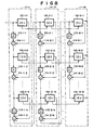
- Fig. 8 is a block diagram showing an example of the structure of a CDMA multi-user receiving apparatus disclosed by Yoshida et. al as Japanese Patent Laid-Open Publication No. 10-51353.
- the apparatus has a plurality of IEUs 112-m-n disposed on a plurality of stages. IEUs 112-m-n disposed on each stage correspond to individual user signals. An IEU 112-m-n that corresponds to the highest hierarchical level user signal performs an interference canceling process for the lowest hierarchical level user signal on the preceding (m - 1)-th stage.
- An IEU 112-m-n that corresponds to other than the highest hierarchical level user signal performs an interference canceling process for the (n - 1)-th hierarchical level user signal.
- An IEU 112-m-n inputs an error signal obtained in the interference canceling process and an interference replica estimated by the IEU 112-(m - 1)-n corresponding to the same hierarchical level user signal on the preceding stage, re-estimates the current m-th stage interference replica, outputs the re-estimated interference replica to an IEU 112-(m + 1)-n corresponding to the same hierarchical level user signal on the next (m + 1)-th stage, and outputs the result of the diffusing process as the difference between an interference replica on the current m-th stage and an interference replica on the preceding (m - 1)-th stage.
- IEU 112-M-1, ..., IEU 112-M-N on the last M-th stage output demodulated results as demodulated user signals rather than re-estimating interference replicas on the current M
- the interference canceling process is performed by M column x N line circuits (where M represents the number of stages; and N represents the number of user signals). Reception levels of individual user signals are pre-assigned. Each user signal is connected to each stage in series corresponding to a reception level. A demodulating process and an interpolation canceling process are performed for user signals in the order from the highest signal level to the lowest signal level. In this structure, since the interference canceling process is performed in series, interference replicas can be sequentially canceled. Thus, although excellent interference cancellation characteristics are accomplished, the circuit structure is complicated and a delay in the demodulating process is large.
- Fig. 9 is a block diagram showing another example of the structure of a CDMA multi-user receiving apparatus.
- the interference canceling process is a simple parallel structure apparatus.
- the receiving apparatus has multiplying units disposed on the output side of interference estimating units IEU. Each multiplying unit multiplies an output signal of the interference estimating unit by a weighting coefficient ⁇ that is 1 or smaller. Thus, the interference cancellation characteristics are improved.
- a first stage interference canceling process circuit 101-1 comprises a delaying unit 103-1, interference estimating units (IEU) 102-1-1 to 102-1-N, multiplying units 105-1-1 to 105-1-N, and a subtracting unit 104-1.
- the multiplying units 105-1-1 to 105-1-N multiply output signals of the interference estimating units 102-1-1 to 102-1-N by a weighting coefficient ⁇ , respectively.
- the subtracting unit 104-1 subtracts output signals of the multiplying units 105-1-1 to 105-1-N from an output signal of the delaying unit 103-1.
- An interference estimating unit (IEU) 102-m-n on the m-th stage (where m is any integer of 1 ⁇ m ⁇ M) for the n-th user signal (where n is any integer of 1 ⁇ n ⁇ N) inputs an interference cancellation residual signal (an output signal of a subtracting unit 104-(m - 1)) obtained in the interference canceling process on the (m - 1)-th stage and a symbol replica (a replica that is output from an IEU 102-(m - 1)-n) corresponding to the same user signal on the (m - 1)-th stage, generates an m-th stage symbol replica, outputs the generated symbol replica to the (m + 1)-th stage, and outputs a spreaded signal that is the difference between the m-th stage symbol replica and an (m - 1)-th stage symbol replica.
- a multiplying unit 105-m-n multiplies the output signal of the interference estimating unit 102-m-n by the weighting coefficient ⁇ .
- a subtracting unit 104-m subtracts the output signals of the multiplying units 105-m-n for all user signals from a signal of which the (m - 1)-th stage interference cancellation residual signal is delayed by a delaying unit 103-m for the IEU process, updates the interference cancellation residual signal, and outputs the resultant signal to the (m + 1)-th stage.
- Fig. 2 is a block diagram showing the structure of the interference estimating unit (IEU) 102-m-n.
- the IEU 102-m-n has a plurality of path processing portions (#1 to #K) corresponding to a plurality of propagation paths as a multi-path.
- An inversely spreading means 11 inputs an (m - 1)-th stage interference cancellation residual signal (an output signal of a subtracting unit 104-(m - 1)).
- the despreading means 11 performs an despreading process for a signal corresponding to the each path.
- a first adding unit 12 adds an output signal of the despreading means 11 and an (m - 1)-th stage symbol replica (a replica that is output from an IEU 102-(m - 1)-n).
- a detecting unit 13 inputs an output signal of the first adding unit 12.
- a propagation path estimating means 20 detects a propagation path estimation value corresponding to the each path.
- a complex conjugate means 21 outputs a complex conjugate value to a multiplying unit 22.
- the multiplying unit 22 multiplies the complex conjugate value by the output signal of the first adding unit 12 so as to demodulate the signal corresponding to the each path.
- a second adding unit 14 adds output signals of the detecting units 13 corresponding to the individual paths (#1 to #K).
- a decision unit 15 determines a symbol of an output signal of the second adding unit 14.
- a multiplying unit 16 multiplies an output signal of the decision unit 15 by the propagation path estimation value that is output from the propagation path estimating means 20 corresponding to the each path of the paths (#1 to #K) and generates a symbol replica corresponding to the each path.
- a subtracting unit 17 subtracts an (m - 1)-th stage symbol replica from an m-th stage symbol replica.
- a spreading means 18 spreads an output signal of the subtracting unit 17 corresponding to the current(each) path.
- a third adding unit 19 adds outputs signals of the spreading means 18 corresponding to the individual paths #1 to #K.
- a reception signal as an interference cancellation residual signal obtained in an (m - 1)-th stage interference canceling process is used.
- zero as a symbol replica corresponding to the same user signal on the (m - 1)-th stage is used.
- the interference canceling process is not performed.
- spread signals as the difference between m-th stage replicas and (m - 1)-th stage replicas are output. Instead, demodulated signals are output.
- the characteristics of a parallel process structure interference canceler are inferior to the characteristics of a serial process structure interference canceler. This is because in the serial structure, the interference canceling process can be performed between user signals on each stage. On the other hand, in the parallel process, the interference canceling process can be sequentially performed.
- the interference canceling process When the interference canceling process is performed for user signals in the order of the largest signal levels, the characteristics are further improved.
- an output signal of each IEU 102-M-N is multiplies by a real number ⁇ that is 1 or smaller so as to improve the characteristics of the parallel process.
- the real number ⁇ alleviates the interference canceling process.
- all interferences are not canceled on the first stage. Instead, the interferences are gradually canceled on a plurality of stages.
- the interference canceling process is alleviated on the first stage that has a large propagation path estimation error and a large determined symbol error.
- the interference cancellation error is suppressed.
- the interference canceling performance is shared with downstream stages that have a small propagation path estimation error and a small determined symbol determined symbol error. Consequently, the interference cancellation characteristics can be improved.
- BP-A-823796 discloses a multi-user receiving apparatus for inputting a CDMA reception signal performing an interference canceling process in parallel for each user signal on an m-th stage of M stages (11-1,...,11-M), whereby m is any integer between 1 and M; and M is any integer that is 2 or larger, and outputting demodulated signals on the M-th stage. It comprises a plurality of interference estimating units (IEUs) (12-m-n) disposed corresponding to the M stages and the number of user signals, a plurality of subtracting units (14-1,..., 14-M) disposed corresponding to the (M-1) stages and first multiplying units (30) for multiplying the output signals of the IEUs by a first weighting coefficient ( ⁇ ).
- IEUs interference estimating units
- Each of the subtracting units (14-1,...,14-M) subtracts signals weighted by the first multiplying units (30) from the spread signals outputted from the IEUs on the m-th stage with a second weighting coefficient, from a signal delayed by a delay unit (13-1,...,13-M) and by a predetermined value of the (m-1)-th stage interference cancellation residual signal and outputs the resultant signal to the (m + 1)-th stage.
- An object of the present invention is to provide a multi-user receiving apparatus that has interference cancellation characteristics similar to those of a serial structure interference canceler and that has a small hardware scale suitable for a base station and a mobile station of a DS-CDMA communication system.
- the multi-user receiving apparatus is used for a base station or a mobile station.
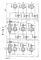
- Fig. 1 is a block diagram showing the structure of a multi-user receiving apparatus according to a first embodiment of the present invention.
- the multi-user receiving apparatus comprises M receiving units 1-1, ... , and 1-M on M stages (where M is any integer that is 2 or larger).
- a receiving unit 1-m (where 1 ⁇ m ⁇ M) on each stage comprises N interference estimating units (referred to as IEU) 2-m-n, a delaying unit 3-m, an adding unit 4-m, a first multiplying unit 6-m-n, and a second multiplying unit 5-m-n.
- the N IEUs 2-m-n receive N user signals (where N is any integer that is 1 or larger).
- the n interference estimating units (IEU) 2-m-n for n user signals (where n is any integer of 1 ⁇ n ⁇ N) on the m-th stage (where m is any integer of 1 ⁇ m ⁇ M) input an interference cancellation residual signal (an output signal of an adding unit 4-(m - 1)) obtained in the interference canceling process on the (m - 1)-th stage and signals of which symbol replicas corresponding to the same user signals on the (m - 1)-th stage are weighted with a first weight coefficient by first multiplying units 6-m-n, generates m-th stage symbol replicas, output the generated symbol replicas to the (m + 1)-th stage, and output spread signals that are the difference between the m-th stage symbol replicas and (m - 1)-th stage symbol replicas.
- IEU interference estimating units
- the second multiplying units 5-m-n multiply the output signals of the IEUs 2-m-n by a second weighting coefficient.
- the subtracting unit 4m subtracts the output signals of the multiplying units 5-m-n for all the user signals from a signal of which the (m - 1)-th stage interference cancellation residual signal is delayed for the process period of the IEUs by the delaying unit 3-m, updates the interference cancellation residual signal, and outputs the resultant signal to the (m + 1)-th stage.
- the structure of the interference estimating unit (IEU) 2-m-n is the same as that of the conventional IEU shown in Fig. 2.
- each IEU 2-m-m has a plurality of path processing portions corresponding to a plurality of paths as a multi-path.
- An despreading means 11 corresponding to each path inputs an (m - 1)-th stage interference cancellation residual signal and inversely spreads the interference cancellation residual signal.
- a first adding unit 12 adds an output signal of the despreading means 11 and an (m - 1)-th stage symbol replica corresponding to the current path.
- a detecting unit 13 inputs an output signal of the first adding unit 12.
- a complex conjugate means 21 converts a propagation path estimation value received from a propagation path estimating means 20 into a complex conjugate corresponding to the current path.
- a multiplying unit 22 multiplies the complex conjugate by the output signal of the first adding unit so as to demodulate the signal corresponding to the current path.
- a second adding unit 14 adds output signals of the detecting units 13 corresponding to the individual paths. Thus, a path diversity effect can be obtained.
- a decision unit 15 determines a symbol of the output signal of the second adding unit 14. In QPSK modulation, the decision unit 15 determines Ich level and Qch level of an orthogonal signal as (1/ ⁇ 2, 1/ ⁇ 2), (-1/ ⁇ 2, 1/ ⁇ 2), (-1/ ⁇ 2, -1/ ⁇ 2), and (1/ ⁇ 2, -1/ ⁇ 2) corresponding to the first quadrant, the second quadrant, the third quadrant, and the fourth quadrant, respectively.
- a multiplying unit 16 multiplies the output signal of the decision unit 15 by a propagation path estimation value corresponding to the current path and generates an m-th stage symbol replica.
- a subtracting unit 17 subtracts the (m - 1)-th stage symbol replica from the m-th stage symbol replica.
- a spreading means 18 spreads the output signal of the subtracting unit 17.
- a third adding unit 19 adds the output signals of the spreading means 18 corresponding to the individual paths.
- a signal received from an antenna is used as an interference cancellation residual signal obtained in the interference canceling process on the (m - 1)-th stage.
- zero is used as a symbol replica for the same user signal on the (m - 1)-th stage.
- the interference canceling process is not performed.
- spread signals that are the difference between the m-th stage replicas and the (m - 1)th stage replicas are not output. Instead, demodulated signals corresponding to the individual paths are output.
- the second multiplying units 5-m-n are disposed on the output side of the IEUs 2-m-n.
- the second multiplying units 5-m-n may be disposed on the output side of the subtracting units 17 or the spreading means 18 of the IEUs 2-m-n.
- the first multiplying units 6-m-n that weight a first weighting coefficient are disposed.
- the weighting process is performed so as to gradually cancel interferences on a plurality of stages.
- the interference canceling process is alleviated on the first stage that has a large propagation path estimation error and a large determined symbol error.
- the interference cancellation error is suppressed.
- the interference canceling performance is shared with downstream stages that have a small propagation path estimation error and a small determined symbol error. Consequently, the interference cancellation characteristics can be improved.
- ⁇ 1 or smaller, if m is sufficiently large, e m converges to zero.
- the interferences can be completely canceled.
- the interference canceling process should be gradually performed.
- ⁇ should be small.
- the first and second weighting coefficients on the m-th stage are [1 - (1 - ⁇ ) m-1 , ⁇ ].
- the first and second weighting coefficients (1, ⁇ ) or ( ⁇ , ⁇ ) are used.
- the characteristics relatively deteriorate.
- a major cause of the deterioration of the parallel process structure interference canceler is a propagation path estimation error on the first stage.
- the propagation path estimating error depends on the ratio of signal power to interference power of each user signal.
- the value of ⁇ is assigned so that it is proportional to the ratio of signal power to interference power of each user signal.
- the transmission power is controlled.
- the ratio of signal power to interference power of each user signal is equally controlled.
- the ratio is reversely proportional to the number of user signals.
- the value of ⁇ is assigned so that it is reversely proportional to the number of user signals.
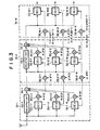
- Fig. 3 is a block diagram showing the structure of a multi-user receiving apparatus according to a second embodiment of the present invention.
- the structure of the multi-user receiving apparatus according to the second embodiment is almost the same as the structure of the multi-user receiving apparatus according to the first embodiment except that a first weighting coefficient of first multiplying units 36-m-n and a second weighting coefficient of second multiplying units 35-m-n of the second embodiment are different from those according to the first embodiment.
- the first and second weighting coefficients of the first and second multiplying units are [1 - (1 - ⁇ n1 )(1 - ⁇ n2 ) ... (1 - ⁇ nm-1 ), ⁇ nm ].
- the value of ⁇ is the same as that of the first embodiment shown in Fig. 1.
- the value of ⁇ nm depends on each stage and each user signal.
- the value of ⁇ nm is an adaptive value that chronologically varies.
- the first weighting coefficient is a product of a constant weighting coefficient ⁇ and an adaptive weighting coefficient ⁇ mn.
- the weighting process can be flexibly performed.
- the interference canceling process is gradually performed so as to suppress the characteristics from deteriorating.
- the interferences are canceled on downstream stages.
- a ⁇ nm determining method When the transmission power is ideally controlled, the ratio of signal power to interference power for each user signal is equally controlled. However, actually, a transmission power control error exists.
- Figs. 4A to 4C are graphs showing received signal powers of individual user signals in the case that a transmission power control error exists. Since the transmission power is controlled slot by slot, the received signal power varies slot by slot. Since the transmission power control error depends on each user signal, the ratio of signal power to interference power at each slot varies for each user signal.
- Figs. 4A to 4C show the state that the received signal power of each user signal #1 to #N varies against an average signal power slot by' slot.
- the value of ⁇ nm is assigned so that it is proportional to the ratio of signal power to interference power of each slot.
- each slot signal power of each user may be normalized with the average signal power.
- ⁇ nm determining method an interference cancellation error due to a determination symbol error can be suppressed.
- a determination symbol error results in a large interference cancellation error. For example, when a symbol error takes place in BPSK, a symbol interference that is 6 dB higher than the original symbol occurs rather than canceling interference.
- the likelihood of a determination symbol is estimated with a pre-determined reception symbol that has been normalized with an average signal power.
- a small value is assigned to ⁇ nm .
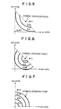
- Fig. 5 is a graph showing an example of a ⁇ nm determining method corresponding to the likelihood.
- Fig. 5 coordinates of Ich level and Qch level of an orthogonal signal are illustrated.
- the relation between a reception symbol and coefficient ⁇ is represented.
- the likelihood is calculated with the reception symbol and the ratio of signal power to interference power.
- Likelihood (probability of which determination symbol is received as reception symbol) / (sum of probability of which each modulation symbol in QPSK is received as reception symbol)
- the likelihood at the center of the coordinate is 0.25.
- the likelihood at the symbol determination point is close to 1.
- the likelihood is low in the vicinity of the center of the coordinates and on I and Q axes.
- phase likelihood
- the phase likelihood ranges from 0 to 45°.
- the phase likelihood should be converted into ⁇ nm .
- ⁇ nm is 1; when the phase likelihood is 45°, ⁇ nm is 0.
- ⁇ nm is calculated with SQRT.
- any nonlinear scale can be used.
- Figs. 1 and 2 show the structures of which interferences of all user signals are canceled in parallel.
- the present invention can be applied to a serial-parallel hybrid structure interference canceler of which a parallel process is partly performed and a serial process is performed for a parallel process user signal. In this case, the above-described effects can be obtained.
- Such a structure is included in the scope of the present invention.
- a multi-user receiving apparatus with a parallel process structure that is simple and that is a small delay of demodulating process is provided.
- a symbol replica generated in an interference estimating unit is weighted with a first weighting coefficient.
- a interference cancellation residual signal is weighted with a second weighting coefficient. The weighting coefficients are varied for each user signal.
- the interference cancellation characteristics can be improved as with the serial structure.
- the characteristics of the interference canceler with parallel process structure can be further improved as with a serial structure interference canceler.
Landscapes
- Engineering & Computer Science (AREA)
- Computer Networks & Wireless Communication (AREA)
- Signal Processing (AREA)
- Noise Elimination (AREA)
- Mobile Radio Communication Systems (AREA)
Claims (16)
- Mehrbenutzer-Empfangsvorrichtung zur Eingabe eines CDMA(Code Division Multiple Access, Vielfachzugriff durch Codetrennung) - Empfangssignals und Durchführung eines parallelen Interferenzbeseitigungsverfahrens daran für eine Vielzahl N von Benutzern,
wobei die Vorrichtung eine Vielzahl von Interferenzschätzungseinheiten (2-m-n, 32-m-n) aufweist, die in einer Vielzahl M aufeinander folgender Stufen angeordnet sind, wobei jede Stufe m, 1≤m≤M, N Interferenzschätzungseinheiten (ISEs) aufweist, die parallel zueinander betrieben werden, wobei jede Interferenzschätzungseinheit (ISE) einem vorgegebenen Benutzer und einer vorgegebenen Stufe zugeordnet ist, wobei jede ISE, die einem vorgegebenen Benutzer zugeordnet ist, dafür ausgelegt ist, ein Interferenzbeseitigungssignal aufgrund des Benutzers sowie eine Vielzahl von Nachbildungen eines Symbols zu erzeugen, wobei jede Nachbildung als ein Produkt des Symbols mit einer Schätzung eines Koeffizienten eines Übertragungspfades des Benutzers erzeugt wird;
wobei die Stufe eine Vielzahl von ersten Mulitplikationsvorrichtungen (5-m-n, 35-m-n) jeweils zur Gewichtung der Interferenzbeseitigungssignale der verschiedenen Benutzer mit ersten Gewichtungskoeffizienten aufweist;
wobei jede Stufe m eine Verzögerungseinheit zur Verzögerung eines durch die vorherige Stufe m-1 ausgegebenen Interferenzbeseitigungs-Restsignals aufweist, wobei die erste Stufe das CDMA-Empfangssignal als Interferenzrestsignal eingibt;
wobei jede Stufe m weiter Subtraktionsvorrichtungen (4-m, 34-m) zum Subtrahieren des so durch die erste Multiplikationsvorrichtung gewichteten Interferenzbeseitigungssignals von dem verzögerten Interferenzbeseitigungs-Restsignal aufweist, wobei das erhaltene Signal als Interferenzbeseitigungs-Restsignal an die nächste Stufe m+1 ausgegeben wird;
dadurch gekennzeichnet, dass sie weiterhin Folgendes aufweist:wobei jede ISE, die einem vorgegebenen Benutzer und einer m-ten Stufe zugeordnet ist, dafür ausgelegt ist, das durch die m-1-te Stufe ausgegebene Interferenzbeseitigungs-Restsignal und die von der dem gleichen Benutzer in der m-1-ten Stufe zugeordneten ISE ausgegebenen Symbolnachbildungen, die so mit den zweiten Gewichtungskoeffizienten gewichtet wurden, einzugeben, daraus das Interferenzbeseitigungssignal aufgrund des Benutzers zu erzeugen und Symbolnachbildungen an die dem gleichen Benutzer in der m+1-ten Stufe zugeordnete ISE zu liefern, wobei die ISE, die dem vorgegebenen Benutzer und der m-ten Stufe zugeordnet ist, weiter dafür ausgelegt ist, das Interferenzbeseitigungssignal durch Streuung der Differenz zwischen den von der ISE erzeugten Symbolnachbildungen und den von der dem gleichen Benutzer in der m-1-ten Stufe zugeordneten ISE ausgegebenen gewichteten Symbolnachbildungen zu erhalten.eine Vielzahl zweiter Multiplikationsvorrichtungen (6-m-n, 36-mn) zur Gewichtung der durch die ISEs ausgegebenen Symbolnachbildungen mit zweiten Gewichtungskoeffizienten, - Mehrbenutzer-Empfangsvorrichtung nach Anspruch 1, dadurch gekennzeichnet, dass jede ISE (2-m-n; 12-m-n) der m-ten Stufe eine Vielzahl von Übertragungspfad-Verarbeitungsabschnitten aufweist, wobei jeder davon Folgendes aufweist:wobei jede ISE eine Entscheidungseinheit (15) zum Bestimmen eines Symbols eines Ausgangssignals der zweiten Additionseinheit aufweist;eine Entstreuungsvorrichtung (11) zur Eingabe und Entstreuung des Interferenzbeseitigungs-Restsignals der (m-1)-ten Stufe;eine erste Additionseinheit (12) zum Addieren eines Ausgangssignals der Entstreuungsvorrichtung und der mit den zweiten Gewichtungskoeffizienten gewichteten Symbolnachbildungen der (m-1)-ten Stufe;eine Erfassungseinheit (13), die ein Ausgangssignal der ersten Additionseinheit (12) verwendet und eine Schätzung eines Koeffizienten des Übertragungspfades und ein erfasstes Signal für den Übertragungspfad liefert;eine zweite Additionseinheit (14) zum Addieren der erfassten Signale der Erfassungseinheiten entsprechend der einzelnen Pfade;
wobei jeder Übertragungspfad-Verarbeitungsabschnitt Folgendes aufweist:eine Multiplikationseinheit (16) zum Multiplizieren eines Ausgangssignals der Entscheidungseinheit (15) mit der Schätzung und Erzeugen einer Symbolnachbildung der m-ten Stufe;eine Subtraktionseinheit (17) zum Subtrahieren der mit dem zweiten Gewichtungskoeffizienten gewichteten Symbolnachbildung der (m-1)-ten Stufe von einem Ausgangssignal der Multiplikationseinheit;eine Streuungsvorrichtung (18) zum Streuen eines Ausgangssignals der Subtraktionseinheit; und wobei jede ISE eine dritte Additionseinheit (19) zum Addieren von Ausgangssignalen der Streuungsvorrichtung der Übertragungspfade aufweist. - Mehrbenutzer-Empfangsvorrichtung nach Anspruch 2, dadurch gekennzeichnet, dass die ISEs der ersten Stufe dafür ausgelegt sind, das Empfangssignal als Interferenzrestsignal einzugeben,
wobei Nullen als Symbolnachbildung der ersten Stufe verwendet werden, und
wobei die M-te Stufe dafür ausgelegt ist, die festgestellten Symbole für die verschiedenen Benutzer auszugeben. - Mehrbenutzer-Empfangsvorrichtung nach Anspruch 1, dadurch gekennzeichnet, dass die zweiten Gewichtungskoeffizienten zur Gewichtung der von einer ISE der m-ten Stufe ausgegebenen Symbolnachbildungen und die ersten Gewichtungskoeffizienten zur Gewichtung des von der ISE ausgegebenen Interferenzbeseitigungssignals jeweils [1- (1- α)m-1, α] betragen, wobei α eine positive reale Zahl ist, die kleiner ist als 1.
- Mehrbenutzer-Empfangsvorrichtung nach Anspruch 4, dadurch gekennzeichnet, dass α abhängig von dem Verhältnis von Signalleistung zu Interferenzleistung jedes Benutzersignals oder von der Anzahl von Benutzersignalen zugeordnet wird, und dass α für jedes Benutzersignal konstant ist, wenn das Verhältnis von Signalleistung zu Interferenzleitstung für jeden Benutzer das gleiche ist und die Anzahl von Benutzersignalen sich nicht ändert.
- Mehrbenutzer-Empfangsvorrichtung nach Anspruch 1, dadurch gekennzeichnet, dass die zweiten Gewichtungskoeffizienten zur Ausführung der Multiplikation durch die zweite Multiplikationsvorrichtung (6-m-n) und die ersten Gewichtungskoeffizienten auf der m-ten Stufe für die Multiplikation der Ausgangssignale der ISEs (2-m-n) durch die erste Multiplikationsvorrichtung (5-m-n) gleich α sind, wobei α eine reale Zahl ist, die kleiner ist als 1, und
wobei α abhängig von dem Verhältnis von Signalleistung zu Interferenzleistung jedes Benutzersignals oder von der Anzahl von Benutzersignalen zugeordnet wird, und
wobei α für jedes Benutzersignal konstant ist, wenn das Verhältnis von Signalleistung zu Interferenzleistung für jeden Benutzer das gleiche ist und die Anzahl von Benutzersignalen sich nicht ändert. - Mehrbenutzer-Empfangsvorrichtung nach Anspruch 1, dadurch gekennzeichnet, dass der zweite Gewichtungskoeffizient zur Ausführung der Multiplikation durch die zweite Multiplikationsvorrichtung (36-m-n) und der erste Gewichtungskoeffizient für die Mulitplikation der Ausgangssignale der ISE (32-m-n), die einem n-ten Benutzer auf der m-ten Stufe zugeordnet ist, wobei n eine beliebige positive ganze Zahl ist, jeweils [1 - (1 - αβn1)(1 - αβn2) ... (1 - αβnm-1), αβnm] betragen, wobei α eine reale Zahl ist, die kleiner ist als 1, und βnm eine beliebige reale Zahl ist, die 1 oder kleiner ist,
wobei α abhängig von dem Verhältnis von Signalleistung zu Interferenzleistung jedes Benutzersignals oder von der Anzahl von Benutzersignalen zugeordnet wird, und
wobei α für jedes Benutzersignal konstant ist, wenn das Verhältnis von Signalleistung zu Interferenzleistung für jeden Benutzer das gleiche ist und die Anzahl von Benutzersignalen sich nicht ändert;
wobei βnm abhängig von dem Verhältnis von Signalleistung zu Interferenzleistung jedes Übertragungsschlitzes jedes Benutzersignals oder von der Signalleistung jedes Schlitzes zugeordnet wird, und
wobei βnm abhängig von jedem Übertragungsschlitz jedes Benutzersignals auf jeder Stufe zugeordnet wird. - Mehrbenutzer-Empfangsvorrichtung nach Anspruch 1, dadurch gekennzeichnet, dass der zweite Gewichtungskoeffizient zur Ausführung der Multiplikation durch die zweite Multiplikationsvorrichtung (36-m-n) und der erste Gewichtungskoeffizient für die Multiplikation der Ausgangssignale der ISE (32-m-n), die einem n-ten Benutzer auf der m-ten Stufe zugeordnet ist, wobei n eine beliebige positive ganze Zahl ist, jeweils [1 - (1 - αβn1)(1 - αβn2) ... (1 - αβnm-1), αβnm] betragen, wobei α eine reale Zahl ist, die kleiner ist als 1, und βnm eine beliebige reale Zahl ist, die 1 oder kleiner ist,
wobei α abhängig von dem Verhältnis von Signalleistung zu Interferenzleistung jedes Benutzersignals oder von der Anzahl von Benutzersignalen zugeordnet wird, und
wobei α für jedes Benutzersignal konstant ist, wenn das Verhältnis von Signalleistung zu Interferenzleistung für jeden Benutzer das gleiche ist und die Anzahl von Benutzersignalen sich nicht ändert;
wobei βnm abhängig von der Wahrscheinlichkeit eines Bestimmungssymbols jedes Benutzersignals, von dem Abstand von einem Symbolbestimmungspunkt, oder von einer Symbolleistung zugeordnet wird, und
wobei βnm abhängig von jedem Symbol jedes Benutzersignals auf jeder Stufe zugeordnet wird. - Mehrbenutzer-Empfangsvorrichtung nach Anspruch 1, dadurch gekennzeichnet, dass der zweite Gewichtungskoeffizient zur Ausführung der Multiplikation durch die zweite Multiplikationsvorrichtung (36-m-n) und der erste Gewichtungskoeffizient für die Multiplikation der Ausgangssignale der ISE (32-m-n), die einem n-ten Benutzer auf der m-ten Stufe zugeordnet ist, wobei n eine beliebige positive ganze Zahl ist, 1 bzw. αβnm betragen, wobei α eine reale Zahl ist, die kleiner ist als 1, und βnm eine beliebige reale Zahl ist, die 1 oder kleiner ist,
wobei α abhängig von dem Verhältnis von Signalleistung zu Interferenzleistung jedes Benutzersignals oder von der Anzahl von Benutzersignalen zugeordnet wird, und
wobei α für jedes Benutzersignal konstant ist, wenn das Verhältnis von Signalleistung zu Interferenzleistung für jeden Benutzer das gleiche ist und die Anzahl von Benutzersignalen sich nicht ändert;
wobei βnm abhängig von dem Verhältnis von Signalleistung zu Interferenzleistung jedes Schlitzes (Übertragungsleistungs-Steuerintervall) jedes Benutzersignals oder von der Signalleistung jedes Schlitzes zugeordnet wird, und
wobei βnm abhängig von jedem Schlitz jedes Benutzersignals auf jeder Stufe zugeordnet wird. - Mehrbenutzer-Empfangsvorrichtung nach Anspruch 1, dadurch gekennzeichnet, dass der zweite Gewichtungskoeffizient zur Ausführung der Multiplikation durch die zweite Multiplikationsvorrichtung (36-m-n) und der erste Gewichtungskoeffizient für die Multiplikation der Ausgangssignale der ISE (32-m-n), die einem n-ten Benutzer auf der m-ten Stufe zugeordnet ist, wobei n eine beliebige positive ganze Zahl ist, 1 bzw. αβnm betragen, wobei α eine reale Zahl ist, die kleiner ist als 1, und βnm eine beliebige reale Zahl ist, die 1 oder kleiner ist,
wobei α abhängig von dem Verhältnis von Signalleistung zu Interferenzleistung jedes Benutzersignals oder von der Anzahl von Benutzersignalen zugeordnet wird, und
wobei α für jedes Benutzersignal konstant ist, wenn das Verhältnis von Signalleistung zu Interferenzleistung für jeden Benutzer das gleiche ist und die Anzahl von Benutzersignalen sich nicht ändert;
wobei βnm abhängig von der Wahrscheinlichkeit eines Bestimmungssymbols jedes Benutzersignals, von dem Abstand von einem Symbolbestimmungspunkt, oder von einer Symbolleistung zugeordnet wird, und
wobei βnm abhängig von jedem Symbol jedes Benutzersignals auf jeder Stufe zugeordnet wird. - Mehrbenutzer-Empfangsvorrichtung nach Anspruch 1, dadurch gekennzeichnet, dass der zweite Gewichtungskoeffizient zur Ausführung der Multiplikation durch die zweite Multiplikationsvorrichtung (36-m-n) und der erste Gewichtungskoeffizient für die Multiplikation der Ausgangssignale der ISE, die einem n-ten Benutzersignal auf der m-ten Stufe zugeordnet ist, wobei n eine beliebige positive ganze Zahl ist, αβnm-1 bzw. αβnm betragen, wobei α eine reale Zahl ist, die kleiner ist als 1, und βnm eine beliebige reale Zahl ist, die 1 oder kleiner ist,
wobei α abhängig von dem Verhältnis von Signalleistung zu Interferenzleistung jedes Benutzersignals oder von der Anzahl von Benutzersignalen zugeordnet wird, und
wobei α für jedes Benutzersignal konstant ist, wenn das Verhältnis von Signalleistung zu Interferenzleistung für jeden Benutzer das gleiche ist und die Anzahl von Benutzersignalen sich nicht ändert,
wobei αβnm abhängig von dem Verhältnis von Signalleistung zu Interferenzleistung jedes Übertragungsschlitzes jedes Benutzersignals oder von der Signalleistung jedes Schlitzes zugeordnet wird, und
wobei βnm abhängig von jedem Übertragungsschlitz jedes Benutzersignals auf jeder Stufe zugeordnet wird. - Mehrbenutzer-Empfangsvorrichtung nach Anspruch 1, dadurch gekennzeichnet, dass der zweite Gewichtungskoeffizient zur Ausführung der Multiplikation durch die zweite Multiplikationsvorrichtung (36-m-n) und der erste Gewichtungskoeffizient für die Multiplikation der Ausgangssignale der ISE (32-m-n), die einem n-ten Benutzersignal auf der m-ten Stufe zugeordnet ist, wobei n eine beliebige positive ganze Zahl ist, αβnm-1 bzw. αβnm betragen, wobei α eine reale Zahl ist, die kleiner ist als 1, und βnm eine beliebige reale Zahl ist, die 1 oder kleiner ist,
wobei α eine reale Zahl ist, die kleiner ist als 1, die abhängig von dem Verhältnis von Signalleistung zu Interferenzleistung jedes Benutzersignals oder von der Anzahl von Benutzersignalen zugeordnet wird, und
wobei α für jedes Benutzersignal konstant ist, wenn das Verhältnis von Signalleistung zu Interferenzleistung für jeden Benutzer das gleiche ist und die Anzahl von Benutzersignalen sich nicht ändert,
wobei βnm abhängig von der Wahrscheinlichkeit eines Bestimmungssymbols jedes Benutzersignals, von dem Abstand von einem Symbolbestimmungspunkt, oder von einer Symbolleistung zugeordnet wird, und
wobei βnm abhängig von jedem Symbol jedes Benutzersignals auf jeder Stufe zugeordnet wird. - Mehrbenutzer-Empfangsverfahren zur Eingabe eines CDMA(Code Division Multiple Access, Vielfachzugriff durch Codetrennung)-Empfangssignals und Durchführung eines parallelen Interferenzbeseitigungsverfahrens darauf für eine Vielzahl N von Benutzern,
wobei das Verfahren eine Vielzahl von Interferenzschätzungsschritten (2-m-n, 32-m-n) aufweist, die in einer Vielzahl M aufeinander folgender Stufen durchgeführt wird, wobei jede Stufe m, 1≤m≤M, N Interferenzschätzungsschritte aufweist, die parallel ausgeführt werden, wobei jeder Interferenzschätzungsschritt (ISS) einem vorgegebenen Benutzer und einer vorgegebenen Stufe zugeordnet ist, wobei jeder Schritt, der einem vorgegebenen Benutzer zugeordnet ist, ein Interferenzbeseitigungssignal aufgrund des Benutzers sowie eine Vielzahl von Nachbildungen eines Symbols erzeugt, wobei jede Nachbildung als ein Produkt des Symbols und einer Schätzung eines Koeffizienten eines Übertragungspfades des Benutzers erzeugt wird;
wobei die Stufe eine Vielzahl erster Multiplikationsschritte (5-m-n, 35-m-n) jeweils zur Gewichtung der Interferenzbeseitigungssignale der verschiedenen Benutzer mit ersten Gewichtungskoeffizienten aufweist;
wobei jede Stufe weiterhin Subtraktionsschritte (4-m) zum Subtrahieren der so durch die ersten Multiplikationsschritte gewichteten Interferenzbeseitigungssignale von einem Interferenzbeseitigungs-Restsignal aufweist, wobei das sich ergebende Signal als Interferenzbeseitigungs-Restsignal an die nächste Stufe m+1 geliefert wird;
dadurch gekennzeichnet, dass es weiterhin Folgendes aufweist:wobei jeder ISS, der einem vorgegebenen Benutzer und einer m-ten Stufe zugeordnet ist, das von der m-1-ten Stufe ausgegebene Interferenzbeseitigungs-Restsignal sowie die von dem dem selben Benutzer in der m-1-ten Stufe zugeordneten ISS gelieferten Symbolnachbildungen, die so durch die zweiten Gewichtungskoeffizienten gewichtet wurden, eingibt, um daraus das Interferenzbeseitigungssignal aufgrund des Benutzers zu erzeugen und Symbolnachbildungen an den dem selben Benutzer in der m+1-ten Stufe zugeordneten ISS liefert, wobei der ISS, der dem vorgegebenen Benutzer und der m-ten Stufe zugeordnet ist, das Interferenzbeseitigungssignal durch Streuen der Differenz zwischen den durch den ISS erzeugten Symbolnachbildungen und den von dem dem selben Benuzter in der m-1-ten Stufe zugeordneten ISS ausgegebenen gewichteten Symbolnachbildungen erhält.eine Vielzahl zweiter Multiplikationsschritte (6-m-n, 36-m-n) zur Gewichtung der durch die ISS ausgegebenen Symbolnachbildungen mit zweiten Gewichtungskoeffizienten, - Mehrbenutzer-Empfangsverfahren nach Anspruch 13, dadurch gekennzeichnet, dass die ersten Gewichtungskoeffizienten und die zweiten Gewichtungskoeffizienten gleich α sind, wobei a eine reale Zahl ist, die kleiner ist als 1.
- Mehrbenutzer-Empfangsverfahren nach Anspruch 13, dadurch gekennzeichnet, dass der zweite Gewichtungskoeffizient eine beliebige reale Zahl ist, die kleiner ist als 1, und der zweite Gewichtungskoeffizient sich auf jeder Stufe ändert.
- CDMA-Kommunikationssystem, welches eine Basisstation oder eine Mobilstation aufweist, dadurch gekennzeichnet, dass es eine Mehrbenutzer-Empfangsvorrichtung nach Anspruch 1 aufweist,
wobei die Mehrbenutzer-Empfangsvorrichtung in der Basisstation oder der Mobilstation zur Anwendung kommt.
Applications Claiming Priority (2)
| Application Number | Priority Date | Filing Date | Title |
|---|---|---|---|
| JP9462398A JP2965202B1 (ja) | 1998-04-07 | 1998-04-07 | マルチユーザ受信装置及びcdma通信システム |
| JP9462398 | 1998-04-07 |
Publications (3)
| Publication Number | Publication Date |
|---|---|
| EP0949766A2 EP0949766A2 (de) | 1999-10-13 |
| EP0949766A3 EP0949766A3 (de) | 2003-01-15 |
| EP0949766B1 true EP0949766B1 (de) | 2004-10-13 |
Family
ID=14115396
Family Applications (1)
| Application Number | Title | Priority Date | Filing Date |
|---|---|---|---|
| EP19990106756 Expired - Lifetime EP0949766B1 (de) | 1998-04-07 | 1999-04-03 | Mehrbenutzerempfangsgerät mit paralleler Störunterdrückung |
Country Status (5)
| Country | Link |
|---|---|
| US (1) | US6282233B1 (de) |
| EP (1) | EP0949766B1 (de) |
| JP (1) | JP2965202B1 (de) |
| CA (1) | CA2267924C (de) |
| DE (1) | DE69921005T2 (de) |
Cited By (2)
| Publication number | Priority date | Publication date | Assignee | Title |
|---|---|---|---|---|
| WO2008066271A1 (en) * | 2006-12-01 | 2008-06-05 | Electronics And Telecommunications Research Institute | Iterative reception method and iterative receiver |
| US8325588B2 (en) | 2006-12-01 | 2012-12-04 | Electronics And Telecommunications Research Institute | Iterative reception method and iterative receiver |
Families Citing this family (64)
| Publication number | Priority date | Publication date | Assignee | Title |
|---|---|---|---|---|
| JP2967571B1 (ja) * | 1998-05-01 | 1999-10-25 | 日本電気株式会社 | Cdmaマルチユーザ受信装置と通信システム |
| JP2000295200A (ja) * | 1999-04-01 | 2000-10-20 | Matsushita Electric Ind Co Ltd | 干渉信号除去装置 |
| JP3289777B2 (ja) * | 1999-04-27 | 2002-06-10 | 日本電気株式会社 | マルチステージ干渉キャンセラ |
| JP3371956B2 (ja) * | 1999-11-09 | 2003-01-27 | 日本電気株式会社 | 干渉キャンセラ装置 |
| FI19992694A7 (fi) * | 1999-12-15 | 2001-06-16 | Nokia Networks Oy | Menetelmä hajaspektrisignaalin vastaanottamiseksi ja vastaanotin |
| JP3515033B2 (ja) * | 2000-01-19 | 2004-04-05 | 松下電器産業株式会社 | 干渉信号除去装置及び干渉信号除去方法 |
| FI20000158A0 (fi) * | 2000-01-27 | 2000-01-27 | Nokia Networks Oy | Menetelmä ja vastaanotin kommunikaatiojärjestelmässä |
| CN1171410C (zh) * | 2000-03-27 | 2004-10-13 | 富士通株式会社 | 多用户接收器 |
| JP4509297B2 (ja) * | 2000-04-26 | 2010-07-21 | 三菱電機株式会社 | スペクトル拡散受信装置 |
| FR2814014B1 (fr) * | 2000-09-14 | 2002-10-11 | Mitsubishi Electric Inf Tech | Methode de detection multi-utilisateur |
| KR100358349B1 (ko) * | 2000-11-22 | 2002-10-25 | 한국전자통신연구원 | 다중전송속도를 가지는 코드분할다중접속시스템의 그룹별병렬 간섭제거장치 및 방법 |
| US6856945B2 (en) | 2000-12-04 | 2005-02-15 | Tensorcomm, Inc. | Method and apparatus for implementing projections in singal processing applications |
| US6711219B2 (en) | 2000-12-04 | 2004-03-23 | Tensorcomm, Incorporated | Interference cancellation in a signal |
| KR100714046B1 (ko) * | 2000-12-12 | 2007-05-04 | 주식회사 케이티 | 반복적 간섭을 제거하기 위한 분산 측정 장치 및 그 방법 |
| JP2002217871A (ja) * | 2000-12-19 | 2002-08-02 | Telefon Ab Lm Ericsson Publ | サブトラクティブ干渉キャンセラにおける重み付け係数の設定方法、該重み付け係数を使用した干渉キャンセラユニットおよび干渉キャンセラ |
| JP4531969B2 (ja) * | 2000-12-21 | 2010-08-25 | 三菱電機株式会社 | アダプティブアンテナ受信装置 |
| US7110431B2 (en) * | 2001-03-14 | 2006-09-19 | Mercury Computer Systems, Inc. | Hardware and software for performing computations in a short-code spread-spectrum communications system |
| US6959065B2 (en) * | 2001-04-20 | 2005-10-25 | Telefonaktiebolaget Lm Ericsson (Publ) | Reduction of linear interference canceling scheme |
| WO2002102007A1 (en) | 2001-06-09 | 2002-12-19 | Samsung Electronics Co., Ltd | Method and apparatus for rearranging codeword sequence in a communication system |
| US8085889B1 (en) | 2005-04-11 | 2011-12-27 | Rambus Inc. | Methods for managing alignment and latency in interference cancellation |
| US7158559B2 (en) * | 2002-01-15 | 2007-01-02 | Tensor Comm, Inc. | Serial cancellation receiver design for a coded signal processing engine |
| US7200183B2 (en) | 2001-11-16 | 2007-04-03 | Tensorcomm Inc. | Construction of an interference matrix for a coded signal processing engine |
| US7260506B2 (en) * | 2001-11-19 | 2007-08-21 | Tensorcomm, Inc. | Orthogonalization and directional filtering |
| WO2005081438A1 (en) * | 2001-11-19 | 2005-09-01 | Tensorcomm, Incorporated | Interference cancellation in a signal |
| US7430253B2 (en) * | 2002-10-15 | 2008-09-30 | Tensorcomm, Inc | Method and apparatus for interference suppression with efficient matrix inversion in a DS-CDMA system |
| RU2225073C2 (ru) * | 2002-03-04 | 2004-02-27 | Гармонов Александр Васильевич | Способ приема многолучевого широкополосного сигнала и устройство для его осуществления |
| FI20020794A0 (fi) * | 2002-04-24 | 2002-04-24 | Nokia Corp | Häiriönpoistomenetelmä radiojärjestelmän vastaanottimessa |
| RU2226040C2 (ru) * | 2002-05-06 | 2004-03-20 | Гармонов Александр Васильевич | Способ приема многолучевого широкополосного сигнала и устройство для его осуществления |
| CN100373836C (zh) * | 2002-05-30 | 2008-03-05 | 华为技术有限公司 | 一种并行干扰对消方法及其装置 |
| US7876810B2 (en) | 2005-04-07 | 2011-01-25 | Rambus Inc. | Soft weighted interference cancellation for CDMA systems |
| US20050180364A1 (en) * | 2002-09-20 | 2005-08-18 | Vijay Nagarajan | Construction of projection operators for interference cancellation |
| US8761321B2 (en) | 2005-04-07 | 2014-06-24 | Iii Holdings 1, Llc | Optimal feedback weighting for soft-decision cancellers |
| US7808937B2 (en) | 2005-04-07 | 2010-10-05 | Rambus, Inc. | Variable interference cancellation technology for CDMA systems |
| US7787572B2 (en) | 2005-04-07 | 2010-08-31 | Rambus Inc. | Advanced signal processors for interference cancellation in baseband receivers |
| US7577186B2 (en) * | 2002-09-20 | 2009-08-18 | Tensorcomm, Inc | Interference matrix construction |
| US7463609B2 (en) * | 2005-07-29 | 2008-12-09 | Tensorcomm, Inc | Interference cancellation within wireless transceivers |
| US8179946B2 (en) | 2003-09-23 | 2012-05-15 | Rambus Inc. | Systems and methods for control of advanced receivers |
| US20050123080A1 (en) * | 2002-11-15 | 2005-06-09 | Narayan Anand P. | Systems and methods for serial cancellation |
| EP1550233B1 (de) | 2002-09-23 | 2012-11-07 | Rambus Inc. | Verfahren und Vorrichtung zum selektiven Anwenden von Störungslöschung in Spreizspektrumsystemen |
| US8005128B1 (en) | 2003-09-23 | 2011-08-23 | Rambus Inc. | Methods for estimation and interference cancellation for signal processing |
| EP1579591B1 (de) * | 2002-10-15 | 2012-06-06 | Rambus Inc. | Verfahren und vorrichtung zur kanalamplitudenschätzung undstörungsvektorkonstruktion |
| WO2004042948A1 (en) * | 2002-10-31 | 2004-05-21 | Tensorcomm, Incorporated | Systems and methods for reducing interference in cdma systems |
| WO2004073159A2 (en) * | 2002-11-15 | 2004-08-26 | Tensorcomm, Incorporated | Systems and methods for parallel signal cancellation |
| US20050169354A1 (en) * | 2004-01-23 | 2005-08-04 | Olson Eric S. | Systems and methods for searching interference canceled data |
| US7477710B2 (en) * | 2004-01-23 | 2009-01-13 | Tensorcomm, Inc | Systems and methods for analog to digital conversion with a signal cancellation system of a receiver |
| US7725799B2 (en) * | 2005-03-31 | 2010-05-25 | Qualcomm Incorporated | Power savings in hierarchically coded modulation |
| US7826516B2 (en) | 2005-11-15 | 2010-11-02 | Rambus Inc. | Iterative interference canceller for wireless multiple-access systems with multiple receive antennas |
| US8594252B2 (en) * | 2005-08-22 | 2013-11-26 | Qualcomm Incorporated | Interference cancellation for wireless communications |
| US8611305B2 (en) * | 2005-08-22 | 2013-12-17 | Qualcomm Incorporated | Interference cancellation for wireless communications |
| US8630602B2 (en) * | 2005-08-22 | 2014-01-14 | Qualcomm Incorporated | Pilot interference cancellation |
| US9071344B2 (en) | 2005-08-22 | 2015-06-30 | Qualcomm Incorporated | Reverse link interference cancellation |
| US8743909B2 (en) * | 2008-02-20 | 2014-06-03 | Qualcomm Incorporated | Frame termination |
| CN101277140B (zh) * | 2008-05-09 | 2011-11-09 | 清华大学 | 一种多用户分布式天线系统上行链路接收方法 |
| US8995417B2 (en) | 2008-06-09 | 2015-03-31 | Qualcomm Incorporated | Increasing capacity in wireless communication |
| US9277487B2 (en) | 2008-08-01 | 2016-03-01 | Qualcomm Incorporated | Cell detection with interference cancellation |
| US9237515B2 (en) | 2008-08-01 | 2016-01-12 | Qualcomm Incorporated | Successive detection and cancellation for cell pilot detection |
| US9160577B2 (en) | 2009-04-30 | 2015-10-13 | Qualcomm Incorporated | Hybrid SAIC receiver |
| US8787509B2 (en) | 2009-06-04 | 2014-07-22 | Qualcomm Incorporated | Iterative interference cancellation receiver |
| US8509287B2 (en) * | 2009-10-23 | 2013-08-13 | Broadcom Corporation | Method and system for diversity processing utilizing a programmable interface suppression module |
| US8831149B2 (en) | 2009-09-03 | 2014-09-09 | Qualcomm Incorporated | Symbol estimation methods and apparatuses |
| EP2505017B1 (de) | 2009-11-27 | 2018-10-31 | Qualcomm Incorporated | Kapazitätssteigerung in der drahtlosen kommunikation |
| KR101376676B1 (ko) | 2009-11-27 | 2014-03-20 | 퀄컴 인코포레이티드 | 무선 통신들에서의 용량 증가 |
| US8195241B2 (en) * | 2009-12-23 | 2012-06-05 | Northrop Grumman Systems Corporation | High-performance cellular telephone receiver |
| WO2018051454A1 (ja) * | 2016-09-15 | 2018-03-22 | 三菱電機株式会社 | 無線受信装置および所望信号検出方法 |
Family Cites Families (7)
| Publication number | Priority date | Publication date | Assignee | Title |
|---|---|---|---|---|
| JP3272940B2 (ja) | 1996-03-07 | 2002-04-08 | ケイディーディーアイ株式会社 | スペクトル拡散信号復調装置 |
| JP2737776B2 (ja) | 1996-03-29 | 1998-04-08 | 日本電気株式会社 | Ds−cdmaマルチユーザーシリアル干渉キャンセラ装置 |
| JP2737775B2 (ja) | 1996-03-29 | 1998-04-08 | 日本電気株式会社 | Ds−cdmaマルチユーザーシリアル干渉キャンセラの干渉レプリカ信号の伝送方式 |
| US5966403A (en) * | 1996-07-19 | 1999-10-12 | Trimble Navigation Limited | Code multipath error estimation using weighted correlations |
| JP2798128B2 (ja) * | 1996-08-06 | 1998-09-17 | 日本電気株式会社 | Cdmaマルチユーザ受信装置 |
| JP2853742B2 (ja) * | 1997-06-10 | 1999-02-03 | 日本電気株式会社 | 直接拡散/符号分割多重方式干渉除去受信装置 |
| JP3274388B2 (ja) * | 1997-07-25 | 2002-04-15 | 株式会社東芝 | Rake受信機とこのrake受信機を備えたスぺクトラム拡散通信装置 |
-
1998
- 1998-04-07 JP JP9462398A patent/JP2965202B1/ja not_active Expired - Fee Related
-
1999
- 1999-04-01 CA CA 2267924 patent/CA2267924C/en not_active Expired - Fee Related
- 1999-04-03 DE DE1999621005 patent/DE69921005T2/de not_active Expired - Lifetime
- 1999-04-03 EP EP19990106756 patent/EP0949766B1/de not_active Expired - Lifetime
- 1999-04-06 US US09/287,563 patent/US6282233B1/en not_active Expired - Lifetime
Cited By (2)
| Publication number | Priority date | Publication date | Assignee | Title |
|---|---|---|---|---|
| WO2008066271A1 (en) * | 2006-12-01 | 2008-06-05 | Electronics And Telecommunications Research Institute | Iterative reception method and iterative receiver |
| US8325588B2 (en) | 2006-12-01 | 2012-12-04 | Electronics And Telecommunications Research Institute | Iterative reception method and iterative receiver |
Also Published As
| Publication number | Publication date |
|---|---|
| JPH11298371A (ja) | 1999-10-29 |
| EP0949766A3 (de) | 2003-01-15 |
| CA2267924A1 (en) | 1999-10-07 |
| US6282233B1 (en) | 2001-08-28 |
| DE69921005T2 (de) | 2005-11-03 |
| EP0949766A2 (de) | 1999-10-13 |
| JP2965202B1 (ja) | 1999-10-18 |
| CA2267924C (en) | 2002-11-19 |
| DE69921005D1 (de) | 2004-11-18 |
Similar Documents
| Publication | Publication Date | Title |
|---|---|---|
| EP0949766B1 (de) | Mehrbenutzerempfangsgerät mit paralleler Störunterdrückung | |
| EP0696856B1 (de) | DS/CDMA Empfänger mit Interferenzunterdrückung zur Sicherstellung einer gewünschten Empfangsqualität in einem Schmalband-DS/CDMA-System | |
| US6882678B2 (en) | Method and system for canceling multiple access interference in CDMA wireless communication system | |
| CA2127684C (en) | Ds/cdma receiver for high-speed fading environment | |
| EP0716520B1 (de) | Cdma demodulationsschaltung und -verfahren | |
| US6798737B1 (en) | Use of Walsh-Hadamard transform for forward link multiuser detection in CDMA systems | |
| US6404760B1 (en) | CDMA multiple access interference cancellation using signal estimation | |
| KR100335711B1 (ko) | 직접시퀸스코드분할다중액세스통신시스템및그시스템용수신기 | |
| JP2798128B2 (ja) | Cdmaマルチユーザ受信装置 | |
| JP2000115131A (ja) | Cdma通信用受信装置および伝搬路推定装置 | |
| EP0993127A1 (de) | Verfahren und Vorrichtung zur Walsh-Hadamard Transformation für Abwärtsstreckenmehrbenutzerdetektion im Kodemultiplex-vielfachzugriffsystemen | |
| KR100944175B1 (ko) | 복소 가중치 생성(cwg) 알고리즘을 이용한 레이크 수신기에서의 채널 이득 추정 | |
| EP1605602B1 (de) | Interferenzverminderung-Vorrichtung und -Verfahren | |
| EP0988706B1 (de) | Verfahren und Vorrichtung zum Empfang | |
| WO2003041292A1 (en) | Interference canceling method, interference canceling device and receiving device | |
| Irmer et al. | On the impact of soft decision functions on the performance of multistage parallel interference cancelers for CDMA systems | |
| Levi et al. | Simulation results for a CDMA interference cancellation technique in a Rayleigh fading channel | |
| Yakhelef et al. | A LINEAR HYBRID MULTI-USER DETECTOR BASED ON SUCCESSIVE INTERFERENCE CANCELLATION AND DECORRELATOR DETECTOR FOR DS/CDMA SYSTEM | |
| KR100396118B1 (ko) | 시.디.엠.에이 시스템에서의 다중-사용자 접속에 의한간섭-신호들의 반복 제거 방법 | |
| Gottesman et al. | On the use of interference suppression to enhance acquisition performance in a CDMA overlay scenario | |
| JP2001339326A (ja) | スペクトル拡散干渉打消し | |
| Anderson | Practical multiuser detection algorithms for CDMA | |
| Uesugi et al. | DS-CDMA system with symbol ranking type interference canceller (SRIC) | |
| HK1068194A (en) | Cdma multiple access interference cancellation using signal estimation |
Legal Events
| Date | Code | Title | Description |
|---|---|---|---|
| PUAI | Public reference made under article 153(3) epc to a published international application that has entered the european phase |
Free format text: ORIGINAL CODE: 0009012 |
|
| AK | Designated contracting states |
Kind code of ref document: A2 Designated state(s): AT BE CH CY DE DK ES FI FR GB GR IE IT LI LU MC NL PT SE |
|
| AX | Request for extension of the european patent |
Free format text: AL;LT;LV;MK;RO;SI |
|
| PUAL | Search report despatched |
Free format text: ORIGINAL CODE: 0009013 |
|
| AK | Designated contracting states |
Kind code of ref document: A3 Designated state(s): AT BE CH CY DE DK ES FI FR GB GR IE IT LI LU MC NL PT SE |
|
| AX | Request for extension of the european patent |
Free format text: AL;LT;LV;MK;RO;SI |
|
| 17P | Request for examination filed |
Effective date: 20021210 |
|
| 17Q | First examination report despatched |
Effective date: 20030602 |
|
| AKX | Designation fees paid |
Designated state(s): DE FI FR GB IT SE |
|
| GRAP | Despatch of communication of intention to grant a patent |
Free format text: ORIGINAL CODE: EPIDOSNIGR1 |
|
| GRAS | Grant fee paid |
Free format text: ORIGINAL CODE: EPIDOSNIGR3 |
|
| GRAA | (expected) grant |
Free format text: ORIGINAL CODE: 0009210 |
|
| AK | Designated contracting states |
Kind code of ref document: B1 Designated state(s): DE FI FR GB IT SE |
|
| PG25 | Lapsed in a contracting state [announced via postgrant information from national office to epo] |
Ref country code: FI Free format text: LAPSE BECAUSE OF FAILURE TO SUBMIT A TRANSLATION OF THE DESCRIPTION OR TO PAY THE FEE WITHIN THE PRESCRIBED TIME-LIMIT Effective date: 20041013 |
|
| REG | Reference to a national code |
Ref country code: GB Ref legal event code: FG4D |
|
| REG | Reference to a national code |
Ref country code: IE Ref legal event code: FG4D |
|
| REF | Corresponds to: |
Ref document number: 69921005 Country of ref document: DE Date of ref document: 20041118 Kind code of ref document: P |
|
| PG25 | Lapsed in a contracting state [announced via postgrant information from national office to epo] |
Ref country code: SE Free format text: LAPSE BECAUSE OF FAILURE TO SUBMIT A TRANSLATION OF THE DESCRIPTION OR TO PAY THE FEE WITHIN THE PRESCRIBED TIME-LIMIT Effective date: 20050113 |
|
| ET | Fr: translation filed | ||
| PLBE | No opposition filed within time limit |
Free format text: ORIGINAL CODE: 0009261 |
|
| STAA | Information on the status of an ep patent application or granted ep patent |
Free format text: STATUS: NO OPPOSITION FILED WITHIN TIME LIMIT |
|
| 26N | No opposition filed |
Effective date: 20050714 |
|
| PGFP | Annual fee paid to national office [announced via postgrant information from national office to epo] |
Ref country code: DE Payment date: 20130327 Year of fee payment: 15 Ref country code: GB Payment date: 20130403 Year of fee payment: 15 |
|
| PGFP | Annual fee paid to national office [announced via postgrant information from national office to epo] |
Ref country code: IT Payment date: 20130415 Year of fee payment: 15 Ref country code: FR Payment date: 20130625 Year of fee payment: 15 |
|
| REG | Reference to a national code |
Ref country code: DE Ref legal event code: R119 Ref document number: 69921005 Country of ref document: DE |
|
| GBPC | Gb: european patent ceased through non-payment of renewal fee |
Effective date: 20140403 |
|
| REG | Reference to a national code |
Ref country code: FR Ref legal event code: ST Effective date: 20141231 |
|
| REG | Reference to a national code |
Ref country code: DE Ref legal event code: R119 Ref document number: 69921005 Country of ref document: DE Effective date: 20141101 |
|
| PG25 | Lapsed in a contracting state [announced via postgrant information from national office to epo] |
Ref country code: DE Free format text: LAPSE BECAUSE OF NON-PAYMENT OF DUE FEES Effective date: 20141101 Ref country code: GB Free format text: LAPSE BECAUSE OF NON-PAYMENT OF DUE FEES Effective date: 20140403 |
|
| PG25 | Lapsed in a contracting state [announced via postgrant information from national office to epo] |
Ref country code: FR Free format text: LAPSE BECAUSE OF NON-PAYMENT OF DUE FEES Effective date: 20140430 |
|
| PG25 | Lapsed in a contracting state [announced via postgrant information from national office to epo] |
Ref country code: IT Free format text: LAPSE BECAUSE OF NON-PAYMENT OF DUE FEES Effective date: 20140403 |