EP0949822A2 - Steuerungsverfahren und -vorrichtung für Videocodierung - Google Patents
Steuerungsverfahren und -vorrichtung für Videocodierung Download PDFInfo
- Publication number
- EP0949822A2 EP0949822A2 EP99106159A EP99106159A EP0949822A2 EP 0949822 A2 EP0949822 A2 EP 0949822A2 EP 99106159 A EP99106159 A EP 99106159A EP 99106159 A EP99106159 A EP 99106159A EP 0949822 A2 EP0949822 A2 EP 0949822A2
- Authority
- EP
- European Patent Office
- Prior art keywords
- coding
- quantization
- motion
- generated information
- quantization characteristic
- Prior art date
- Legal status (The legal status is an assumption and is not a legal conclusion. Google has not performed a legal analysis and makes no representation as to the accuracy of the status listed.)
- Withdrawn
Links
Images









Classifications
-
- H—ELECTRICITY
- H04—ELECTRIC COMMUNICATION TECHNIQUE
- H04N—PICTORIAL COMMUNICATION, e.g. TELEVISION
- H04N19/00—Methods or arrangements for coding, decoding, compressing or decompressing digital video signals
- H04N19/10—Methods or arrangements for coding, decoding, compressing or decompressing digital video signals using adaptive coding
- H04N19/134—Methods or arrangements for coding, decoding, compressing or decompressing digital video signals using adaptive coding characterised by the element, parameter or criterion affecting or controlling the adaptive coding
- H04N19/146—Data rate or code amount at the encoder output
- H04N19/152—Data rate or code amount at the encoder output by measuring the fullness of the transmission buffer
-
- H—ELECTRICITY
- H04—ELECTRIC COMMUNICATION TECHNIQUE
- H04N—PICTORIAL COMMUNICATION, e.g. TELEVISION
- H04N19/00—Methods or arrangements for coding, decoding, compressing or decompressing digital video signals
- H04N19/10—Methods or arrangements for coding, decoding, compressing or decompressing digital video signals using adaptive coding
- H04N19/102—Methods or arrangements for coding, decoding, compressing or decompressing digital video signals using adaptive coding characterised by the element, parameter or selection affected or controlled by the adaptive coding
- H04N19/124—Quantisation
- H04N19/126—Details of normalisation or weighting functions, e.g. normalisation matrices or variable uniform quantisers
-
- H—ELECTRICITY
- H04—ELECTRIC COMMUNICATION TECHNIQUE
- H04N—PICTORIAL COMMUNICATION, e.g. TELEVISION
- H04N19/00—Methods or arrangements for coding, decoding, compressing or decompressing digital video signals
- H04N19/10—Methods or arrangements for coding, decoding, compressing or decompressing digital video signals using adaptive coding
- H04N19/134—Methods or arrangements for coding, decoding, compressing or decompressing digital video signals using adaptive coding characterised by the element, parameter or criterion affecting or controlling the adaptive coding
- H04N19/136—Incoming video signal characteristics or properties
- H04N19/137—Motion inside a coding unit, e.g. average field, frame or block difference
- H04N19/139—Analysis of motion vectors, e.g. their magnitude, direction, variance or reliability
-
- H—ELECTRICITY
- H04—ELECTRIC COMMUNICATION TECHNIQUE
- H04N—PICTORIAL COMMUNICATION, e.g. TELEVISION
- H04N19/00—Methods or arrangements for coding, decoding, compressing or decompressing digital video signals
- H04N19/10—Methods or arrangements for coding, decoding, compressing or decompressing digital video signals using adaptive coding
- H04N19/169—Methods or arrangements for coding, decoding, compressing or decompressing digital video signals using adaptive coding characterised by the coding unit, i.e. the structural portion or semantic portion of the video signal being the object or the subject of the adaptive coding
- H04N19/17—Methods or arrangements for coding, decoding, compressing or decompressing digital video signals using adaptive coding characterised by the coding unit, i.e. the structural portion or semantic portion of the video signal being the object or the subject of the adaptive coding the unit being an image region, e.g. an object
- H04N19/172—Methods or arrangements for coding, decoding, compressing or decompressing digital video signals using adaptive coding characterised by the coding unit, i.e. the structural portion or semantic portion of the video signal being the object or the subject of the adaptive coding the unit being an image region, e.g. an object the region being a picture, frame or field
-
- H—ELECTRICITY
- H04—ELECTRIC COMMUNICATION TECHNIQUE
- H04N—PICTORIAL COMMUNICATION, e.g. TELEVISION
- H04N19/00—Methods or arrangements for coding, decoding, compressing or decompressing digital video signals
- H04N19/10—Methods or arrangements for coding, decoding, compressing or decompressing digital video signals using adaptive coding
- H04N19/169—Methods or arrangements for coding, decoding, compressing or decompressing digital video signals using adaptive coding characterised by the coding unit, i.e. the structural portion or semantic portion of the video signal being the object or the subject of the adaptive coding
- H04N19/17—Methods or arrangements for coding, decoding, compressing or decompressing digital video signals using adaptive coding characterised by the coding unit, i.e. the structural portion or semantic portion of the video signal being the object or the subject of the adaptive coding the unit being an image region, e.g. an object
- H04N19/176—Methods or arrangements for coding, decoding, compressing or decompressing digital video signals using adaptive coding characterised by the coding unit, i.e. the structural portion or semantic portion of the video signal being the object or the subject of the adaptive coding the unit being an image region, e.g. an object the region being a block, e.g. a macroblock
-
- H—ELECTRICITY
- H04—ELECTRIC COMMUNICATION TECHNIQUE
- H04N—PICTORIAL COMMUNICATION, e.g. TELEVISION
- H04N19/00—Methods or arrangements for coding, decoding, compressing or decompressing digital video signals
- H04N19/10—Methods or arrangements for coding, decoding, compressing or decompressing digital video signals using adaptive coding
- H04N19/189—Methods or arrangements for coding, decoding, compressing or decompressing digital video signals using adaptive coding characterised by the adaptation method, adaptation tool or adaptation type used for the adaptive coding
- H04N19/196—Methods or arrangements for coding, decoding, compressing or decompressing digital video signals using adaptive coding characterised by the adaptation method, adaptation tool or adaptation type used for the adaptive coding being specially adapted for the computation of encoding parameters, e.g. by averaging previously computed encoding parameters
-
- H—ELECTRICITY
- H04—ELECTRIC COMMUNICATION TECHNIQUE
- H04N—PICTORIAL COMMUNICATION, e.g. TELEVISION
- H04N19/00—Methods or arrangements for coding, decoding, compressing or decompressing digital video signals
- H04N19/60—Methods or arrangements for coding, decoding, compressing or decompressing digital video signals using transform coding
- H04N19/61—Methods or arrangements for coding, decoding, compressing or decompressing digital video signals using transform coding in combination with predictive coding
-
- H—ELECTRICITY
- H04—ELECTRIC COMMUNICATION TECHNIQUE
- H04N—PICTORIAL COMMUNICATION, e.g. TELEVISION
- H04N19/00—Methods or arrangements for coding, decoding, compressing or decompressing digital video signals
- H04N19/10—Methods or arrangements for coding, decoding, compressing or decompressing digital video signals using adaptive coding
- H04N19/134—Methods or arrangements for coding, decoding, compressing or decompressing digital video signals using adaptive coding characterised by the element, parameter or criterion affecting or controlling the adaptive coding
- H04N19/146—Data rate or code amount at the encoder output
Definitions
- the present invention relates to a coding control method and a coding control apparatus for compression-coding a video signal or the like and transmitting the same in high efficiency.
- FIG. 33A As the field of application of the technique of compression-coding a video signal in high efficiency and transmitting the same, a visual telephone or a video conference shown in FIG. 33A is general. Further, application to a system shown in FIG. 33B for transmitting a video signal through digital radio communication utilizing a transmission path of wireless LAN for monitoring a danger point or transmitting a picture between mobiles, and application to picture distribution utilizing Internet shown in FIG. 33C are expected.
- each pixel of a picture signal per frame has small level change with respect to an adjacent pixel and its correlation is strong. It is assumed that its self correlation function can be analogous to a negative exponential function.
- power spectral density which is Fourier transform of the self correlation function has a property of being maximized at a zero frequency component (i.e., dc component) and monotonously decreasing as the frequency component increases. While Fourier transform is best known as orthogonal transform to a frequency region, the Fourier transform includes complex number calculation and its structure is complicated, and hence it is general to employ two-dimensional DCT (Discrete Cosine Transform) in coding of pictures as substitute orthogonal transform.
- DCT Discrete Cosine Transform
- a transform coefficient decomposed into frequency components by DCT is quantized to a level zero which is an uncoded transform coefficient (zero value of the coded coefficient) and a level ⁇ 1 to a level ⁇ K which are non-zero values of the coded coefficient (LEVEL) taking discrete quantization representative values
- run-length coding for coding the number of successive zeros preceding the coded coefficient (RUN)
- Huffman coding for allocating variable length codes in response to the originating rate of the level of the non-zero value of the coded coefficient (LEVEL) are performed, whereby video data are compressed.
- ITU-T recommendation H.261 applies motion compensation inter-picture coding to a picture having small motion while performing coding shown below on a prediction error between frames. Further, no inter-picture coding is applied to a picture having large motion but the following coding is directly performed on frame pixels.
- FIG. 31 shows an encoder and a decoder for video data according to H.261.
- an encoder 116 for video data according to H.261 comprises a subtraction part 107, a first orthogonal transform part 108 performing two-dimensional cosine transform, a first quantization part 109, a second inverse quantization part 110, a second inverse orthogonal transform part 111, an addition part 112, a second picture memory 113 for motion compensation, an in-loop filter 114, a coding control part 115 and selectors 123 and 124.
- a decoder 122 comprises a first inverse quantization part 117, a first inverse orthogonal transform part 118, an addition part 119, a first picture memory 120 for motion compensation, an in-loop filter 121 and a selector 125.
- the encoder 116 calculates by the subtraction part 107 a prediction error between frames by taking the difference between a video input signal previously transformed to CIF (Common Intermediate Format) of 352 by 288 dots and prediction data stored in the second picture memory 113 for motion compensation.
- CIF Common Intermediate Format
- motion in the range of 15 by 15 pixels is motion-compensated by specifying the prediction data as an arbitrary block of 16 by 16 pixels among 16 by 16 pixels around the block.
- the motion quantity is specified by a two-dimensional motion vector and transmitted to the decoder along with the video data.
- the decoding side decodes data of the picture memory for motion compensation in a region displaced from a decoding block by this motion vector as prediction data.
- INTRA coding with no prediction is selected by the selectors 123 and 124.
- the prediction error and the frame pixels are divided into blocks of 8 pixels by 8 lines, and two-dimensional cosine transform is performed on each block in the first orthogonal transform part 108.
- the pixels of each block are transformed to frequency components by the DCT.
- the obtained transform coefficients are quantized in the first quantization part 109.
- the respective transform coefficients are represented from the level 0 of the zero value of the coded coefficient to levels of non-zero values of the coded coefficient (LEVEL) which are integers up to a level ⁇ 127.
- the quantized data, transmitted to the decoder through a communication part or the like, is inverse-transformed by the second inverse quantization part 110 and the second inverse orthogonal transform part 111 at the same time, thereafter added to the prediction data stored in the second picture memory 113 for motion compensation by the addition part 112, and stored in the second picture memory 113 for motion compensation to be next prediction data.
- the decoder 122 inverse-transforms the inputted video data through the first inverse quantization part 117 and the first inverse orthogonal transform part 118, thereafter adds the same to the prediction data stored in the first picture memory 120 for motion compensation through the adder 119, and obtains a video output while storing the same as next prediction data in the first picture memory 120 for motion compensation.
- an input block is INTRA data
- no prediction data is selected by the selector 125 but the input data is directly inverse-transformed, extracted as a video output, and stored in the picture memory for motion compensation.
- the above is exemplary predictive coding of a video signal, particularly coding combining inter-picture coding and intra-picture coding.
- INTER coding mismatch is caused between the contents of frame memories of the coding side and the decoding side upon occurrence of a transmission error, and hence influence of the error propagates to all subsequent reproduced pictures. Therefore, it is necessary to transmit INTRA-coded video data for refreshing the reproduced pictures.
- INTRA coding which is coding utilizing no inter-frame correlation, has an enormous coding amount as compared with INTER coding.
- transmitting a frame in which all blocks are INTRA-coded for refresh therefore, it takes time for transmission and hence a delay time increases.
- means of dividing one frame into a plurality of groups of blocks and refreshing a group of blocks every frame by INTRA coding thereby reducing increase of the coding amount per frame is considered.
- the conventional coding control method in the coding control part 115 is now described. Spatial correlation or temporal correlation of a picture changes from moment to moment, and hence an information amount resulting from removing redundancy by DCT or inter-frame difference also changes from moment to moment.
- the information amount after coding can be controlled by changing the quantization characteristic in quantization of information resulting from performing DCT. However, compression of information by quantization is accompanied with distortion of the picture resulting from a quantization error. Coding control is achieved by selecting the quantization characteristic for approximating a generated information amount to a desired value. If the transmission rate is constant, redundancy fluctuating in response to the characteristic of an input picture is predicted to select the quantization characteristic so that the generated information amount is regularly uniform.
- the quantization characteristic (quantization parameter) for the next macroblock is decided by a target generated information amount in units of the macroblocks and an actually generated information amount thereby performing control of approximating a generated information amount of one picture frame to a target generated information amount of one picture frame.
- the processing is simple when uniformalizing the target generated information amount in units of the macroblocks in frames, while, when setting a macroblock having high inter-frame correlation and no such macroblock at the same target generated information amount, there arises such a problem that the picture quality of a block having large motion is deteriorated.
- JP-A-5-344493 there is disclosed a motion picture coding apparatus which decides a coding parameter on the basis of an output from a predictive coding efficiency calculator calculating inter-picture coding efficiency and thereby performing optimum coding every part of a motion picture for solving this problem.
- a predictive coding efficiency calculator calculating inter-picture coding efficiency and thereby performing optimum coding every part of a motion picture for solving this problem.
- an operation of deciding the quantization characteristic with reference to a coding parameter control table previously decided on the basis of a generated information amount or an occupied amount of a buffer resulting from coding precedent by one frame is generally performed.
- the relation between the generated information amount and the quantization characteristic is not univocally decided and hence, as disclosed in JP-A-4-57489, having a coding parameter control table for each of previously assumed scene types is considered.
- JP-A-7-107482 a coding control method not univocally calculating the quantization characteristic on the basis of a generated information amount or an occupied amount of a buffer resulting from coding precedent by one frame but previously setting an upper bound and a lower bound of a target generated information amount for the quantization characteristic, also coding a next frame with the same quantization characteristic if a generated information amount resulting from coding one frame with a certain quantization characteristic is between the upper bound and the lower bound of the target generated information amount, and changing the quantization characteristic in a direction reducing quantization precision (i.e., in a direction deteriorating the picture quality) if the generated information amount resulting from coding one frame exceeds the upper bound of the target generated information amount, while changing the quantization characteristic in a direction raising the quantization precision (i.e., in a direction improving the picture quality) if the generated information amount resulting from coding one frame is below the lower bound of the target generated information amount.
- This gazette is incorporated herein by reference
- the vertical axis in FIG. 7 shows a generated information amount, and the upper direction of this vertical axis is a direction increasing the generated information amount.
- the horizontal axis in FIG. 7 shows quantization characteristics (QUANT), largeness/smallness of the quantization characteristics corresponds to largeness/smallness of quantization step sizes, and the right direction of this horizontal axis is a direction increasing the quantization step sizes (quantization errors greater).
- QUANT quantization characteristics
- largeness/smallness of the quantization characteristics corresponds to largeness/smallness of quantization step sizes
- the right direction of this horizontal axis is a direction increasing the quantization step sizes (quantization errors greater).
- the quantization characteristics are expressed as q(s) for identifying each quantization characteristic by an index s which is a natural number, and the quantization step size of the quantization characteristic q(s) increases as the index s increases.
- the state of the quantization characteristic q(s) for a frame to be coded is specified by the value of the index s.
- the state of the quantization characteristic for the frame to be coded is also expressed as q(s).
- an upper bound threshold and a lower bound threshold of a generated information amount are decided every state of the quantization characteristic. These are decided to hold the target generated information amount therebetween.
- a generated information amount resulting from coding a certain frame in a certain state q(s) is not in excess of the threshold (a)
- this state is left intact and coding of the next frame is also performed in the state q(s).
- the generated information amount resulting from coding the certain frame in the certain state q(s) exceeds the upper bound threshold (b)
- transition is made to a state of a large quantization characteristic (a state of a large quantization step size), and as a result of coding the next frame with a quantization characteristic q(s + 1), the next generated information amount is (c).
- the next generated information amount is (e).
- the aforementioned coding control method controlling the quantization characteristic every frame has the following problem:
- the quantization characteristic is a set of predetermined discrete quantization representative values.
- errors are accumulated by the number of macroblocks forming one screen to result in difference in information amount, and hence the information amount largely fluctuates even if the quantization characteristic is most finely controlled.
- the control is accompanied with large errors.
- the coding control method not univocally calculating the quantization characteristic on the basis of a generated information amount or an occupied amount of a buffer resulting from coding precedent by one frame but deciding increase/decrease of the quantization characteristic on the basis of the generated information amount or the occupied amount of the buffer resulting from coding precedent by one frame, the generated information amount falls below the lower bound of the target generated information amount with the quantization characteristic q(s) while it exceeds the upper bound of the target generated information amount with the quantization characteristic q(s - 1) even if the correlation of the picture is constant, and hence such a situation may take place that the quantization characteristic fluctuates between q(s) and q(s - 1) every frame and the resulting generated information amount vibrates.
- FIG. 8A shows temporal transition of the generated information amount of the coding result at this time.
- the upper bound of this vibration must be set smaller than the target generated information amount, and hence the generated information amount remarkably reduces on the lower bound of vibration and a transmission band cannot be efficiently used.
- a generated information amount when coding a picture tends to increase as the motion of the object increases, and tends to increase if the area of the object is large even if the motion of the object is small. Further, when a background hidden behind the object appears due to motion of the object, the generated information amount increases/decreases depending on the fineness of the pattern of the background. In addition, in such a motion picture that motion of the object or a moving area gradually reduces and inter-frame correlation gradually rises, the generated information amount tends to reduce, while, in such a motion picture that motion of the object or a moving area gradually increases, the generated information amount tends to increase.
- the generated information amount is influenced by the magnitude of the motion of the object, the magnitude of the moving area and the pattern of the background, and hence it is extremely difficult to correctly control a generated information amount of a picture frame to be subsequently coded, on the basis of a generated information amount of a previously coded picture frame. Therefore, in the aforementioned conventional coding control disclosed in JP-A-7-107482, the upper bound threshold and the lower bound threshold are set taking a proper margin into consideration for the target generated information amount. However, it is extremely difficult to set an upper bound threshold and a lower bound threshold taking into consideration the magnitude of the motion of the object, the magnitude of the moving area, the speed of the object and the pattern of the background, as well as a motion start and a motion end of the object.
- such a situation may take place that a generated information amount has fallen below the lower bound threshold and hence the quantization characteristic has been set in a direction improving the picture quality but the generated information amount exceeds the upper bound threshold if performing coding with the quantization characteristic set in the direction improving the picture quality, or such a situation may also take place that a generated information amount has exceeded the upper bound threshold on the contrary and hence the quantization characteristic has been set in a direction deteriorating the picture quality but the generated information amount falls below the lower bound threshold value if performing coding with the quantization characteristic set in the direction deteriorating the picture quality.
- the present invention has been proposed in order to solve the aforementioned problems, and an object thereof is to provide a coding control method and a coding control apparatus improving precision of coding control and reducing a margin of a target generated information amount to the utmost and thereby enabling efficient transmission of a coded image to reduce loss. More concretely, the present invention aims at improving the precision of control of a quantization characteristic performed every frame with a simple structure. Further, the present invention aims at improving the precision and the speed of coding control by taking into consideration change of the magnitude of motion of an object or a moving area.
- the present invention has the following features to solve the problems above.
- a first aspect of the present invention is directed to a coding control apparatus for deciding, in coding data formed by a plurality of frames, on the basis of a generated information amount which is the amount of coded data generated by coding one frame or an occupied amount in a smoothing buffer used for transmission of data after coding, a quantization characteristic employed for coding a next frame to the one frame, comprising:
- the quantization characteristic decision part sets one of most approximate two quantization characteristics q(s) and q(s + 1) for the first group while setting the other one for the second group, whereby a quantization state corresponding to an intermediate quantization characteristic between q(s) and q(s + 1) is created, and hence with a simple algorithm more fine coding control is enabled.
- the plurality of areas are so classified that the amount of coded data obtained by coding the first group and the amount of coded data obtained by coding the second group balance with each other previously into the first and second groups.
- the plurality of areas in each frame are previously classified into the first and second groups so that the respective coded data balance with each other, whereby precision of coding control can be improved without performing complicated analysis during the control.
- the areas belonging to the first group and the areas belonging to the second group are spatially alternately arranged.
- the areas of the first group and the areas of the second group are spatially alternately arranged, whereby also in the case of coding data of a picture containing objects such as a background and a person having different properties a plurality of areas in its picture frame are classified into two groups uniformly.
- the coding control apparatus further comprises:
- the quantization characteristic employed for coding GOBs of the first group and the quantization characteristic employed for coding GOBs of the second group exchange every prescribed time, whereby distortion of a picture or non-uniformity of the picture quality resulting from spatial difference between the quantization characteristics can be rendered inconspicuous.
- the quantization characteristic decision part classifies, among the plurality of areas, an area to be subjected to forced updating to the first group while classifying the remaining areas other than the area to be subjected to forced updating to the second group.
- a quantization state corresponding to an intermediate quantization characteristic between most approximate two quantization characteristics q(s) and q(s + 1) can be created, whereby with a simple algorithm coding control of high precision is enabled.
- the quantization characteristic decision means sets quantization characteristics for the first and second groups so that quantization precision for coding areas to be subjected to forced updating among the plurality of areas is higher or equal to quantization precision for coding the remaining areas other than the areas to be subjected to forced updating.
- the quantization precision of an area to be INTRA-coded for forced updating is higher than the quantization precision of the other area to be INTER-coded, whereby block distortion due to INTRA coding is reduced.
- the areas are groups of blocks.
- single specification information may be transmitted every GOB as information specifying a quantization characteristic and no extra information may be transmitted, whereby compressibility improves.
- the coding control apparatus further comprises:
- both the quantization characteristics for the first and second groups are so changed that the state (quantization state) of the quantization characteristic in the next frame is changed more greatly than general, whereby a delay of control resulting from performance of fine coding control can be prevented.
- An ninth aspect of the present invention is directed to a coding control apparatus deciding in coding motion picture data formed by a plurality of frames on the basis of a generated information amount which is the amount of coded data generated by coding one frame or an occupied amount in a smoothing buffer used for transmission of data after coding a quantization characteristic employed for coding a next frame to the one frame, comprising:
- the quantization characteristic is controlled in response to the motion characteristic of the object, whereby the precision of coding control can be improved, and a time required until a proper quantization characteristic is set can be reduced (i.e., the speed of coding control can be improved).
- the quantization control part suppresses, on the basis of the detection result by the detection part, change of a quantization characteristic employed for frame coding in the motion start state of the object in a direction improving the picture quality.
- the quantization characteristic is not changed in the direction improving the picture quality, whereby fluctuation of the generated information amount is suppressed and coding control of excellent precision can be performed.
- the quantization control part suppresses, on the basis of the detection result by the detection part, change of a quantization characteristic employed for frame coding in the motion end state of the object in a direction deteriotating the picture quality.
- the quantization characteristic is not changed in a direction deteriorating the picture quality, whereby fluctuation of the generated information amount is suppressed and coding control of excellent precision can be performed.
- the quantization control part changes, in the case of changing the quantization characteristic in a direction deteriorating the picture quality, when the motion start state of the object is detected by the detection part, the quantization characteristic more largely than that when the motion start state of the object is not detected.
- the quantization characteristic in the motion start state of the object the quantization characteristic must be changed in the direction deteriorating the picture quality, when the quantization characteristic is largely changed, whereby the time required until a proper quantization characteristic is set can be reduced and coding control quickly following motion of the object can be performed.
- the quantization control part changes, in the case of changing the quantization characteristic in a direction improving, when the picture quality the motion end state of the object is detected by the detection part, the quantization characteristic more largely than that when the motion end state of the object is not detected.
- the quantization characteristic in the motion end state of the object, when the quantization characteristic must be changed in the direction improving the picture quality, the quantization characteristic is largely changed, whereby the time required until a proper quantization characteristic is set can be reduced and the picture quality can be quickly improved.
- the coding control apparatus further comprises
- the upper threshold is set low so that, when the object is in the motion start state and hence the generated information amount increases, the quantization characteristic is readily changed in the direction deteriorating the picture quality, whereby coding control quickly following motion of the object can be performed.
- the coding control apparatus further comprises
- the lower bound threshold is set low so that, when the object is in the motion start state and hence the generated information amount increases, the quantization characteristic is hardly changed in the direction improving the picture quality, whereby fluctuation of the generated information is suppressed and coding control of excellent precision can be performed.
- the coding control apparatus further comprises
- the upper bound threshold is set high so that, when the object is in the motion end state and hence the generated information amount reduces, the quantization characteristic is hardly changed in the direction deteriorating the picture quality, whereby fluctuation of the generated information is suppressed and coding control of excellent precision can be performed.
- the coding control apparatus further comprises
- the lower bound threshold is set high so that, when the object is in the motion end state and hence the generated information amount reduces, the quantization characteristic is readily changed in the direction improving the picture quality, whereby the picture quality can be quickly improved.
- the detection part detects such a state that a motion quantity of the object is greater than a previously set threshold and the motion quantity of the object continuously increases as the motion start state of the object.
- the motion start state of the object can be detected through simple processing.
- the detection part detects such a state that a motion quantity of the object is greater than a previously set threshold and the motion quantity of the object continuously reduces as the motion end state of the object.
- the motion end state of the object can be detected through simple processing.
- the motion quantity is the sum of absolute values of motion vectors which are coded data when performing motion prediction inter-frame differential coding.
- the twentieth aspect it is not necessary to provide new processing for detection of the motion start state of the object and the motion end state of the object, whereby reduction of coding processing ability can be prevented while low power consumption and cost reduction can be attained.
- a twenty-first aspect of the present invention is directed to a coding control apparatus for deciding, in coding data formed by a plurality of frames, on the basis of a generated information amount which is the amount of coded data generated by coding one frame or an occupied amount in a smoothing buffer used for transmission of data after coding, a quantization characteristic employed for coding a next frame to the one frame, comprising:
- the plurality of areas are classified previously into the first and second groups so that the amount of coded data obtained by coding the first group and the amount of coded data obtained by coding the second group can balance with each other.
- the areas belonging to the first group and areas belonging to the second group are spatially alternately arranged.
- a quantization characteristic to be set for the first group and a quantization characteristic to be set for the second group are exchanged every prescribed time in the quantization characteristic decision step.
- an area to be subjected to forced updating among the plurality of areas is classified to the first group, while the remaining areas other than the area to be subjected to forced updating is classified to the second group in the quantization characteristic decision.
- the areas are groups of blocks.
- the coding control method comprising:
- a coding control method for deciding, in coding motion picture data formed by a plurality of frames, on the basis of a generated information amount being the amount of coded data generated by coding one frame or an occupied amount in a smoothing buffer used for transmission of data after coding, a quantization characteristic employed for coding a next frame to the one frame, comprising:
- the twenty-first aspect on the basis of the detection result by the detection step, change of a quantization characteristic employed for frame coding in the motion start state of the object in a direction improving the picture quality is suppressed in the quantization control step.
- the quantization characteristic in the twenty-eighth aspect, in the case of changing the quantization characteristic in a direction deteriorating the picture quality, when the motion start state of the object is detected by the detection step, the quantization characteristic is changed more largely than that when the motion start state of the object is not detected in the quantization control step.
- the quantization characteristic in the twenty-eighth aspect, in the case of changing the quantization characteristic in a direction improving the picture quality, when the motion end state of the object is detected by the detection step, the quantization characteristic is changed more largely than that when the motion end state of the object is not detected in the quantization control step.
- a coding control further comprising:
- a coding control method further comprising:
- a coding control further comprising:
- a coding control method further comprising:
- such a state that a motion quantity of the object is greater than a previously set threshold and the motion quantity of the object continuously increases is detected as the motion start state of the object in the detection step.
- such a state that a motion quantity of the object is greater than a previously set threshold and the motion quantity of the object continuously reduces is detected as the motion end state of the object in the detection steps.
- the motion quantity is the sum of absolute values of motion vectors being coded data when performing motion prediction inter-frame differential coding.
- a storage medium containing a coding control program deciding, in coding data formed by a plurality of frames on the basis of a generated information amount which is the amount of coded data generated by coding one frame or an occupied amount in a smoothing buffer used for transmission of data after coding, a quantization characteristic employed in coding of a next frame to the one frame as a program executed in a computer unit, wherein the coding control program implementing on the computer unit an operating environment which includes:
- a coding control program deciding, in coding motion picture data formed by a plurality of frames on the basis of a generated information amount which is the amount of coded data generated by coding one frame or an occupied amount in a smoothing buffer used for transmission of data after coding, a quantization characteristic employed in coding of a next frame to the one frame as a program executed in a computer unit, wherein the coding control program implementing on the computer unit an operating environment which includes:
- the motion quantity is the sum of macroblocks whose absolute values of motion vectors being coded data at the time of motion prediction inter-frame differential coding performed to the respective macroblocks exceed a previously set threshold.
- the motion quantity is the sum of macroblocks whose absolute values of motion vectors being coded data at the time of motion prediction inter-frame differential coding performed to the respective macroblocks exceed a previously set threshold.
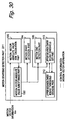
- Fig. 21 is a block diagram showing the structure of a video coding apparatus 121 in which a coding control apparatus 122 based on a coding control method according to each embodiment of the present invention described below is used.
- This video coding apparatus 121 comprises the coding control apparatus 122 and a video coding part 125.
- the video coding part 125 performs compression coding on a video signal Sv inputted in the video coding apparatus 121, thereby generating coded data Dc and outputs the coded data Dc from the video coding apparatus 121.
- the coding control apparatus 122 comprises a motion start/motion end detection part 123 and a quantization control part 124, and controls coding of the video signal Sv in the video coding part 125 by the coding control method according to each embodiment of the present invention.
- the motion start/motion end detection part 123 detects a motion start and a motion end of an object in a picture indicated by the input video signal Sv
- the quantization control part 124 employs the detection results and controls quantization in coding by the video coding part 125.
- each part of the aforementioned video coding apparatus 121 shown in FIG. 21 inclusive of the interior of the coding control apparatus 122 may be directly implemented by hardware, while the same can also be implemented employing software.
- each part of the video coding apparatus 121 can be implemented by forming the video coding apparatus with a CPU (Central Processing Unit), a memory and an external memory device so that the CPU executes a prescribed program (hereinafter referred to as "video coding program") loaded from the external memory device in the memory, for example.
- the video coding program is typically provided by a storage medium (flexible disk, CD-ROM, DVD or the like) storing the program.
- the user sets a purchased storage medium in the video coding apparatus 121, lets the video coding apparatus 121 read the video coding program stored therein and installs the same in a memory device such as a hard disk unit.
- a video coding program transmitted to the video coding apparatus 121 through a communication line online may be installed in the memory device.
- the maker may previously install the video coding program in the memory device before shipping the video coding apparatus 121.
- the program installed in such a manner is loaded in the memory from the memory device and executed by the CPU.
- a coding control program is also included in the aforementioned video coding program so that the CPU executes this coding control program, whereby coding of the video signal Sv is controlled.
- the CIF picture is of 352 by 288 dots, and in H. 261 or H.263, this is divided into 22 by 18 blocks in units of macroblocks of 16 by 16 dots, and a group of blocks (hereinafter referred to as "GOB") is further formed every 11 by 3 blocks.
- the CIF picture is formed by 2 by 6 GOBs, and each GOB is further formed by 11 by 3 macroblocks.
- a picture area of one frame is divided in coding control into not less than two areas.
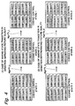
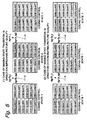
- This area is an area having an arbitrary magnitude and not restricted to an area of a GOB, while in each embodiment of the present invention this area is assumed to be a GOB for making description. It is assumed that "GOB" is used as an expression meaning a partial picture as the aforementioned set of pixels, and also used as an expression meaning an area of the partial picture. It is also assumed that among GOBs in each frame, GOBs having the same position in the frame are not distinguished but identified as the same GOBs, and referred to with assignment of the same number. Concretely, numbers from GOB1 to GOB12 are assigned to GOBs in the order shown in FIG. 1 and FIG. 2. Each GOB is coded with the quantization characteristic shown in FIG. 1 and FIG. 2. In other words, macroblocks forming each GOB are coded with the quantization characteristic shown in FIG. 1 and FIG. 2.
- an upper bound threshold and a lower bound threshold of a generated information amount are decided every state of the quantization characteristic, similarly to the conventional coding control method disclosed in JP-A-7-107482.
- These upper bound and lower bound thresholds are set to hold a target generated information amount set for the picture frame therebetween. It is assumed that these upper and lower thresholds are generally referred to as "state transition threshold”.
- coding control is so performed as to switch such coding that the quantization characteristic employed for coding each GOB forming one picture frame varies with the GOB and such coding that all are identical in response to a generated information amount resulting from coding one picture frame.
- a concept "coding control state" is introduced.
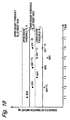
- FIG. 1 shows transition of the coding control state when the generated information amount falls below the lower bound of the state transition threshold and when the generated information amount exceeds the upper bound of the state transition threshold.
- coding control state 1 means such a state that all quantization characteristics employed for coding each GOB forming a picture frame are identical.
- coding control state 2 means a state previously dividing GOBs into two groups of first and second, assuming that all GOBs belonging to the same group are coded with the same quantization characteristic, and coding either group with the same quantization characteristic as a first coding control state 1 while coding the other group with the same quantization characteristic as a second coding control state 1 respectively.
- the first coding control state 1 corresponds to the certain state q(s) of the quantization characteristic in the aforementioned conventional coding control method
- the second coding control state 1 corresponds to the state q(s + 1) of the quantization characteristic subsequent to the state q(s).
- grouping in the coding control state 2 is so performed that the generated information amount of the first group and that of the second group are equal to each other when performing coding with the same quantization characteristic, whereby the object of the present invention is attained.
- This embodiment aims at, by spatially alternately arranging GOBs of different groups, substantially equally separating into two groups a background, a person and the like which are objects respectively. In this case, this aim is attained in higher precision, as an area forming the base is refined, while to what extent the refinement is performed becomes trade-off with the processing amount. It is hereinafter assumed that, among GOB1 to GOB12 forming one frame, GOB1, 4, 5, 8, 9 and 12 form the first group and GOB2, 3, 6, 7, 10 and 11 form the second group.
- FIG. 22 is a block diagram showing the structure of a quantization control part in the coding control apparatus according to this embodiment, i.e., a block diagram showing an exemplary structure of the quantization control part 124 in the aforementioned coding control apparatus 122 shown in FIG. 21 (it is hereinafter assumed that the quantization control part of this structure is denoted by reference numeral "131").
- This quantization control part 131 comprises a state transition threshold upper bound storage part 132, a state transition threshold lower bound storage part 133, a threshold comparison part 134 and a quantization characteristic decision part 135, inputs a signal indicating a generated information amount Aig resulting from coding one picture frame in the video coding part 125, decides quantization characteristics Q1 and Q2 employed for coding the GOBs of the first and second groups, and inputs signals indicating the decided quantization characteristics as control signals for quantization in the video coding part 125.
- the state transition threshold upper bound storage part 132 holds a predetermined upper bound Th_U of the state transition threshold
- the state transition threshold lower bound storage part 133 holds a predetermined lower bound Th_L of the state transition threshold respectively.
- the threshold comparison part 134 compares these upper bound Th_U and lower bound Th_L of the state transition threshold with the generated information amount Aig resulting from coding one picture frame, and if the generated information amount Aig is below the lower bound Th_L of the state transition threshold, it outputs a signal instructing change of the quantization characteristic in a direction improving the picture quality as a signal indicating a transition factor 1, while, if the generated information amount Aig is between the lower bound Th_L and the upper bound Th_U of the state transition threshold, it outputs a signal instructing maintenance of the picture quality as a signal indicating a transition factor 2, and, if the generated information amount Aig exceeds the upper bound Th_U of the state transition threshold, it outputs a signal instructing change of the quantization characteristic in a direction
- the quantization characteristic decision part 135 On the basis of the signal indicating any of these transition factors 1 to 3, the quantization characteristic decision part 135 outputs a signal indicating the quantization characteristic Q1 employed for coding the GOBs of the first group (hereinafter simply referred to as "quantization characteristic Q1 for the first group"), and a signal indicating the quantization characteristic Q2 employed for coding the GOBs of the second group (hereinafter simply referred to as "quantization characteristic Q2 for the second group"). These signals indicating the quantization characteristics Q1 and Q2 are inputted in the video coding part 125, and in the video coding part 125, coding of a next picture frame is performed with these quantization characteristics Q1 and Q2.
- FIG. 23 is a state transition diagram showing the operation of the quantization control part 131.
- the state of the quantization control part 131 corresponds to the combination of the quantization characteristic Q1 for the first group and the quantization characteristic Q2 for the second group.
- quantization state the state of the quantization control part
- the quantization characteristics are identified with natural numbers, and largeness/smallness of a quantization characteristic j corresponds to largeness/smallness of j. As j increases, therefore, the quantization step size also increases while quantization precision lowers.
- quantization characteristics are denoted as "QUANT".
- the aforementioned state transition is also transition from the coding control state 1 to the coding control state 2. Thereafter when the transition factor 1 takes place in the quantization state S 2 , the state of the quantization control part 131 returns to the quantization state S 1 belonging to the coding control state 1, and the quantization characteristic decision part 135 outputs, as the signal indicating the quantization characteristic Q1 for the first group and the quantization characteristic Q2 for the second group, signals both indicating the quantization characteristic 1.
- the quantization characteristic decision part 135 outputs signals both indicating the quantization characteristic 2 as the quantization characteristic Q1 for the first group and the quantization characteristic Q2 for the second group.
- the state of the quantization control part 131 returns to the quantization state S 2 belonging to the coding control state 2, and the quantization characteristic decision part 135 outputs a signal indicating the quantization characteristic 1 as the quantization characteristic Q1 for the first group and a signal indicating the quantization characteristic 2 as the quantization characteristic Q2 for the second group respectively.
- the state of the quantization control part 131 makes transition to a quantization state S 4 belonging to the coding control state 2, and the quantization characteristic decision part 135 outputs a signal indicating the quantization characteristic 2 as the quantization characteristic Q1 for the first group and a signal indicating the quantization characteristic 3 as the quantization characteristic Q2 for the second group respectively.
- the quantization state of the quantization control part 131 makes transition, every time the transition factor 3 takes place, in a direction where the numerical value indicating the quantization characteristic increases, i.e., in a direction where the quantization precision lowers, while the quantization state makes transition, every time the transition factor 1 takes place, in a direction where the numerical value indicating the quantization characteristic reduces, i.e., in a direction where the quantization precision improves.
- the quantization decision part 135 outputs as signals indicating the quantization characteristics for the first and second groups signals indicating quantization characteristics corresponding to each quantization state of the transition destination. If the transition factor 2 takes place in each quantization state, the quantization control part 131 remains in the quantization state, and output signals from the quantization characteristic decision part 135 remain unchanged.
- the generated information amount resulting from performing coding with the quantization characteristic q(s), i.e., the generated information amount denoted by the point d in FIG. 7A changes due to state transition to the quantization state of the quantization characteristic q(s+ 1) to the generated information amount denoted by the point e' in FIG. 7A
- a coding control state using the quantization characteristic q(s) for coding the GOBs of the first group and the quantization characteristic q(s + 1) for coding the second group respectively and a coding state using the quantization characteristic q(s + 1) for coding the GOBs of the first group and the quantization characteristic q(s) for coding the second group can be created as separate coding control states between the first coding control state 1 and the second coding control state 1.
- the quantization characteristics can be more finely set, whereby fluctuation of the generated information amount can be more reduced.
- the quantization characteristics employed in coding the next picture frame may be decided on the basis of an occupied amount in a smoothing buffer (transmission buffer) for transmitting coded data.
- FIG. 24 is a block diagram showing the structure of a quantization control part in a coding control apparatus according to this embodiment, i.e., a block diagram showing another exemplary structure of the quantization control part 124 in the aforementioned coding control apparatus 122 shown in FIG. 21 (it is hereinafter assumed that the quantization control part of this structure is denoted by reference numeral "151").
- this quantization control part 151 comprises a state transition threshold upper bound storage part 132, a state transition threshold lower bound storage part 133, a threshold comparison part 134 and a quantization characteristic decision part 153.
- the quantization control part 151 comprises a time axis placement control part 152, and differs in this point from the quantization control part 131 in the first embodiment.
- this time axis placement control part 152 inputs control signals, for exchanging a quantization characteristic Q1 for a first group and a quantization characteristic Q2 for a second group every picture frame, in the quantization characteristic decision part 153.
- the quantization control state 2 it outputs a signal indicating a transition factor 4 letting the quantization state make transition in the coding control state 2 so that the quantization characteristic Q1 for the first group is greater than the quantization characteristic Q2 for the second group and a signal indicating a transition factor 5 letting the quantization state make transition in the coding control state 2 so that the quantization characteristic Q1 for the first group is less than the quantization characteristic Q2 for the second group every picture frame alternately in the quantization characteristic decision part 153.
- largeness/smallness of the quantization characteristic corresponds to largeness/smallness of the quantization step size. Therefore, if the quantization characteristic for the first group is greater than the quantization characteristic for the second group, for example, the quantization precision in coding of GOBs of the first group is lower than the quantization precision in coding of GOBs of the second group.
- the quantization characteristic decision part 153 in this embodiment inputs, on the basis of a signal indicating any of transition factors 1 to 3 outputted from the threshold comparison part 134 and a signal indicating the transition factor 4 or 5 outputted from the time axis placement control part 152, a signal indicating the quantization characteristic Q1 for the first group and a signal indicating the quantization characteristic Q2 for the second group as control signals for quantization in the video coding part 125.
- the remaining elements in the quantization control part 151, other than the aforementioned time axis placement control part 152 and quantization characteristic decision part 153, are similar to those in the first embodiment, and the same reference numerals are assigned to the same parts.
- FIG. 25 is a state transition diagram showing the operation of the quantization control part 151.
- the quantization control part 151 has quantization states S 1 to S 61 similar to those in the first embodiment shown in FIG. 23.
- the quantization control part 151 further has, in addition to these quantization states S 1 to S 61 , quantization states S 2r , S 4r , ..., S 60r corresponding to the quantization states S 2 , S 4 , ..., S 60 belonging to the respective ones of the coding control state 2.
- the quantization control part 151 is in a certain quantization state S 2i belonging to the coding control state 2 (i.e., the case of Q1 ⁇ Q2 ).
- the quantization control part 151 makes transition to the quantization state S 2ir , and the quantization characteristic decision part 153 outputs signals exchanging the signal indicating the quantization characteristic Q1 for the first group and the signal indicating the quantization characteristic Q2 for the second group in the quantization state S 2i before the transition as the control signals for quantization.
- the quantization characteristic decision part 153 outputs a signal indicating a quantization characteristic (i + 1) as the quantization characteristic Q1 for the first group and a signal indicating a quantization characteristic i as the quantization characteristic Q2 for the second group respectively. Thereafter, when both the transition factor 2 and the transition factor 5 take place in this quantization state S 2ir , the state of the quantization control part 151 returns to the quantization state S 2i , and the quantization characteristic decision part 153 outputs a signal indicating the quantization characteristic i as the quantization characteristic Q1 for the first group and a signal indicating the quantization characteristic (i + 1) as the signal indicating the quantization characteristic Q2 for the second group respectively.
- a signal indicating the transition factor 2 is a signal instructing maintenance of the picture quality, and indicates that a generated information amount Aig is between an upper bound and a lower bound of a state transition threshold.
- the transition factor 4 indicates a factor letting the quantization state make transition in the coding control state 2 so that Q1 > Q2
- the transition factor 5 indicates a factor letting the quantization state make transition in the coding control state 2 so that Q1 ⁇ Q2
- the signal indicating the transition factor 4 and the signal indicating the transition factor 5 are every picture frame alternately inputted in the quantization characteristic decision part 153.
- state transition is repeated between the quantization states S 2i and S 2ir , whereby every picture frame a quantization characteristic for GOBs having improved the picture quality and a quantization characteristic for GOBs having not improved the picture quality are exchanged. Consequently, the GOBs having improved the picture quality disperse in relation to the time direction.
- the state of the quantization control part 151 returns to a quantization state S 2i-1 belonging to the coding control state 1, and the quantization characteristic decision part 153 outputs signals both indicating the quantization characteristic i as the quantization characteristic Q1 for the first group and the quantization characteristic Q2 for the second group.
- the state of the quantization control part 151 makes transition to a quantization state S 2i+1 belonging to the coding control state 1, and the quantization characteristic decision part 153 outputs signals both indicating the quantization characteristic (i + 1) as the quantization characteristic Q1 for the first group and the quantization characteristic Q2 for the second group.
- the quantization characteristic q(s) employed for coding each GOB is entirely the quantization characteristic 5, i.e., the state of the quantization control part 151 is the quantization state S 9 (first coding control state 1), and the operation in the case where the quantization state makes transition in a direction improving the picture quality is described with reference to FIG. 1.
- the state of the quantization control part 151 makes transition to the quantization state S 8 belonging to the coding control state 2, while the quantization characteristic employed for coding GOBs of the first group, i.e., GOB1, 4, 5, 8, 9 and 12 is changed by the quantization characteristic decision part 153 from 5 to 4 so that the GOBs improving the picture quality disperse.
- the state of the quantization control part 151 is held in the coding control state 2 while the quantization characteristic for the GOBs having improved the picture quality and the quantization characteristic for the GOBs having not improved the picture quality are exchanged by the quantization characteristic decision part 153 so that the GOBs having improved the picture quality disperse also in relation to the time direction.
- the quantization state alternately makes transition in the coding control state 2 between a quantization state S 8 and a quantization state S 8r .
- This is performed for the purpose of rendering non-uniformity of the picture quality resulting from the quantization characteristic varying with each GOB inconspicuous.
- the quantization characteristics are so set in the quantization state S 8r as to code GOB2, 3, 6, 7, 10 and 11 which are the GOBs of the second group with the quantization characteristic 4 and to code the GOBs of the first group which are the remaining GOBs with the quantization characteristic 5.
- the state of the quantization control part 151 makes transition to a quantization state S 7 belonging to the coding control state 1 (second coding control state 1), and the quantization characteristic is so set by the quantization characteristic decision part 153 as to code each GOB entirely with the quantization characteristic 4.
- the coding control state makes transition in a direction deteriorating the picture quality, i.e., when the generated information amount Aig exceeds the upper bound Th_U of the state transition threshold, it operates in a procedure reverse to the aforementioned case where the coding control state makes transition in the direction improving the picture quality, and hence description is omitted.
- the second coding control state 1 is replaced by the first coding control state 1 in the above description and the subsequent operation is performed.
- the generated information amount Aig exceeds the upper bound Th_U of the state transition threshold in the first coding control state 1
- the first coding control state 1 is replaced by the second coding control state 1 in the above description and the subsequent operation is performed.
- the average state of the states q(s) and q(s + 1) of the quantization characteristic is introduced, thereby reducing errors between the generated information amount resulting from coding and the target generated information amount and improving control precision of the generated information amount Aig by the quantization control part 151.
- the quantization characteristic Q1 for the GOBs of the first group and the quantization characteristic Q2 for the second group are exchanged every picture frame.
- the quantization characteristic for the GOBs having improved the picture quality and the quantization characteristic for the GOBs having not improved the picture quality are exchanged every frame.
- FIG. 26 is a block diagram showing the structure of a quantization control part in a coding control apparatus according to this embodiment, i.e., a block diagram showing a third exemplary structure of the quantization control part 124 in the aforementioned coding control apparatus 122 shown in FIG. 21 (it is hereinafter assumed that the quantization control part of this structure is denoted by reference numeral "171").
- This quantization control part 171 comprises, similarly to the quantization control part 151 in the second embodiment shown in FIG. 24, a state transition threshold upper bound storage part 132, a state transition threshold lower bound storage part 133, a threshold comparison part 134, a time axis placement control part 152 and a quantization characteristic decision part 175.
- the quantization control part 171 comprises a state transition step width control part 172, a first state transition step width control threshold storage part 173 and a second state transition step width control threshold storage part 174, and differs in this point from the quantization control part 151 in the second embodiment.
- the first state transition step width control threshold storage part 173 holds a first state transition step width control threshold Th_stp1 as a predetermined value
- the second state transition step width control threshold storage part 174 holds a second state transition step width control threshold Th_stp2 as a predetermined value respectively.
- the state transition step width control part 172 compares these state transition step width control thresholds Th_stp1 and Th_stp2 with a generated information amount Aig resulting from coding one picture frame, and if the generated information amount Aig exceeds the first state transition step width control threshold Th_stp1 or the generated information amount Aig falls below the second state transition step width control threshold Th_stp2, it outputs a signal instructing skipping of one quantization state as a signal indicating a transition factor 6, while, if the generated information amount Aig is between the first state transition step width control threshold Th_stp1 and the second state transition step width control threshold Th_stp2, it outputs a signal instructing an operation of not skipping but making transition one quantization state at a time as a signal indicating a transition factor 7.
- the quantization characteristic decision part 175 generates, on the basis of a signal indicating any of transition factors 1 to 3 outputted from the threshold comparison part 134, a signal indicating a transition factor 4 or 5 outputted from the time axis placement control part 152 and a signal indicating a transition factor 6 or 7 outputted from the state transition step width control part 172, a signal indicating a quantization characteristic Q1 for a first group and a signal indicating a quantization characteristic Q2 for a second group as control signals for quantization, to input these signals into a video coding part 125.
- the remaining elements other than the aforementioned state transition step width control part 172, first state transition step width control threshold storage part 173, second state transition step width control threshold storage part 174 and quantization characteristic decision part 175 in the quantization control part 171 are similar to those in the second embodiment, and the same reference numerals are assigned to the same parts.
- FIG. 27 is a state transition diagram showing the operation of the quantization control part 171.
- the quantization control part 171 has quantization states S 1 , S 2 , ..., S 61 and quantization states S 2r , S 4r , ..., S 60r similar to those in the second embodiment shown in FIG. 25.
- state transition skipping one quantization state is present in addition to the state transition in the second embodiment, and in this point the state transition of this embodiment differs from the state transition of the second embodiment. This difference is now described.
- While the generated information amount Aig is between the first state transition step width control threshold Th_stp1 and the second state transition step width control threshold Th_stp2, a signal indicating the transition factor 7 is outputted from the state transition step width control part 172, and state transition similar to that in the second embodiment is performed in response to the signal outputted from the threshold comparison part 134.
- a signal indicating the transition factor 6 is outputted from the state transition step width control part 172, and in response to the signal indicating the transition factor 1 or 3 outputted from the threshold comparison part 134, state transition skipping one quantization state is performed.
- the state of the quantization control part 171 skips a quantization state S i-1 and makes transition to a quantization state S i-2 if the signal indicating the transition factor 6 and the signal indicating the transition factor 1 are outputted, while skipping a quantization state S i+1 and making transition to a quantization state S i+2 if the signal indicating the transition factor 6 and the signal indicating the transition factor 3 are outputted.
- the state of the quantization control part 171 skips a quantization state S j-1 and makes transition to a quantization state S (j-2)r if the signal indicating the transition factor 6 and the signal indicating the transition factor 1 are outputted, while skipping a quantization state S j+1 and making transition to a quantization state S (j+2)r if the signal indicating the transition factor 6 and the signal indicating the transition factor 3 are outputted.
- inter-frame correlation abruptly lowers if abrupt motion of an object or scene change takes place, and hence a generated information amount abruptly increases.
- the generated information amount abruptly reduces.
- a state of coding GOBs in one picture frame with a plurality of quantization characteristics exists and hence, if the generated information amount abruptly increases or the generated information amount abruptly reduces, a delay occurs before setting a quantization characteristic approximating the generated information amount to a target generated information amount (or between the upper bound and the lower bound of the state transition threshold).
- a phenomenon takes place that frame skip is caused when the generated information amount abruptly increases or coding is performed with a quantization characteristic for inferior picture quality although coding can be performed with a quantization characteristic capable of further improving the picture quality when the generated information amount abruptly reduces.
- the first state transition step width control threshold Th_stp1 and the second state transition step width control threshold Th_stp2 are previously set, and when the generated information amount Aig exceeds the first state transition step width control threshold Th_stp1 or the generated information amount Aig falls below the second state transition step width control threshold Th_stp2, coding control increasing the state transition step width and quickly approximating the generated information amount to the target generated information amount is performed.
- FIG. 2 indicates transition of the quantization state when the generated information amount Aig exceeds the first state transition step width control threshold Th_stp1 and when the generated information amount Aig falls below the second state transition step width control threshold Th_stp2.
- a coding control state 1 means, similarly to the exemplary operation of the first embodiment shown in FIG. 1, such a state that all quantization characteristics for coding each GOB forming a picture frame are identical.
- all quantization characteristics employed for coding each GOB are the quantization characteristic 5, i.e., the state of the quantization control part 171 is a quantization state S 9 belonging to the coding control state 1, to consider the case where the quantization state makes transition in the direction improving the picture quality. If the generated information amount Aig when coding each GOB with the quantization characteristic 5 falls below the lower bound Th_L of the state transition threshold and further falls below the second state transition step width control value Th_stp2, all quantization characteristics for each GOB are changed by the quantization control part 171 in the direction improving the picture quality, i.e., changed from the quantization characteristic 5 to the quantization characteristic 4.
- the state of the quantization control part 171 skips a quantization state S 8 belonging to the coding control state 2 and makes transition to a quantization state S 7 belonging to the coding control state 1. If the generated information amount Aig when coding each GOB with the quantization characteristic 4 again falls below the lower bound Th_L of the state transition threshold and further falls below the second state transition step width control threshold Th_stp2, all quantization characteristics for each GOB are changed by the quantization control part 171 in the direction improving the picture quality, i.e., changed from the quantization characteristic 4 to the quantization characteristic 3. This means that the state of the quantization control part 171 skips a quantization state S 6 belonging to the coding control state 2 and makes transition to a quantization state S 5 belonging to the coding control state 1.
- the quantization state makes transition in the direction deteriorating the picture quality, i.e., when the generated information amount Aig exceeds the upper bound Th_U of the state transition threshold and further exceeds the first state transition step width control threshold Th_stp1, it operates in a procedure reverse to the aforementioned case where the quantization state makes transition in the direction improving the picture quality, and hence description is omitted.
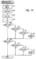
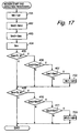
- FIG. 3 is a flow chart showing coding control processing for one picture frame according to this coding control method.
- quantization characteristics are denoted as "QUANT”.
- q1 and q2 are numerical values identifying the quantization characteristics
- Scc is a variable denoting the coding control state
- Ft is a time axis control flag, and it is assumed that q1, q2, Scc and Ft are previously initialized.
- the threshold comparison part 134 first determines whether or not the generated information amount Aig resulting coding one picture frame exceeds the upper bound Th_U of the state transition threshold (step 301). If as the result the generated information amount Aig exceeds the upper bound Th_U of the state transition threshold, steps 302 to 309 are carried out to let the quantization state make transition in the direction reducing quantization precision, i.e., the direction deteriorating the picture quality, in order to approximate the generated information amount in one picture frame to a target generated information amount.
- the state transition step width control part 172 first determines whether or not the generated information amount Aig exceeds the first state transition step width control threshold Th_stp1 (step 302). If, as the result, the generated information amount Aig exceeds the first state transition step width control threshold Th_stp1, inter-frame correlation abruptly lowers and the generated information amount is determined as abruptly increasing, and hence, in order to reduce the quantization precision in coding of each GOB in both of the first and second groups, the quantization characteristic decision part 175 increments q1 and q2 (steps 304 and 305). Thus, the quantization state makes transition in the direction reducing the quantization precision in a state transition width larger than the general one. Thereafter the process advances to a step 319.
- the quantization characteristic decision part 175 determines whether or not the variable Scc denoting the coding control state is "1" (step 303). If, as the result, the variable Scc is "1", the quantization characteristic decision part 175 increments q2 (step 306) and sets the variable Scc to "2" (step 307), in order to lower the quantization precision of the GOBs of either group among the GOBs of the first and second groups.
- the quantization characteristic decision part 175 increments q1 (step 308) and sets the variable Scc to "1" (step 309), in order to lower the quantization precision of each GOB of the remaining group among the GOBs of the first and second groups. Thereafter the process advances to the step 319.
- the threshold comparison part 134 determines whether or not the generated information amount Aig of one frame is below the lower bound Th_L of the state transition threshold (step 310). If, as the result, the generated information amount Aig is below the lower bound Th_L of the state transition threshold, steps 311 to 318 are carried out to let the quantization state make transition in the direction increasing the quantization precision, i.e., in the direction improving the picture quality, in order to approximate the generated information amount of one picture frame to the target generated information amount.
- the state transition step width control part 172 first determines whether or not the generated information amount Aig exceeds the second state transition step width control threshold Th_stp2 (step 311). If, as the result, the generated information amount Aig is below the second state transition step width control threshold Th_stp2, the inter-frame correlation abruptly rises and the generated information amount is determined as abruptly reducing, and hence the quantization characteristic decision part 175 decrements q1 and q2 (steps 313 and 314), in order to increase the quantization precision in coding of each GOB of both of the first and second groups. Thus, the quantization state makes transition in the direction increasing the quantization precision in a state transition width larger than the general one. Thereafter the process advances to the step 319.
- the quantization characteristic decision part 175 determines whether or not the variable Scc denoting the coding control state is "1" (Step 312). If, as the result, the variable Scc is 1, the quantization characteristic decision part 175 decrements q1 (step 315) and sets the variable Scc to "2" (step 316), in order to increase the quantization precision of each GOB of either group among the GOBs of the first and second groups.
- the quantization characteristic decision part 175 decrements q2 (step 317) and sets the variable Scc to "1" (step 318), in order to increase the quantization precision of each GOB of the remaining group among the GOBs of the first and second groups. Thereafter the process advances to the step 319.
- the process advances to the step 319.
- the quantization characteristic decision part 175 determines whether or not the time axis placement control flag Ft is "1".
- This time axis control flag Ft is a flag used for exchanging GOBs having superior picture quality and GOBs having inferior picture quality in the picture frame every frame.
- GOB1, 4, 5, 8, 9 and 12 i.e., each GOB of the first group is coded with the quantization characteristic q1 and the remaining GOBs, i.e., each GOB of the second group is coded with the quantization characteristic q2.
- each GOB of the second group is coded with the quantization characteristic q1
- the remaining GOBs i.e., each GOB of the first group is coded with the quantization characteristic q2.
- the quantization characteristic decision part 175 sets, on the basis of the result of the determination at the step 319, the quantization characteristic for each GOB of the first group at the quantization characteristic q1 and the quantization characteristic for each GOB of the second group at the quantization characteristic q2 respectively (step 320) if the time axis placement control flag Ft is "1", while setting the quantization characteristic for each GOB of the first group at the quantization characteristic q2 and the quantization characteristic for each GOB of the second group at the quantization characteristic q1 (step 321) if the time axis placement control flag Ft is not "1".
- These steps 320 and 321 decide spatial arrangement of the GOBs having superior picture quality and the GOBs having inferior picture quality in the picture frame. Due to this spatial arrangement, the GOBs having superior picture quality are prevented from biasing in the picture frame or the GOBs having inferior picture quality are prevented from biasing in the picture frame.
- the time axis placement control part 152 sets this time axis placement control flag Ft to "2". In the case where the time axis placement control flag Ft is "2", after execution of the step 321, the time axis placement control part 152 sets this time axis placement control flag Ft to"1". Due to these steps 322 and 323, "1" and “2" are alternately set for the time axis placement control flag every frame, and consequently the steps 320 and 321 are alternately carried out every frame.
- one picture frame is coded with the two types of quantization characteristics q1 and q2 ( q1 ⁇ q2 ) and the GOBs having superior picture quality and the GOBs having inferior picture quality are present, while the steps 320 and 321 are thus alternately carried out every frame and hence the GOBs having improved the picture quality disperse also in the time direction.
- the quantization characteristics for one picture frame to be currently coded are set in the aforementioned manner, coding control for one picture frame terminates.
- the quantization characteristics thus set steps 320 and 321
- coding for one picture frame is performed by the video coding part 125.
- coding control for the next one picture frame is performed similarly to the above.
- the quantization characteristics for the picture frame to be currently coded can be finely set on the basis of the generated information amount Aig of the previously coded picture frame with a simple algorithm by introduction of the coding control states 1 and 2, whereby dispersion of the picture quality or fluctuation of the generated information amount in one picture frame is small and a visually excellent motion picture having no frame skip can be obtained.
- the quantization characteristic for the GOBs having improved the picture quality and the quantization characteristic for the GOBs having not improved the picture quality are exchanged every frame in the coding control state 2, whereby the GOBs having improved the picture quality are not only spatially dispersed but also dispersed in relation to the time direction, and non-uniformity of the picture quality resulting from the quantization characteristics varying with the GOBs is inconspicuous.
- the third embodiment further, even if the inter-frame correlation abruptly rises or lowers and hence abrupt increase/decrease of the generated information amount takes place, coding can be quickly performed with quantization characteristics responsive to the characteristics of the picture by increasing the state transition step width with state transition skipping one quantization state.
- the quantization characteristics are decided in units of the GOBs so that quantization employed for coding may not be transmitted every macroblock to the decoding side, whereby the transmission band can be effectively utilized and a motion picture having excellent picture quality can be obtained.
- the quantization characteristics can be more finely set and hence fluctuation of the generated information amount can be further reduced.
- coding control responsive to the throughput can be performed by adding processing of calculating average throughput Tp_av from an information amount transmitted within a predetermined constant time and correcting the upper bound Th_U and the lower bound Th_L of the state transition threshold as well as the first state transition step width control threshold Th_stp1 and the second state transition step width control threshold Th_stp2 through the following equations.
- Th_Ua Th_U ⁇ Tp_av
- Th_La Th_L ⁇ Tp_av
- Th_stp1a Th_stp1 ⁇ Tp_av
- Th_stp2a Th_stp2 ⁇ Tp_av (0 ⁇ Tp_av ⁇ 1)
- This embodiment applies the present invention to a video transmission system transmitting a CIF picture of H.261 or H.263 recommended by ITU, which is a video transmission system having a function of performing refresh by INTRA coding when mismatch between frame memories of a transmission side and a receiving side takes place due to a transmission error.
- the aforementioned refresh function INTRA-codes one GOB every picture frame and thereby performing forced updating.
- FIG. 4 and FIG. 5 show an example of INTRA-coding GOB1 in the first picture frame, INTRA-coding GOB2 in the next picture frame, and INTRA-coding GOB3 in the subsequent picture frame.
- the structure of the coding control apparatus according to this embodiment is similar to the coding control apparatus 122 of the third embodiment comprising the quantization control part 171 shown in FIG. 26 except the point that the same has no time axis placement control part 152, and hence it is assumed that the same numerals are assigned to the same parts and description of each part is omitted.
- FIG. 4 shows transition of a quantization state when a generated information amount Aig resulting from coding one picture frame falls below a lower bound Th_L of a state transition threshold and when the generated information amount Aig exceeds an upper bound Th_U of the state transition threshold.
- a coding control state 1 means such a state that all quantization characteristics employed for coding each GOB forming the picture frame are identical
- a coding control state 2 means such a state that GOBs are previously divided into two groups (in this embodiment, divided into a group formed by one GOB to be INTRA-coded and a group formed by a plurality of GOBs to be INTER-coded) and the quantization characteristic employed for coding the GOB(s) in the same group is identical and quantization characteristics employed for coding the GOBs of the different groups are different.
- the quantization characteristic for each GOB is entirely set by a quantization characteristic decision part 175 at a quantization characteristic 4 and the state of the coding control apparatus again makes transition to the coding control state 1, i.e., the state of the quantization control part makes transition to a quantization state corresponding to a second coding control state 1.
- the state of the quantization control part makes transition to a quantization state belonging to the coding control state 2, while the quantization characteristic for the GOBs (GOB1 and GOB3 to 12) other than the GOB subjected to INTRA coding is changed by the quantization characteristic decision part 175 in the direction deteriorating the picture quality from 3 to 4.
- inter-frame correlation In video coding based on ITU recommendation H.261 or H.263 attaining high compressibility by employing inter-frame difference, inter-frame correlation abruptly lowers if abrupt motion of the object or scene change takes place, and hence a generated information amount abruptly increases. When the inter-frame correlation abruptly rises, on the other hand, the generated information amount abruptly reduces. In the coding control described with reference to FIG.
- a state such as the coding control state 2 which codes GOBs in one picture frame with a plurality of quantization characteristics i.e., the coding control state 2
- the coding control state 2 which codes GOBs in one picture frame with a plurality of quantization characteristics
- a delay occurs before setting a quantization characteristic approximating the generated information amount to a target generated information amount (between the upper bound and the lower bound of the state transition threshold), and such a phenomenon takes place that frame skip is caused in the case where the generated information amount abruptly increases or coding is performed with a quantization characteristic for inferior picture quality although coding can be performed with a quantization characteristic capable of further increasing the picture quality in the case where the generated information amount abruptly reduces.
- a first state transition step width control threshold Th_stp1 and a second state transition step width control threshold Th_stp2 are previously set, and when the generated information amount Aig exceeds the first state transition step width control threshold Th_stp1 or the generated information amount Aig falls below the second state transition step width control threshold Th_stp2, coding control increasing the state transition step width and quickly approximating the generated information amount to the target generated information amount is performed.
- FIG. 5 shows transition of the quantization state when the generated information amount Aig exceeds the first state transition step width control threshold Th_stp1 and when the generated information amount Aig falls below the second state transition step width control threshold.
- the coding control state 1 means, similarly to the exemplary operation shown in FIG. 4, such a state that all quantization characteristics for coding each GOB forming the picture frame are identical.
- the quantization state has made transition from the first coding control state 1 to the second coding control state 1 skipping the coding control state 2. If the generated information amount Aig when coding each GOB with the quantization characteristic 4 again falls below the lower bound Th_L of the state transition threshold and further falls below the second state transition step width control threshold Th_stp2, the quantization characteristic for each GOB is entirely changed by the quantization control part 171 in the direction improving the picture quality from 4 to 3. This means that the quantization state has made transition from the second coding control state 1 to a third coding control state 1 skipping the coding control state 2.
- the quantization state makes transition in the direction deteriorating the picture quality, i.e., when the generated information amount Aig exceeds the upper bound Th_U of the state transition threshold and further exceeds the first state transition step width control threshold Th_stp1, it operates in a procedure reverse to the aforementioned case where the quantization state makes transition in the direction improving the picture quality, and hence description is omitted.
- FIG. 6 is a flow chart showing coding control processing for one picture frame by this coding control method.
- quantization characteristics are denoted as "QUANT”.
- q1 and q2 are numerical values identifying the quantization characteristics
- Scc is a variable denoting the coding control state
- Ft is a time axis control flag, and it is assumed that q1, q2, Scc and Ft are previously initialized.
- a threshold comparison part 134 first determines whether or not the generated information amount Aig resulting from coding one picture frame exceeds the upper bound Th_U of the state transition threshold (step 601). If as the result the generated information amount Aig exceeds the upper bound Th_U of the state transition threshold, steps 602 to 609 are carried out and thereby letting the quantization state make transition in a direction reducing quantization precision, i.e., in the direction deteriorating the picture quality, in order to approximate the generated information amount of one picture frame to a target generated information amount.
- a state transition step width control part 172 first determines whether or not the generated information amount Aig exceeds the first state transition step width control threshold Th_stp1 (step 602). If, as the result, the generated information amount Aig exceeds the first state transition step width control threshold Th_stp1, inter-frame correlation abruptly lowers and the generated information amount is determined as abruptly increasing, and hence the quantization characteristic decision part 175 increments q1 and q2 (steps 604 and 605), in order to reduce quantization precision of both of the GOB to be INTRA-coded and the GOBs to be INTER-coded.
- the quantization state makes transition in the direction reducing the quantization precision in a state transition width larger than the general one.
- the quantization characteristic decision part 175 determines whether or not the variable Scc denoting the coding control state is "1" (step 603). If, as the result, the variable Scc is 1, the quantization characteristic decision part 175 increments q2 (step 606) and sets the variable Scc to "2" (step 607), in order to lower the quantization precision of each GOB to be INTER-coded.
- the quantization characteristic decision part 175 increments q1 (step 608) and sets the variable Scc to "1" (step 609), in order to lower the quantization precision of the GOB to be INTRA-coded. Thereafter the process advances to the step 619.
- the threshold comparison part 134 determines whether or not the generated information amount Aig of one picture frame is below the lower bound Th_L of the state transition threshold (step 610). If, as the result, the generated information amount Aig is below the lower bound Th_L of the state transition threshold, steps 611 to 618 are carried out and thereby letting the quantization state make transition in the direction increasing the quantization precision, i.e., in the direction improving the picture quality, in order to approximate the generated information amount of one picture frame to the target generated information amount.
- the state transition step width control part 172 first determines whether or not the generated information amount Aig exceeds the second state transition step width control threshold Th_stp2 (step 611). If, as the result, the generated information amount Aig is below the second state transition step width control threshold Th_stp2, inter-frame correlation abruptly rises and the generated information amount is determined as abruptly reducing, and hence the quantization characteristic decision part 175 decrements q1 and q2 (steps 613 and 614), in order to increase the quantization precision of both of the GOB to be INTRA-coded and the GOBs to be INTER-coded.
- the quantization state makes transition in the direction increasing the quantization precision in a state transition width larger than the general one.
- the quantization characteristic decision part 175 determines whether or not the variable Scc denoting the coding control state is "1" (step 612). If, as the result, the variable Scc is 1, the quantization characteristic decision part 175 decrements q1 (step 615) and sets the variable Scc to "2" (step 616), in order to increase the quantization precision of the GOB to be INTRA-coded.
- the quantization characteristic decision part 175 decrements q2 (step 617) and sets the variable Scc to "1" (step 618), in order to increase the quantization precision of each GOB to be INTER-coded. Thereafter the process advances to the step 619.
- the process advances to the step 619.
- the quantization characteristic decision part 175 sets the quantization characteristic for the GOB to be INTRA-coded at the quantization characteristic q1.
- the quantization characteristic decision part 175 sets the quantization characteristic for the GOBs not INTRA-coded, i.e., the GOBs to be INTER-coded at q2.
- the quantization characteristics for the picture frame can be finely set with a simple algorithm, whereby dispersion of the picture quality or fluctuation of a generated information amount in one picture frame is small and a visually excellent motion picture having no frame skip can be obtained.
- the fourth embodiment similarly to the third embodiment, even if inter-frame correlation abruptly rises or lowers and hence abrupt increase/decrease of the generated information amount takes place, coding can be quickly performed with quantization characteristics responsive to the characteristics of the picture by increasing the state transition step width.
- the quantization characteristics are decided in units of the GOBs so that quantization employed for coding may not be transmitted every macroblock to the decoding side, whereby the transmission band can be effectively utilized and a motion picture having excellent picture quality can be obtained.
- a generated information amount of a plurality of previously coded picture frames may be held for performing state transition with a generated information amount per frame which is the average value thereof.
- coding control not influenced by temporary increase/decrease of the generated information amount can be performed.
- the quantization characteristics can be more finely set and hence fluctuation of the generated information amount can be further reduced.
- the present invention can be also applied to coding of a picture in which forced updating is intermittently inserted.
- coding control responsive to the throughput can be performed by adding processing of calculating average throughput Tp_av from an information amount transmitted within a predetermined constant time and correcting the upper bound Th_U and the lower bound Th_L of the state transmission threshold as well as the first state transition step width control threshold Th_stp1 and the second state transition step width control threshold Th_stp2 through the following equations.
- Th_Ua Th_U ⁇ Tp_av
- Th_La Th_L ⁇ Tp_av
- Th_stp1a Th_stp1 ⁇ Tp_av
- Th_stp2a Th_stp2 ⁇ Tp_av (0 ⁇ Tp_av ⁇ 1)
- the structure of the coding control apparatus according to this embodiment is similar to the coding control apparatus 122 of the third embodiment comprising the quantization control part 171 shown in FIG. 26 except the point that it has no time axis placement control part 152, and hence it is assumed that the same numerals are assigned to the same parts and description of each part is omitted.
- FIG. 9 shows transition of the quantization state when a generated information amount Aig resulting from coding one picture frame falls below a lower bound Th_L of a state transition threshold and when the generated information amount Aig exceeds an upper bound Th_U of the state transition threshold.
- a coding control state 1 means such a state that all quantization characteristics employed for coding each GOB forming the picture frame are identical
- a coding control state 2 means such a state that GOBs are previously divided into two groups (in this embodiment, divided into a group formed by one GOB to be INTRA-coded and a group formed by a plurality of GOBs to be INTER-coded) and the quantization characteristic employed for coding the GOB(s) in the same group is identical and quantization characteristics employed for coding the GOBs of the different groups are different.
- the state of the quantization control part makes transition to a quantization state belonging to the coding control state 2, while the quantization characteristic for the GOBs (GOB1 and GOB3 to 12) other than the GOB subjected to INTRA coding is changed by the quantization characteristic decision part 175 in the direction deteriorating the picture quality from 3 to 4.
- FIG. 10 is a flow chart showing coding control processing for one picture frame by the coding control method according to this embodiment.
- Steps 1101 to 1118 in the flow chart of FIG. 10 correspond to the steps 601 to 608 in the flow chart of FIG. 6 showing the coding control method according to the fourth embodiment respectively.
- processing similar to the step corresponding to each step among the steps 601 to 608 is performed, and hence description thereof is omitted.
- processing formed by steps 1119 to 1123 in the flow chart of FIG. 10 corresponds to the processing formed by the steps 619 and 620 in the flow chart of FIG. 6, while the processing is different.
- the quantization characteristic decision part 175 first compares at the step 1119 two numerical values q1 and q2 indicating quantization characteristics and determines whether or not q1 is greater than q2. If q1 > q2, as the result, the quantization characteristic decision part 175 sets the quantization characteristic for the GOB to be INTRA-coded at the quantization characteristic q2, and sets the quantization characteristic for the GOBs to be INTER-coded at q1.
- the quantization characteristic decision part 175 sets the quantization characteristic for the GOB to be INTRA-coded at the quantization characteristic q1, and sets the quantization characteristic for the GOBs to be INTER-coded at q2.
- the quantization characteristic for each GOB is set so that the quantization precision of the GOB to be INTRA-coded is not lower than the quantization precision of the GOBs to be INTER-coded.
- the quantization precision of the GOB to be INTRA-coded is regularly higher than the quantization precision of the GOBs to be INTER-coded, whereby block distortion due to INTRA coding is reduced.
- the coding control apparatus 122 in the video coding apparatus 121 shown in FIG. 21 comprises the motion start/end detection part 123, and the motion start/end detection part 123 detects the motion start and the motion end of the object in the picture indicated by the input video signal Sv, while the quantization control part 124 employs the detection results and controls the quantization characteristics in coding by the video coding part 125.
- An embodiment of such a coding control apparatus 122 is now described as a sixth embodiment.
- FIG. 28 is a block diagram showing the structure of a motion start/end detection part in the coding control apparatus according to this embodiment, i.e., a block diagram showing an exemplary structure of the motion start/end detection part 123 in the coding control apparatus 122 shown in FIG. 21 (hereinafter it is assumed that a motion start/end detection part of this structure is denoted by reference numeral "191").
- This motion start/end detection part 191 comprises a motion vector absolute value sum calculation part 193, a motion vector absolute value sum storage part 192, a motion start detection part 194 and a motion end detection part 195, and inputs from a video coding part 125 a signal indicating motion vector information Imv of one picture frame.
- the motion vector absolute value sum calculation part 193 inputs into itself the motion vector information Imv of one picture frame from the video coding part 125, and calculates a motion vector absolute value sum Smv.
- the motion vector absolute value sum storage part 192 holds the calculated motion vector absolute value sum Smv.
- the motion start detection part 194 generates a signal indicating motion start information Ims with the motion vector absolute value sum Smv
- the motion end detection part 195 generates a signal indicating motion end information Ime with this motion vector absolute value sum Smv.
- FIG. 11 is an explanatory diagram for defining a motion start state and a motion end state of the object.
- the vertical axis in FIG. 11 shows the sum Smv of the absolute values of motion vectors of one picture frame, and the upper direction of this vertical axis is assumed to be a direction increasing the sum Smv of the absolute values of the motion vectors.
- the horizontal axis in FIG. 11 shows passage of time. Referring to FIG.
- threshold Th_M is a threshold employed for determination as to whether or not there is motion of the object, and it is determined that there is no motion of the object if the sum Smv of the absolute values of the motion vectors is less than the threshold Th_M, while it is determined that there is motion if it is greater than the threshold Th_M.
- motion end state means such a state that, as shown in FIG. 11, the sum Smv of the absolute values of the motion vectors exceeds the threshold value Th_M and the sum Smv of the absolute values of the motion vectors gradually reduces.
- motion start state means such a state that the sum Smv of the absolute values of the motion vectors exceeds the threshold value Th_M and the sum Smv of the absolute values of the motion vectors gradually increases.
- the vertical axis in FIG. 12 indicates a generated information amount, and the upper direction of this vertical axis is assumed to be a direction increasing the generated information amount.
- the horizontal axis in FIG. 12 shows passage of time.
- "Upper bound threshold Th_U” and “lower bound threshold Th_L” are similar to those described with reference to the prior art (those identical to the respective ones of the upper bound Th_U and the lower bound Th_L of the state transition threshold in each of the already described embodiments), and employed for setting the quantization characteristics. Referring to FIG.
- black circles “ ⁇ ” indicate a generated information amount resulting from coding one picture frame in the case of using the coding control apparatus according to this embodiment, while a white circle “ ⁇ ” indicates a generated information amount resulting from coding one picture frame in the case of using the conventional coding control apparatus.
- Those shown by the vertical axis and the horizontal axis of the graph and the meanings of "upper bound threshold Th_U” and “lower bound threshold Th_L” are also similar in FIGS. 13, 15, 16, 18 and 19 described later.
- a generated information amount Aig when coding one picture frame with a quantization characteristic q(s), has been between the upper bound threshold Th_U and the lower bound threshold Th_L.
- the generated information amount Aig is located between the upper bound threshold Th_U and the lower bound threshold Th_L, and hence a next frame is coded while the quantization characteristic is left intact.
- a background having a fine pattern hidden behind the object appears due to movement of the object and the generated information amount Aig resulting from performing coding with the quantization characteristic q(s) exceeds the upper bound threshold Th_U.
- the quantization characteristic employed for coding the next picture frame is changed in the direction deteriorating the picture quality and set at q(s + 1).
- the generated information amount In the motion end state of the object, however, inter-frame correlation rises and the generated information amount gradually reduces, and hence, if the quantization characteristic is changed in the direction deteriorating the picture quality, the generated information amount extremely reduces due to the synergistic effect of the inter-frame correlation and the quantization characteristic, to fall below the lower bound threshold Th_L, as shown by " ⁇ " at a time T3.
- the quantization characteristic is not changed in the direction deteriorating the picture quality in the motion end state of the object.
- the generated information amount Aig has exceeded the upper bound threshold Th_U at the time 2
- the picture frame is coded at the time T3 with the quantization characteristic q(s). Thereafter an operation similar to the conventional coding control apparatus is performed.
- a generated information amount Aig when coding the picture frame with the quantization characteristic q(s) has been between the upper bound threshold Th_U and the lower bound threshold Th_L.
- the generated information amount Aig is located between the upper bound threshold Th_U and the lower bound threshold Th_L, and hence the next frame is coded while the quantization characteristic is left intact.
- a background having a coarse pattern hidden behind the object appears due to movement of the object and the generated information amount Aig resulting from performing coding with the quantization characteristic q(s) falls below the lower bound threshold Th_L.
- the quantization characteristic employed for coding the next picture frame is changed in the direction improving the picture quality and set at q(s - 1).
- the generated information amount Aig falls below the lower bound threshold Th_L
- the quantization characteristic employed for coding the next picture frame is changed in the direction improving the picture quality and set at q(s - 1).
- the generated information amount extremely increases due to the synergistic effect of the inter-frame correlation and the quantization characteristic, to exceed the upper bound threshold Th_U as shown by " ⁇ " at a time T3.
- the quantization characteristic is not changed in the direction improving the picture quality even if the generated information amount Aig falls below the lower bound threshold Th_L.
- the generated information amount Aig has fallen below the lower bound threshold Th_L at the time T2
- the picture frame is coded at the time T3 with the quantization characteristic q(s). Thereafter an operation similar to the conventional coding control apparatus is performed.
- FIG. 14 is a flow chart showing motion start end detection processing for one picture frame by the coding control apparatus according to this embodiment performing the aforementioned operation.
- the processing of state transition it is similar to that in the conventional coding method except that whether or not to perform state transition is decided with reference to the motion start identification flag FmS and the motion end identification flag FmE, and hence detailed description is omitted.
- the motion vector absolute sum storage part 192 stores the sum Smv1 of the absolute values of motion vectors in one picture frame precedent by two frames as a motion vector absolute value sum Smv2 (step 402). Then, it stores the sum Smv of the absolute values of motion vectors in one picture frame precedent by one frame as the motion vector absolute value sum Smv1 (step 403). Thereafter the motion vector absolute value sum calculation part 193 calculates the sum Smv of the absolute values of the motion vectors of the currently coded one picture frame (current frame).
- the motion vector absolute value sum Smv of the current frame, the motion vector absolute value sum Smv1 precedent by one frame and the motion vector absolute value sum Smv2 precedent by two frames are employed for detection of the motion start and the motion end of the object as follows, and it is determined as the motion end of the object if the motion vector absolute value sum gradually reduces from Smv2 to Smv, while it is determined as the motion start of the object if the motion vector absolute value sum gradually increases from Smv2 to Smv.
- the motion start identification flag FmS and the motion end identification flag FmE are inputted respectively as the motion start information Ims and the motion end information Ime in the quantization control part 124.
- the quantization characteristic set in this manner coding for the next one picture frame is performed by the video coding part 125. Thereafter on the basis of the motion vector information Imv obtained in the coding, motion start end detection processing for the next one picture frame is performed similarly to the above (steps 401 to 412).
- the motion start state and the motion end state of the object are detected for not changing the quantization characteristic in the direction improving the picture quality in the motion start state of the object while not changing the quantization characteristic in the direction deteriorating the picture quality in the motion end state of the object, whereby fluctuation of the generated information amount resulting from coding the picture frame can be suppressed and coding control of excellent precision can be performed.
- the sixth embodiment employs for detection of the motion start state and the motion end state of the object the motion vectors employed for INTER coding, whereby it is not necessary to newly provide processing for detection of the motion start state of the object and the motion end state of the object but reduction of coding processing ability can be prevented, as the result, low power consumption and cost reduction can be realized.
- the frames for detection of the motion start state and the motion end state of the object are not restricted to three frames but may be not less than three frames or not more than three frames.
- the motion start state and the motion end state of the object can be more correctly detected.
- coding control responsive to the motion of the object can be quickly performed.
- the sum of the absolute values of motion vectors of one picture frame is used as the motion quantity for detecting the motion start state and the motion end state of the object.
- the absolute values of motion vectors for the respective macroblocks forming the picture frame with a previously set threshold may be considered the motion quantity. In this case, the motion start state and the motion end state of the object can be more accurately detected.
- coding control responsive to the throughput can be performed by adding processing of calculating average throughput Tp_av from an information amount transmitted within a predetermined constant time and correcting the upper bound threshold Th_U and the lower bound threshold Th_L through the following equations.
- Th_Ua Th_U ⁇ Tp_av
- Th_La Th_L ⁇ Tp_av (0 ⁇ Tp_av ⁇ 1)
- FIG. 29 is a block diagram showing the structure of a motion start/end detection part in a coding control apparatus according to this embodiment, i.e., a block diagram showing another exemplary structure of the motion start/end detection part 123 in the coding control apparatus 122 shown in FIG. 21 (hereinafter it is assumed that a motion start/end detection part of this structure is denoted by reference numeral "201").
- This motion start/end detection part 201 comprises, similarly to the motion start/end detection part 191 in the sixth embodiment, a motion vector absolute value sum calculation part 193, a motion vector absolute value sum storage part 192, a motion start detection part 194 and a motion end detection part 195, and inputs from a video coding part 125 a signal indicating motion vector information Imv of one picture frame.
- the motion start/end detection part 201 comprises a state transition step width control part 202, and differs in this point from the motion start/end detection part 191 in the sixth embodiment.
- This state transition step width control part 202 outputs, on the basis of a detection result by the motion start detection part 194 and a detection result by the motion end detection part 195, a state transition step width Wtr.
- the remaining elements other than this state transition step width control part 202 in the motion start/end detection part 202 are similar to those in the sixth embodiment, and the same reference numbers are assigned to the same parts.
- FIG. 15 and FIG. 16 An exemplary operation of the coding control apparatus according to this embodiment comprising the aforementioned motion start/end detection part 201 is now described with reference to FIG. 15 and FIG. 16.
- black circles " ⁇ " indicate a generated information amount resulting from coding a picture frame in the case of using the coding control apparatus according to this embodiment, while white circles " ⁇ " indicate a generated information amount resulting from coding a picture frame in the case of using the conventional coding control apparatus.
- coding control in the motion end state of the object is described with reference to FIG. 15. It is assumed that, at a time T1, a generated information amount Aig when coding one picture frame with a quantization characteristic q(s) has been between an upper bound threshold Th_U and a lower bound threshold Th_L. At this time, the generated information amount Aig is located between the upper bound threshold Th_U and the lower bound threshold Th_L, and hence a next frame is coded while the quantization characteristic is left intact. Similarly, also at a time T2, the generated information amount Aig when performing coding with the quantization characteristic q(s) is located between the upper bound threshold Th_U and the lower bound threshold Th_L, and hence the next frame is coded while the quantization characteristic is left intact.
- the generated information amount Aig resulting from performing coding with the quantization characteristic q(s) is below the lower bound threshold Th_L, and hence the state of the quantization characteristic makes transition to a state improving the picture quality.
- the state of the quantization characteristic makes stepwise transition to the state improving the picture quality, and hence the quantization characteristic is set at q(s - 1).
- inter-frame correlation rises and the generated information amount gradually reduces, and hence, as shown by " ⁇ " at a time T4, the generated information amount reaches a value around the lower bound threshold Th_L.
- the generated information amount gradually reduces due to the motion end state of the object, and hence, at a time T5, it again falls below the lower bound threshold Th_L, the state of the quantization characteristic makes transition to the state improving the picture quality, and the quantization characteristic is set at q(s - 2).
- the generated information amount falls below the lower bound threshold Th_L also at a time T6.
- the coding control apparatus of this embodiment increases the state transition step width Wtr which is a step width in state transition of the quantization characteristic, and sets the quantization characteristic at q(s - 2).
- Wtr is a step width in state transition of the quantization characteristic
- Coding control in the motion start state of the object is now described with reference to FIG. 16. It is assumed that, at a time T1, a generated information amount Aig when coding one picture frame with the quantization characteristic q(s) has been between the upper bound threshold Th_U and the lower bound threshold Th_L. At this time, the generated information amount Aig is located between the upper bound threshold Th_U and the lower bound threshold Th_L, and hence a next frame is coded while the quantization characteristic is left intact. Also at a time T2, the generated information amount Aig when performing coding with the quantization characteristic q(s) is located between the upper bound threshold Th_U and the lower bound threshold Th_L, and hence the next frame is coded while the quantization characteristic is left intact.
- the generated information amount Aig resulting from performing coding with the quantization characteristic q(s) exceeds the upper bound threshold Th_U, and hence the state of the quantization characteristic makes transition to a state deteriorating the picture quality.
- the state of the quantization characteristic makes stepwise transition to the state deteriorating the picture quality, and hence the quantization characteristic is set at q(s + 1).
- the generated information amount reaches a value around the upper bound threshold Th_U.
- the generated information amount gradually increases due to the motion start state of the object, and hence, at a time T5, it again exceeds the upper bound threshold Th_U, the state of the quantization characteristic makes transition to the state deteriorating the picture quality, and the quantization characteristic is set at q(s + 2).
- the generated information amount exceeds the upper bound threshold Th_U also at a time T6.
- the coding control apparatus When, at the timing of the time T3, the generated information amount exceeds the upper bound threshold Th_U, therefore, the coding control apparatus according to this embodiment increases the state transition step width Wtr which is the step width in state transition of the quantization characteristic, and sets the quantization characteristic at q(s + 2).
- Wtr the state transition step width in state transition of the quantization characteristic
- the generated information amount reaches a value, separating from the upper bound threshold Th_U, between the upper bound threshold value Th_U and the lower bound threshold Th_L.
- FIG. 17 is a flow chart showing motion start end detection processing for one picture frame by the coding control apparatus according to this embodiment performing the aforementioned operation.
- the step 401 in the motion start end detection processing (FIG. 14) in the sixth embodiment is replaced by a step 701
- the step 408 is replaced by a step 702
- the step 412 is replaced by a step 703 respectively.
- the remaining steps 402 to 407 and 409 and 411 are similar to the motion start motion end detection processing in the sixth embodiment and similar processing is performed, and hence description is omitted.
- the state transition step width control part 202 sets the first state transition step width Wtr1 and the second state transition step width Wtr2 at a default Vdf.
- the default Vdf is a state transition step width when in a state other than the motion start state and the motion end state of the object the generated information amount exceeds the upper bound threshold Th_U or falls below the lower bound threshold Th_L.
- "1" is set as the default Vdf.
- the motion end detection part 195 determines that the object is in the motion end state (steps 405 to 407) - In this case, at the step 702, the first state transition step width control part 202 sets the first state transition step width Wtr1 and the second state transition step width Wtr2 at "default Vdf + 1".
- the motion start detection part 194 determines that the object is in the motion start state (steps 409 to 411). In this case, at the step 703, the state transition step width control part 202 sets the state transition step width Wtr at "default Vdf + 1". By this setting, motion start end detection processing for one picture frame terminates.
- the first state transition step width Wtr1 and the second state transition step width Wtr2 are inputted in the quantization control part 124.
- the quantization control part 124 employs these first state transition step width Wtr1 and the second state transition step width Wtr2 and decides the quantization characteristic employed for coding the next picture frame.
- the quantization control part 124 lets, if the generated information amount Aig resulting from coding one picture frame with the quantization characteristic q(s) exceeds the upper bound threshold Th_U, the state of the quantization characteristic make transition by the second state transition step width Wtr2 in the direction deteriorating the picture quality, while, if the generated information amount Aig falls below the lower bound threshold Th_L, it lets the state of the quantization characteristic make transition by the first state transition step width Wtr1 in the direction improving the picture quality.
- the quantization control part 124 sets the quantization characteristic employed for coding the next picture frame at q(s + Wtr2) if Aig > Th_U, and sets the same at q(s - Wtr1) if Aig ⁇ Th_L.
- the state transition step width increases.
- the transmission band can be efficiently used, and the picture quality can be quickly improved.
- no coding is performed in the state where the generated information amount resulting from coding reaches a value around the upper bound threshold Th_U, and a smooth motion picture having no frame skip can be obtained.
- first state transition step width Wtr1 and the second state transition step width Wtr2 is identical in the case of detecting the motion start state of the object and in the case of detecting the motion end state of the object
- different state transition step widths may be employed in the motion start state of the object and the motion end state of the object. In this case, coding control of higher precision can be performed.
- the first state transition step width Wtr1 and the second state transition step width Wtr2 is set at "default Vdf + 1" in the case of detecting the motion start state of the object and the case of detecting the motion end state of the object, the same may be set not less than this, or may be set not more than this.
- the speed of coding control can be improved.
- state transition step width Wtr may vary during coding in accordance with the motion characteristic of the object or the characteristic of the picture.
- coding control responsive to the motion characteristic of the object or the picture characteristic such as the background changing from moment to moment can be performed.
- the sum of the absolute values of motion vectors of one picture frame is used as the motion quantity for detecting the motion start state and the motion end state of the object.
- the absolute values of motion vectors for the respective macroblocks forming the picture frame with a previously set threshold may be considered the motion quantity. In this case, the motion start state and the motion end state of the object can be more accurately detected.
- FIG. 30 is a block diagram showing the structure of a motion start/end detection part in a coding control apparatus according to this embodiment, i.e., a block diagram showing a third exemplary structure of the motion start/end detection part 123 in the coding control apparatus 122 shown in FIG. 21 (it is hereinafter assumed that the motion start/end detection part of this structure is denoted by reference numeral "211").
- This motion start/end detection part 211 comprises, similarly to the motion start/end detection part 201 in the seventh embodiment, a motion vector absolute value sum calculation part 193, a motion vector absolute sum storage part 192, a motion start detection part 194 and a motion end detection part 195, and inputs from a video coding part 125 a signal indicating motion vector information Imv of one picture frame.
- the motion start/end detection part 211 comprises an upper bound/lower bound threshold storage part 212, while comprising, in place of the state transition step width control part 202 in the motion start/end detection part 201 of the seventh embodiment, an upper bound/lower bound threshold set part 213.
- the upper bound/lower bound threshold storage part 212 holds the already described upper bound threshold value Th_U and lower bound threshold value Th_L used for decision of a quantization characteristic by a quantization control part 124.
- the upper bound/lower bound threshold set part 213 changes, on the basis of a detection result by the motion start detection part 194 and a detection result by the motion end detection part 195, the upper bound threshold Th_U and the lower bound threshold Th_L held in the upper bound/lower bound threshold storage part 212 at need.
- the remaining elements other than the upper bound/lower bound threshold storage part 212 and the upper bound/lower bound threshold set part 213 in the motion start/end detection part 211 are similar to those in the seventh embodiment, and the same reference numerals are assigned to the same parts.
- FIG. 18 and FIG. 19 An exemplary operation of the coding control apparatus according to this embodiment comprising the aforementioned motion start/end detection part 211 is now described with reference to FIG. 18 and FIG. 19.
- black circles “ ⁇ " indicate a generated information amount resulting from coding one picture frame in the case of using the coding control apparatus according to this embodiment
- white circles “ ⁇ ” indicate a generated information amount resulting from coding one picture frame in the case of using the conventional coding control apparatus.
- Coding control in a motion end state of an object is now described with reference to FIG. 18. It is assumed that, at a time T1, a generated information amount Aig when coding one picture frame with a quantization characteristic q(s) has exceeded the upper bound threshold Th_U. At this time, in the conventional coding control apparatus, the generated information amount is in excess of the upper bound threshold Th_U and hence the quantization characteristic for a next picture frame is changed in a direction deteriorating the picture quality and set at q(s + 1).
- the coding control apparatus of this embodiment resets the upper bound threshold Th_U high and also resets the lower bound threshold Th_L high.
- the generated information amount has exceeded the ordinary upper bound threshold Th_U but is not in excess of the reset upper bound threshold Th_U2, and hence, at a time T2, the picture frame is coded with the quantization characteristic q(s).
- the generated information amount when performing coding with the quantization characteristic q(s) is between the reset upper bound threshold Th_U2 and lower bound threshold Th_L2, and hence the quantization characteristic q(s) is maintained.
- the generated information amount when performing coding with the quantization characteristic q(s) is below the reset lower bound threshold Th_L2, and hence the quantization characteristic is changed in a direction improving the picture quality and set at q(s - 1).
- the quantization characteristic is changed in the direction improving the picture quality and set at q(s - 1) when the generated information amount falls below the ordinary lower bound threshold Th_L.
- the generated information amount reduces and hence, as shown by " ⁇ " at a time T6, it follows that coding is so performed that the generated information amount reaches a value around the ordinary lower bound threshold Th_L, and a transmission band cannot be efficiently used in transmission of coded data of a motion picture.
- the coding control apparatus performs, as to after the time T4, an operation similar to the times T2 and T3. If at each time a background having a fine pattern hidden behind the object appears due to movement of the object, for example, and as the result the generated information amount exceeds the reset upper bound threshold Th_U2, the quantization characteristic is changed in the direction deteriorating the picture quality.
- Coding control in the motion start state of the object is now described with reference to FIG. 19. It is assumed that, at a time T1, a generated information amount when coding one picture frame with the quantization characteristic q(s) has fallen below the lower bound threshold Th_L. At this time, in the conventional coding control apparatus, the generated information amount is below the lower bound threshold Th_L and hence the quantization characteristic for the next picture frame is changed in the direction improving the picture quality and set at q(s - 1).
- the coding control apparatus In the motion start state of the object, however, inter-frame correlation lowers and the generated information amount gradually increases, and hence, if the quantization characteristic is changed in the direction improving the picture quality, the generated information amount extremely increases due to the synergistic effect of the inter-frame correlation and the quantization characteristic, to exceed the upper bound threshold Th_U as shown by " ⁇ " at a time T2.
- the coding control apparatus When detecting the motion start state of the object, therefore, the coding control apparatus resets the upper bound threshold Th_U low and also resets the lower bound threshold Th_L low.
- the generated information amount when performing coding with the quantization characteristic q(s) is between the reset upper bound threshold Th_U3 and lower bound threshold Th_L3, and hence the quantization characteristic q(s) is maintained.
- the generated information amount when performing coding with the quantization characteristic q(s) is in excess of the reset upper bound threshold Th_U3, and hence the quantization characteristic is changed in the direction deteriorating the picture quality and set at q(s + 1).
- the quantization characteristic is changed in the direction deteriorating the picture quality when the generated information amount exceeds the ordinary upper bound threshold Th_U and set at q(s + 1).
- the generated information amount increases and hence, as shown by " ⁇ " at a time T6, it follows that coding is so performed that the generated information amount reaches a value around the ordinary upper bound threshold Th_U and frame skip readily takes place.
- the coding control apparatus performs, as to after the time T4, operations similar to the times T2 and T3. If at each time the generated information amount falls below the reset lower bound threshold Th_L3 due to appearance of a background having a coarse pattern hidden behind the object by movement of the object, for example, the quantization characteristic is changed in the direction improving the picture quality.
- FIG. 20 is a flow chart showing motion start end detection processing for one picture frame according to the coding control apparatus performing the aforementioned operation.
- the step 401 in the motion start end detection processing (FIG. 14) in the sixth embodiment is replaced by a step 1001
- the step 408 is replaced by a step 1002
- the step 412 is replaced by a step 1003 respectively.
- the remaining steps 402 to 407 and 409 to 411 are similar to the motion start end detection processing in the sixth embodiment and similar processing is performed, and hence description is omitted.
- the upper bound/lower bound threshold set part 213 sets the upper bound threshold Th_U at a default upper bound threshold Th_U0 and the lower bound threshold Th_L at a default lower bound threshold Th_L0 respectively.
- the default upper bound threshold Th_U0 and lower bound threshold Th_L0 are an upper bound threshold and a lower bound threshold previously set every state respectively.
- the motion end detection part 195 determines that the object is in the motion end state (steps 405 to 407).
- the motion start detection part 194 determines that the object is in the motion start state (steps 409 to 411).
- the quantization coding part 124 decides the quantization characteristic employed for coding the next picture frame with the upper bound threshold Th_U or the lower bound threshold Th_L held in the upper bound/lower bound threshold storage part 212. Concretely, it decides the quantization characteristic by the coding control processing shown in FIG. 3, for example.
- the eighth embodiment detects the motion start state or the motion end state of the object, and resets the upper bound threshold Th_U and the lower bound threshold Th_L low in the motion start state of the object, and resets the upper bound threshold Th_U and the lower bound threshold Th_L high in the motion end state of the object, thereby letting the state of the quantization characteristic hardly make transition in the direction improving the picture quality in the motion start state of the object while letting the state of the quantization characteristic hardly make transition in the direction deteriorating the picture quality in the motion end state of the object.
- fluctuation of the generated information amount resulting from coding the picture frame is suppressed and coding control of excellent precision can be performed.
- the eighth embodiment uses for detection of the motion start state and the motion end state of the object the motion vectors employed for INTER coding, whereby it is not necessary to newly provide processing for detection of the motion start state of the object and the motion end state of the object, and consequently reduction of the coding processing ability can be prevented and low power consumption and cost reduction can be attained.
- the upper bound threshold Th_U and the lower bound threshold Th_L in the case of detecting the motion start state of the object and the case of detecting the motion end state of the object are predetermined values
- these reset values may be changed during coding in response to the motion characteristic of the object or the characteristic of the picture.
- coding control responsive to the motion characteristic or the picture characteristic of the background or the like changing from moment to moment can be performed.
- the sum of the absolute values of motion vectors of one picture frame is used as the motion quantity for detecting the motion start state and the motion end state of the object.
- the absolute values of motion vectors for the respective macroblocks forming the picture frame with a previously set threshold may be considered the motion quantity. In this case, the motion start state and the motion end state of the object can be more accurately detected.
Landscapes
- Engineering & Computer Science (AREA)
- Multimedia (AREA)
- Signal Processing (AREA)
- Computing Systems (AREA)
- Theoretical Computer Science (AREA)
- Compression Or Coding Systems Of Tv Signals (AREA)
Applications Claiming Priority (4)
| Application Number | Priority Date | Filing Date | Title |
|---|---|---|---|
| JP9430598 | 1998-04-07 | ||
| JP9430798 | 1998-04-07 | ||
| JP9430598 | 1998-04-07 | ||
| JP9430798 | 1998-04-07 |
Publications (2)
| Publication Number | Publication Date |
|---|---|
| EP0949822A2 true EP0949822A2 (de) | 1999-10-13 |
| EP0949822A3 EP0949822A3 (de) | 2004-07-28 |
Family
ID=26435570
Family Applications (1)
| Application Number | Title | Priority Date | Filing Date |
|---|---|---|---|
| EP99106159A Withdrawn EP0949822A3 (de) | 1998-04-07 | 1999-04-07 | Steuerungsverfahren und -vorrichtung für Videocodierung |
Country Status (2)
| Country | Link |
|---|---|
| US (1) | US6389073B1 (de) |
| EP (1) | EP0949822A3 (de) |
Families Citing this family (15)
| Publication number | Priority date | Publication date | Assignee | Title |
|---|---|---|---|---|
| US6683909B1 (en) * | 2000-03-16 | 2004-01-27 | Ezenial Inc. | Macroblock parsing without processing overhead |
| JP4592998B2 (ja) * | 2001-04-25 | 2010-12-08 | パナソニック株式会社 | 画像情報の伝送方法及び伝送装置 |
| JP4012168B2 (ja) * | 2003-05-14 | 2007-11-21 | キヤノン株式会社 | 信号処理装置、信号処理方法、補正値生成装置、補正値生成方法及び表示装置の製造方法 |
| MXPA06002212A (es) * | 2003-08-26 | 2006-05-19 | Thomson Licensing | Metodo y aparato para codificar bloques intra-inter-codificados hibridos. |
| KR100987765B1 (ko) * | 2003-09-30 | 2010-10-13 | 삼성전자주식회사 | 동영상 부호화기에서의 예측 수행 방법 및 장치 |
| US7889792B2 (en) | 2003-12-24 | 2011-02-15 | Apple Inc. | Method and system for video encoding using a variable number of B frames |
| US20050286629A1 (en) * | 2004-06-25 | 2005-12-29 | Adriana Dumitras | Coding of scene cuts in video sequences using non-reference frames |
| US8085846B2 (en) * | 2004-08-24 | 2011-12-27 | Thomson Licensing | Method and apparatus for decoding hybrid intra-inter coded blocks |
| US8306918B2 (en) * | 2005-10-11 | 2012-11-06 | Apple Inc. | Use of media storage structure with multiple pieces of content in a content-distribution system |
| US8126283B1 (en) | 2005-10-13 | 2012-02-28 | Maxim Integrated Products, Inc. | Video encoding statistics extraction using non-exclusive content categories |
| US8149909B1 (en) | 2005-10-13 | 2012-04-03 | Maxim Integrated Products, Inc. | Video encoding control using non-exclusive content categories |
| US8081682B1 (en) | 2005-10-13 | 2011-12-20 | Maxim Integrated Products, Inc. | Video encoding mode decisions according to content categories |
| JP5361896B2 (ja) * | 2008-09-29 | 2013-12-04 | パナソニック株式会社 | 動画像符号化方法および動画像符号化装置 |
| JP6488295B2 (ja) * | 2014-06-10 | 2019-03-20 | パナソニック株式会社 | 映像処理方法、映像処理装置 |
| US12271319B2 (en) * | 2018-09-27 | 2025-04-08 | Intel Corporation | Data stored or free space based FIFO buffer |
Family Cites Families (16)
| Publication number | Priority date | Publication date | Assignee | Title |
|---|---|---|---|---|
| JPS6196888A (ja) * | 1984-10-17 | 1986-05-15 | Mitsubishi Electric Corp | 多階調画像の符号化装置 |
| JPH0795853B2 (ja) | 1986-05-09 | 1995-10-11 | 三菱電機株式会社 | 情報発生量制御回路 |
| JPH0457489A (ja) | 1990-06-26 | 1992-02-25 | Nec Corp | 動画像符号化器 |
| JP2834305B2 (ja) | 1990-10-19 | 1998-12-09 | 松下電器産業株式会社 | 符号化装置 |
| US5150208A (en) | 1990-10-19 | 1992-09-22 | Matsushita Electric Industrial Co., Ltd. | Encoding apparatus |
| JPH05167998A (ja) * | 1991-12-16 | 1993-07-02 | Nippon Telegr & Teleph Corp <Ntt> | 画像の符号化制御処理方法 |
| JP2797159B2 (ja) | 1992-03-02 | 1998-09-17 | カシオ計算機株式会社 | 画像データ圧縮装置及び画像データ圧縮方法 |
| JPH05252535A (ja) | 1992-03-03 | 1993-09-28 | Casio Comput Co Ltd | 画像データ圧縮装置及び画像データ圧縮方法 |
| JPH05344493A (ja) | 1992-06-10 | 1993-12-24 | Victor Co Of Japan Ltd | 動画像符号化装置 |
| JPH07107482A (ja) | 1993-09-30 | 1995-04-21 | Matsushita Electric Ind Co Ltd | 符号化制御方式 |
| US5592225A (en) * | 1993-09-30 | 1997-01-07 | Matsushita Electric Industrial Co., Ltd. | Device and method for controlling coding |
| JP3258840B2 (ja) * | 1994-12-27 | 2002-02-18 | シャープ株式会社 | 動画像符号化装置および領域抽出装置 |
| US5686964A (en) * | 1995-12-04 | 1997-11-11 | Tabatabai; Ali | Bit rate control mechanism for digital image and video data compression |
| US5745178A (en) * | 1996-01-22 | 1998-04-28 | Lucent Technologies Inc. | Global rate control for model-assisted coding of low bit rate video |
| US5956430A (en) * | 1996-02-19 | 1999-09-21 | Fuji Xerox Co., Ltd. | Image information coding apparatus and method using code amount of a selected pixel block for changing coding parameter |
| JPH10243402A (ja) * | 1997-02-27 | 1998-09-11 | Toshiba Corp | 画像処理装置及び画像処理方法 |
-
1999
- 1999-04-07 EP EP99106159A patent/EP0949822A3/de not_active Withdrawn
- 1999-04-07 US US09/287,337 patent/US6389073B1/en not_active Expired - Fee Related
Also Published As
| Publication number | Publication date |
|---|---|
| EP0949822A3 (de) | 2004-07-28 |
| US6389073B1 (en) | 2002-05-14 |
Similar Documents
| Publication | Publication Date | Title |
|---|---|---|
| CN109862359B (zh) | 基于分层b帧的码率控制方法、装置和电子设备 | |
| US9369720B2 (en) | Image coding apparatus and image coding method | |
| KR100468726B1 (ko) | 실시간 가변 비트율 제어를 수행하는 부호화 장치 및 방법 | |
| US7653129B2 (en) | Method and apparatus for providing intra coding frame bit budget | |
| US6408027B2 (en) | Apparatus and method for coding moving picture | |
| US6389073B1 (en) | Coding control method, coding control apparatus and storage medium containing coding control program | |
| JP3840020B2 (ja) | 動画像符号化装置 | |
| US9131249B2 (en) | Apparatus for encoding moving images to minimize an amount of generated code | |
| JP4099682B2 (ja) | 画像処理装置および方法、並びに記録媒体 | |
| KR100846774B1 (ko) | 블록킹 효과를 제거하기 위한 필터링 방법 및 그 장치 | |
| JP2001145113A (ja) | 画像情報変換装置及び方法 | |
| KR20030065588A (ko) | 비트 버짓을 이용하여 비디오 인코딩 속도의 제어를실행하는 방법 | |
| JP2007521740A (ja) | 変換ドメイン内のゼロを早期に発見する方法 | |
| EP1949705B1 (de) | Bildsignal-verarbeitungsvorrichtung | |
| US7254176B2 (en) | Apparatus for variable bit rate control in video compression and target bit allocator thereof | |
| US20050259734A1 (en) | Motion vector generator for macroblock adaptive field/frame coded video data | |
| JP5656575B2 (ja) | 画像符号化装置 | |
| JPH07203430A (ja) | 画像符号化装置 | |
| JP4911625B2 (ja) | 画像処理装置、およびそれを搭載した撮像装置 | |
| EP1819171A2 (de) | Informationsverarbeitungsvorrichtung | |
| KR101345294B1 (ko) | 영상의 양자화 장치 및 방법 | |
| JP2007053620A (ja) | 画像処理装置および画像処理方法 | |
| JP4186543B2 (ja) | 符号化装置および符号化方法、プログラム、並びに記録媒体 | |
| JP2007028598A (ja) | 圧縮符号化装置及び圧縮符号化方法 | |
| JP2005303555A (ja) | 動画像符号化装置および動画像符号化方法 |
Legal Events
| Date | Code | Title | Description |
|---|---|---|---|
| PUAI | Public reference made under article 153(3) epc to a published international application that has entered the european phase |
Free format text: ORIGINAL CODE: 0009012 |
|
| AK | Designated contracting states |
Kind code of ref document: A2 Designated state(s): AT BE CH CY DE DK ES FI FR GB GR IE IT LI LU MC NL PT SE |
|
| AX | Request for extension of the european patent |
Free format text: AL;LT;LV;MK;RO;SI |
|
| PUAL | Search report despatched |
Free format text: ORIGINAL CODE: 0009013 |
|
| AK | Designated contracting states |
Kind code of ref document: A3 Designated state(s): AT BE CH CY DE DK ES FI FR GB GR IE IT LI LU MC NL PT SE |
|
| AX | Request for extension of the european patent |
Extension state: AL LT LV MK RO SI |
|
| 17P | Request for examination filed |
Effective date: 20041005 |
|
| 17Q | First examination report despatched |
Effective date: 20050113 |
|
| AKX | Designation fees paid |
Designated state(s): DE FI FR GB |
|
| STAA | Information on the status of an ep patent application or granted ep patent |
Free format text: STATUS: THE APPLICATION HAS BEEN WITHDRAWN |
|
| 18W | Application withdrawn |
Effective date: 20050818 |