EP0949848B1 - Four à micro-ondes comportant dans une cavité des portions concaves circulaires pour distribuer les micro-ondes - Google Patents
Four à micro-ondes comportant dans une cavité des portions concaves circulaires pour distribuer les micro-ondes Download PDFInfo
- Publication number
- EP0949848B1 EP0949848B1 EP19980106683 EP98106683A EP0949848B1 EP 0949848 B1 EP0949848 B1 EP 0949848B1 EP 19980106683 EP19980106683 EP 19980106683 EP 98106683 A EP98106683 A EP 98106683A EP 0949848 B1 EP0949848 B1 EP 0949848B1
- Authority
- EP
- European Patent Office
- Prior art keywords
- microwave
- arcuate concave
- microwave oven
- side wall
- center
- Prior art date
- Legal status (The legal status is an assumption and is not a legal conclusion. Google has not performed a legal analysis and makes no representation as to the accuracy of the status listed.)
- Expired - Lifetime
Links
- 238000010411 cooking Methods 0.000 claims description 45
- 238000005192 partition Methods 0.000 claims description 4
- 238000010438 heat treatment Methods 0.000 description 11
- 235000013336 milk Nutrition 0.000 description 6
- 239000008267 milk Substances 0.000 description 6
- 210000004080 milk Anatomy 0.000 description 6
- 238000012360 testing method Methods 0.000 description 6
- 238000003756 stirring Methods 0.000 description 4
- 238000002474 experimental method Methods 0.000 description 3
- 238000004519 manufacturing process Methods 0.000 description 2
- 239000002245 particle Substances 0.000 description 2
- XLYOFNOQVPJJNP-UHFFFAOYSA-N water Substances O XLYOFNOQVPJJNP-UHFFFAOYSA-N 0.000 description 2
- 230000006698 induction Effects 0.000 description 1
- 238000012986 modification Methods 0.000 description 1
- 230000004048 modification Effects 0.000 description 1
- 235000013550 pizza Nutrition 0.000 description 1
Images



Classifications
-
- H—ELECTRICITY
- H05—ELECTRIC TECHNIQUES NOT OTHERWISE PROVIDED FOR
- H05B—ELECTRIC HEATING; ELECTRIC LIGHT SOURCES NOT OTHERWISE PROVIDED FOR; CIRCUIT ARRANGEMENTS FOR ELECTRIC LIGHT SOURCES, IN GENERAL
- H05B6/00—Heating by electric, magnetic or electromagnetic fields
- H05B6/64—Heating using microwaves
- H05B6/70—Feed lines
- H05B6/704—Feed lines using microwave polarisers
-
- H—ELECTRICITY
- H05—ELECTRIC TECHNIQUES NOT OTHERWISE PROVIDED FOR
- H05B—ELECTRIC HEATING; ELECTRIC LIGHT SOURCES NOT OTHERWISE PROVIDED FOR; CIRCUIT ARRANGEMENTS FOR ELECTRIC LIGHT SOURCES, IN GENERAL
- H05B6/00—Heating by electric, magnetic or electromagnetic fields
- H05B6/64—Heating using microwaves
- H05B6/6426—Aspects relating to the exterior of the microwave heating apparatus, e.g. metal casing, power cord
-
- H—ELECTRICITY
- H05—ELECTRIC TECHNIQUES NOT OTHERWISE PROVIDED FOR
- H05B—ELECTRIC HEATING; ELECTRIC LIGHT SOURCES NOT OTHERWISE PROVIDED FOR; CIRCUIT ARRANGEMENTS FOR ELECTRIC LIGHT SOURCES, IN GENERAL
- H05B6/00—Heating by electric, magnetic or electromagnetic fields
- H05B6/64—Heating using microwaves
- H05B6/74—Mode transformers or mode stirrers
Definitions
- the present invention relates to a microwave oven, and more particularly to a microwave oven which can uniformly distribute microwaves in vertical and horizontal directions within a cavity, thereby effectively heating foodstuffs.
- a microwave oven is an appliance for heating foodstuffs by passing microwaves through the foodstuffs.
- the microwave oven has a magnetron which generates the microwaves when a high-voltage is applied thereto.
- the magnetron generates the microwaves having a frequency of approximately 2,450 MHz.
- the high frequency microwaves are radiated to the foodstuffs contained in a cooking cavity, particles of the foodstuffs are rapidly moved so that a frictional heat is generated from a friction between the particles.
- the microwave oven heats the foodstuffs by using the frictional heat.
- Such microwaves are generated when a high-voltage produced by primary and secondary induction coils of a transformer disposed at a lower wall of a cabinet is applied to the magnetron, and the microwaves are radiated into the cooking cavity through a wave guide.
- DE 15 15 156 A disclosed a microwave oven as per the preamble of claim 1.
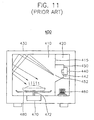
- FIG. 11 shows a conventional microwave oven 400.
- conventional microwave oven 400 has a cabinet 430.
- Cabinet 430 includes a cooking cavity 410 and a control chamber 420 which are separated from each other by a partition 415.
- a wave guide 450 which guides high frequency microwaves generated from a magnetron 440 into cooking cavity 410 is attached to a predetermined position on partition 415. Magnetron 440 is coupled to a side of wave guide 450. In order to radiate the high frequency microwaves into cooking cavity 410, an aperture 452 is formed at a predetermined position in partition 415. In addition, an antenna 442 for sending the high frequency microwaves is integrally formed at a side of magnetron 440.
- a transformer 460 for generating a high voltage is mounted on a lower wall of control chamber 420.
- Transformer 460 is connected to magnetron 440 so as to apply the high-voltage to magnetron 440.
- a cooking tray 480 on which the foodstuffs to be heated are placed, is provided in cooking cavity 410.
- cooking tray 480 is coupled to a shaft 472 of a motor 470, and is rotated while the foodstuffs are being heated.
- Microwave oven 400 having the above described structure operates as follows.
- a microcomputer installed in microwave oven 400 sends an operating signal to transformer 460.
- transformer 460 generates the high voltage and transfers the high voltage to magnetron 440 so that the high frequency microwaves are generated by magnetron 440.
- the high frequency microwaves are radiated into cooking cavity 410 through antenna 442, wave guide 450, and aperture 452 so the foodstuffs placed on cooking tray 480 are heated.
- the microcomputer sends an operating signal to motor 470 so as to rotate cooking tray 480 while the foodstuffs are being heated.
- conventional microwave oven 400 having the above mentioned structure has a disadvantage in that the microwaves are not uniformly distributed in cooking cavity 410, so the microwaves penetrate into the foodstuffs to be heated to a limited depth. For this reason, when a large amount of the foodstuffs are placed on cooking tray 480, the microwaves do not reach a portion of the foodstuffs, so the foodstuffs are not uniformly heated.
- the microwave oven requires a sufficient stirring of the foodstuffs in order to uniformly heat the foodstuffs. Moreover, such stirring is difficult when the foodstuffs to be heated are fragile.
- U.S. patent No. 4,937,418 issued to Boulard discloses a microwave oven which distributes the temperature inside the cooking cavity uniformly while minimizing the stirring of the foodstuffs.
- Boulard's microwave oven has a wave spreader including a wave guide.
- the wave guide has at least one wave-receiving opening formed at an upper portion thereof and at least one wave-diffusing opening formed at a lower portion thereof.
- First and second deflectors for deflecting microwaves are provided in the wave guide.
- Boulard's wave spreader is provided as a separate device and installed in the cooking cavity, so the useable volume of the cooking cavity is reduced.
- U.S. patent No. 5,698,128 issued to Sakai discloses a microwave oven in which projections are formed in the cooking cavity.
- a plurality of convex projections of different sizes are formed in the cooking cavity so as to uniformly distribute the microwaves radiated into the cooking cavity.
- forming the projections in the cooking cavity is difficult and the microwaves are not properly distributed in the cooking cavity if the convex projections are insufficiently provided in the cooking cavity.
- the present invention has been made to solve the problems of the prior arts, and accordingly, it is an object of the present invention to provide a microwave oven which can uniformly distribute microwaves in horizontal and vertical directions within a cooking cavity, and which can be easily manufactured with simple structure.
- FIG. 1 shows a microwave oven 100 according to the preferred embodiment of the present invention.
- microwave oven 100 has a cabinet 130.
- Cabinet 130 includes a cooking cavity 110 and a control chamber 120 which are separated from each other by a first side wall 115.
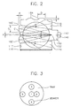
- Cooking cavity 110 is defined by an upper wall 111, a bottom wall 112, a door 116 (shown in FIG. 2) installed at a front of microwave oven 100, a first side wall 115, a second side wall 117 positioned opposite to first side wall 115, and a third side wall 118 positioned opposite to door 116.
- a wave guide 150 which guides a microwave generated from a magnetron 140 into cooking cavity 110 is attached to a rear side of first side wall 115.
- First side wall 115 is formed at its predetermined position corresponding to wave guide 150 with a microwave outlet 152 so as to allow the microwave to be radiated into cooking cavity 110.
- Magnetron 140 is assembled to one side of wave guide 150.
- An antenna 142 for transmitting the microwave to wave guide 150 is integrally formed with magnetron 140.
- a transformer 160 for generating a high-voltage is mounted on a bottom wall of control chamber 120. Transformer 160 is connected to magnetron 140 so as to apply the high-voltage to magnetron 140.
- a cooking tray 180 on which foodstuffs 186 to be heated are placed, is provided in cooking cavity 110.
- cooking tray 180 is connected to a motor 170 through a shaft 172 and rotates while the foodstuffs are being heated.
- second side wall 117 is formed with at least one first arcuate concave portion 182 and third side wall 118 is formed with at least one second arcuate concave portion 184.
- second and third side walls 117 and 118 are formed with two arcuate concave portions, respectively, which are spaced apart from each other by a predetermined distance.
- the upper wall is formed with at least one arcuate concave portion.
- a distance between two arcuate concave portions is formed in the range of a quarter wavelength to a half wavelength of the microwave.
- each arcuate concave portion has a diameter D larger than a half wavelength of the microwave. More preferably, the diameter of the arcuate concave portion is in the range of 70 to 100mm. Within this range, first and second arcuate concave portions 182 and 184 can have different diameters from each other.
- a distance L between a center C of each arcuate concave portion 182 formed at second side wall 117 and the bottom wall is larger than a half wavelength of the microwave. According to the preferred embodiment of the present invention, distance L is larger than 60mm. Also, a depth d of the arcuate concave portion is in a range of 3 to 24mm. Within this range, first and second arcuate concave portions can have different depths from each other.
- a center C between two arcuate concave portions 182 formed at second side wall 117 is in line with or is offset by a predetermined distance from a center of microwave outlet 152. If center C between two arcuate concave portions 182 is offset from the center of microwave outlet 152, an offset distance l is shorter than an eighth wavelength of the microwave. That is, when viewed from the top, center C between two arcuate concave portions 182 formed at second side wall 117 is offset less than 15mm from the center of microwave outlet 152.
- a distance between a lower end of microwave outlet 152 and bottom wall 112 of cavity 110 is larger than a half wavelength of the microwave.
- FIG. 9 shows an arcuate concave portion 282 according to another embodiment of the present invention.
- arcuate concave portion 282 is formed at a front edge thereof with a rim portion 284 having a diameter identical to the diameter of arcuate concave portion 282.
- a width t of rim portion 284 is larger than 1mm.
- FIG. 10 shows an arcuate concave portion 382 according to still another embodiment of the present invention.
- Arcuate concave portion 382 is formed at a front edge thereof with a rim portion 384 having a diameter larger than the diameter of arcuate concave portion 382.
- a radius of rim portion 384 is larger than the diameter of arcuate concave portion 382 by approximately 1mm and a width t thereof is larger than 1mm.
- Microwave oven 100 having the above mentioned structure operates as follows.
- a microcomputer installed in microwave oven 100 sends an operating signal to transformer 160.
- transformer 160 Upon receiving the operating signal, transformer 160 generates a high voltage and transmits the high voltage to magnetron 140 so that the high-frequency microwaves are generated by magnetron 140.
- the high-frequency microwaves are radiated into cooking cavity 110 through antenna 142, wave guide 150 and microwave outlet 152.
- positions, shapes and sizes of arcuate concave portions 182 and 184 must be properly determined.
- the inventor of the present invention has carried out several geometrical experiments for creating optimal hot spots in cooking cavity 110 and found optimal positions, shapes and sizes of arcuate concave portions 182 and 184. According to the inventor's experiments, the microwaves are uniformly distributed in vertical and horizontal directions in cooking cavity 110 by forming arcuate concave portions 182 and 184 having positions, shapes and sizes as mentioned above.
- test samples 1 to 5 were arranged on the cooking tray as shown in FIG. 3. Beakers having water therein were used as test samples. Tables 1 and 2 show the results tested by a conventional microwave oven and the microwave oven of the present invention, respectively. Result tested by the conventional microwave oven.
- FIGs. 4 and 5 are graphs showing the above results.
- a temperature difference w between a sample 1 having minimum ⁇ T and a sample 4 having maximum ⁇ T was 9.2°.
- the temperature difference w between a sample 2 having minimum ⁇ T and a sample 4 having maximum ⁇ T was 4.5°. Accordingly, it is understood that the microwave oven of the present invention can uniformly heat the foodstuffs horizontally.
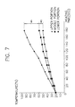
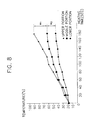
- Tables 3 and 4 show the results tested by a conventional microwave oven and the microwave oven of the present invention, respectively. Result tested by the conventional microwave oven. Position ⁇ time(sec) 0 20 40 60 80 100 120 140 160 180 upper 19.1 22.9 27.9 31.9 35.7 39.4 42.3 45.6 46.9 49.3 middle 19.0 24.7 30.0 34.5 39.7 44.2 48.7 51.8 54.1 57.7 lower 19.2 28.9 37.5 45.3 54.4 61.2 70.9 78.4 85.8 93.6 Result tested by the microwave oven of the present invention.
- FIGs. 7 and 8 are graphs showing the above results.
- a temperature difference w 1 between upper and middle portions of the milk bottle was larger than a temperature difference w 2 between middle and lower portions of the milk bottle.
- temperature difference w 1 between upper and middle portions of the milk bottle is similar to temperature difference w 2 between middle and lower portions of the milk bottle. Accordingly, it is understood that the microwave oven of the present invention can uniformly heat the foodstuffs vertically.
- the microwave oven according to the present invention can uniformly penetrate the microwaves through the foodstuffs in vertical and horizontal directions thereof so that the heating efficiency to the foodstuffs is improved and the heating time thereof is reduced.
- arcuate concave portions have simple shapes, manufacturing work thereof is easy and the manufacturing cost thereof is reduced.
Landscapes
- Physics & Mathematics (AREA)
- Electromagnetism (AREA)
- Engineering & Computer Science (AREA)
- Power Engineering (AREA)
- Constitution Of High-Frequency Heating (AREA)
- Electric Ovens (AREA)
Claims (15)
- Four à micro-ondes (100) qui comprend un habillage (130) ayant une cavité de cuisson (110) pour recevoir des aliments à chauffer, et une chambre de commande (120) séparée de la cavité de cuisson (110) par une cloison, une porte (116) installée sur une face avant de l'habillage (130) pour ouvrir et fermer la cavité de cuisson (110), un magnétron (140) installé dans la chambre de commande (120) pour produire une micro-onde, et un guide d'ondes (150) pour guider dans la cavité de cuisson (110) la micro-onde produite par le magnétron (140), la cavité de cuisson (110) étant délimitée par une paroi supérieure (111), une paroi inférieure (112), une première paroi latérale (115) sur laquelle est attaché le guide d'ondes (150), une seconde paroi latérale (117) qui fait face à la première paroi latérale (115), la porte (116), et une troisième paroi latérale (118) qui fait face à la porte (116), la première paroi latérale (115) étant formée avec une sortie (152) pour la micro-onde, caractérisé en ce que les seconde et troisième parois latérales (117 et 118) sont respectivement formées avec deux parties en forme d'arc concave (182 et 184) séparées l'une de l'autre selon une distance prédéterminée pour distribuer les micro-ondes.
- Four à micro-ondes (100) selon la revendication 1, caractérisé en ce que le diamètre (D) de chaque partie en forme d'arc concave est plus grand qu'une demi-longueur d'onde de la micro-onde.
- Four à micro-ondes (100) selon l'une quelconque des revendications 1 ou 2, caractérisé en ce que chaque partie concave a un diamètre compris entre 30 et 100 mm.
- Four à micro-ondes (100) selon l'une quelconque des revendications 1 à 3, caractérisé en ce qu'une distance (C) comprise entre un centre de chaque partie en forme d'arc concave (182) formée au niveau de la seconde paroi latérale (117) et de la paroi inférieure (112) est plus grande qu'une demi-longueur d'onde de la micro-onde.
- Four à micro-ondes (100) selon l'une quelconque des revendications 1 à 3, caractérisé en ce qu'une distance (L) entre un centre de chaque partie en forme d'arc concave (182) formée au niveau de la seconde paroi latérale (117) et de la paroi inférieure (112) est supérieure à 60 mm.
- Four à micro-ondes (100) selon l'une quelconque des revendications 1 à 5, caractérisé en ce que la profondeur (d) de chaque partie en forme d'arc concave est comprise entre 3 et 24 mm.
- Four à micro-ondes (100) selon l'une quelconque des revendications 1 à 6, caractérisé en ce que, lorsque vu de dessus, un premier centre (C) compris entre deux parties en forme d'arc concave (182) formées au niveau de la seconde paroi latérale (117) est aligné avec un second centre de la sortie (152) de la micro-onde.
- Four à micro-ondes (100) selon l'une quelconque des revendications 1 à 6, caractérisé en ce que, lorsque vu de dessus, un premier centre (C) compris entre deux parties en forme d'arc concave (182) formées au niveau de la seconde paroi latérale (117) est décalé de moins d'un huitième de longueur d'onde de la micro-onde relativement à un second centre de la sortie (152) de la micro-onde.
- Four à micro-ondes (100) selon l'une quelconque des revendications 1 à 6, caractérisé en ce que, lorsque vu de dessus, un premier centre compris entre deux parties en forme d'arc concave (182) formées au niveau de la seconde paroi latérale (117) est décalé de moins de 15 mm relativement à un second centre de la sortie (152) de la micro-onde.
- Four à micro-ondes (100) selon l'une quelconque des revendications 1 à 9, caractérisé en ce qu'une partie formant jante (284) dont la profondeur excède 1 mm est formée sur un bord antérieur de chaque partie en forme d'arc concave (282)
- Four à micro-ondes (100) selon la revendication 1, caractérisé en ce qu'une distance entre deux parties en forme d'arc concave (182) formées au niveau de la seconde paroi latérale (117) est dans une plage comprise entre un quart et une moitié de la longueur d'onde de la micro-onde.
- Four à micro-ondes (100) selon l'une quelconque des revendications 1 à 11, caractérisé en ce qu'une distance comprise entre une extrémité inférieure de la sortie (152) de la micro-onde et la paroi inférieure (112) de la cavité (110) est supérieure à une demi-longueur d'onde de la micro-onde.
- Four à micro-ondes (100) selon la revendication 1, caractérisé en ce que le diamètre (D) de chaque partie en forme d'arc concave (182) est plus grand qu'une demi-longueur d'onde de la micro-onde, une distance (L) entre un premier centre de chaque partie en forme d'arc concave (182) formée au niveau de la seconde paroi latérale (117) et de la paroi inférieure (112) est supérieure à une demi-longueur d'onde de la micro-onde, chaque partie en forme d'arc concave (182) a une profondeur (d) comprise dans une plage de 3 à 24 mm et, lorsque vu de dessus, un second centre entre deux parties en forme d'arc concave (182) formées au niveau de la seconde paroi latérale (117) est aligné avec un troisième centre de la sortie (152) de la micro-onde.
- Four à micro-ondes (100) selon la revendication 1, caractérisé en ce que le diamètre (D) de chaque partie en forme d'arc concave (182) est compris entre 30 et 100 mm, une première distance entre un premier centre (C) de chaque partie en forme d'arc concave (182) formée au niveau de la seconde paroi latérale (117) et de la paroi inférieure (112) est supérieure à 60 mm, chaque partie en forme d'arc concave (182) a une profondeur comprise dans la plage de 3 à 24 mm et, lorsque vu de dessus, un second centre compris entre deux parties en forme d'arc concave (182) formées au niveau de la seconde paroi latérale (117) est décalé de moins de 15 mm relativement à un troisième centre de la sortie (152) de la micro-onde.
- Four à micro-ondes (100) selon la revendication 14, caractérisé en ce qu'une seconde distance entre deux parties en forme d'arc concave (182) formées au niveau de la seconde paroi latérale (117) est comprise dans une plage d'un quart à une demi-longueur d'onde de la micro-onde, et une troisième distance entre une extrémité inférieure de la sortie (152) de la micro-onde et la paroi inférieure (112) de la cavité (110) est supérieure à une demi-longueur d'onde de la micro-onde.
Priority Applications (2)
| Application Number | Priority Date | Filing Date | Title |
|---|---|---|---|
| DE1998632588 DE69832588T2 (de) | 1998-04-11 | 1998-04-11 | Mikrowellenherd mit kreisförmigen konkave Portionen in einem Hohlraum zum Verteilen der Mikrowellen |
| EP19980106683 EP0949848B1 (fr) | 1998-04-11 | 1998-04-11 | Four à micro-ondes comportant dans une cavité des portions concaves circulaires pour distribuer les micro-ondes |
Applications Claiming Priority (1)
| Application Number | Priority Date | Filing Date | Title |
|---|---|---|---|
| EP19980106683 EP0949848B1 (fr) | 1998-04-11 | 1998-04-11 | Four à micro-ondes comportant dans une cavité des portions concaves circulaires pour distribuer les micro-ondes |
Publications (2)
| Publication Number | Publication Date |
|---|---|
| EP0949848A1 EP0949848A1 (fr) | 1999-10-13 |
| EP0949848B1 true EP0949848B1 (fr) | 2005-11-30 |
Family
ID=8231754
Family Applications (1)
| Application Number | Title | Priority Date | Filing Date |
|---|---|---|---|
| EP19980106683 Expired - Lifetime EP0949848B1 (fr) | 1998-04-11 | 1998-04-11 | Four à micro-ondes comportant dans une cavité des portions concaves circulaires pour distribuer les micro-ondes |
Country Status (2)
| Country | Link |
|---|---|
| EP (1) | EP0949848B1 (fr) |
| DE (1) | DE69832588T2 (fr) |
Family Cites Families (7)
| Publication number | Priority date | Publication date | Assignee | Title |
|---|---|---|---|---|
| CH369836A (de) * | 1959-07-15 | 1963-06-15 | Therma Ag | Vorrichtung zur Erwärmung von Stoffen mittels Hochfrequenzenergie |
| DE1515156A1 (de) * | 1964-07-03 | 1969-07-03 | Siemens Elektrogeraete Gmbh | Garraum eines HF-Strahlungsherdes |
| US3461260A (en) * | 1966-05-16 | 1969-08-12 | Gen Motors Corp | Microwave oven |
| SE458493B (sv) * | 1987-01-08 | 1989-04-03 | Philips Norden Ab | Mikrovaagsugn |
| JPH06196257A (ja) * | 1992-12-24 | 1994-07-15 | Hitachi Ltd | 電子レンジ |
| DE4313806A1 (de) * | 1993-04-27 | 1994-11-03 | Rene Salina | Vorrichtung zum Erhitzen von Materialien in einer mit Mikrowellen bestrahlbaren Heizkammer und Verfahren zum Herstellen von keramischem Gut, bei dem das Rohgut mittels Mikrowellen getrocknet wird |
| JP3317071B2 (ja) * | 1995-02-09 | 2002-08-19 | タイガー魔法瓶株式会社 | 高周波加熱装置 |
-
1998
- 1998-04-11 EP EP19980106683 patent/EP0949848B1/fr not_active Expired - Lifetime
- 1998-04-11 DE DE1998632588 patent/DE69832588T2/de not_active Expired - Lifetime
Also Published As
| Publication number | Publication date |
|---|---|
| DE69832588T2 (de) | 2006-08-10 |
| EP0949848A1 (fr) | 1999-10-13 |
| DE69832588D1 (de) | 2006-01-05 |
Similar Documents
| Publication | Publication Date | Title |
|---|---|---|
| CA1050121A (fr) | Four a micro-ondes avec emission en mode de surface | |
| CA2096893C (fr) | Guide d'ondes pour four a micro-ondes | |
| US6008483A (en) | Apparatus for supplying microwave energy to a cavity | |
| US5698128A (en) | Microwave oven with a projection for uniform heating within the cavity | |
| CA1197565A (fr) | Four a micro-ondes avec systeme d'excitation a double alimentation | |
| US5742033A (en) | Wave guide having an improved structure used in a microwave oven | |
| US5990466A (en) | Apparatus for supplying microwave energy to a cavity | |
| US5919391A (en) | Microwave oven having arcuate concave portions in a cavity for distributing microwaves | |
| KR100448541B1 (ko) | 전자렌지 | |
| CA1193326A (fr) | Four a microondes avec antenne rotative | |
| KR20000023782A (ko) | 쿡킹용 전기 오븐 | |
| WO1997047161A2 (fr) | Appareil de chauffage a micro-ondes | |
| EP0949848A1 (fr) | Four à micro-ondes comportant dans une cavité des portions concaves circulaires pour distribuer les micro-ondes | |
| US5786579A (en) | Microwave oven waveguide with mode transducer and differential mode absorber | |
| KR100311271B1 (ko) | 파분산용 호형 오목부가 캐비티내에 구비된 전자렌지 | |
| KR20040059143A (ko) | 전자렌지 | |
| JPH11311418A (ja) | 電子レンジ | |
| JP3819618B2 (ja) | 高周波加熱装置 | |
| KR0127653Y1 (ko) | 고주파 가열장치 | |
| JP3966110B2 (ja) | マイクロ波加熱装置 | |
| JP2000179864A (ja) | 高周波加熱装置 | |
| GB2119210A (en) | Microwave oven with rotary antennas | |
| JPS6250953B2 (fr) | ||
| KR20000009622A (ko) | 마이크로파 조절 기능을 가지는 전자레인지 | |
| JPH07158860A (ja) | 電子レンジ |
Legal Events
| Date | Code | Title | Description |
|---|---|---|---|
| PUAI | Public reference made under article 153(3) epc to a published international application that has entered the european phase |
Free format text: ORIGINAL CODE: 0009012 |
|
| AK | Designated contracting states |
Kind code of ref document: A1 Designated state(s): DE FR GB IT |
|
| AX | Request for extension of the european patent |
Free format text: AL;LT;LV;MK;RO;SI |
|
| 17P | Request for examination filed |
Effective date: 20000404 |
|
| AKX | Designation fees paid |
Free format text: DE FR GB IT |
|
| RAP1 | Party data changed (applicant data changed or rights of an application transferred) |
Owner name: DAEWOO ELECTRONICS CORPORATION |
|
| 17Q | First examination report despatched |
Effective date: 20050208 |
|
| GRAP | Despatch of communication of intention to grant a patent |
Free format text: ORIGINAL CODE: EPIDOSNIGR1 |
|
| GRAS | Grant fee paid |
Free format text: ORIGINAL CODE: EPIDOSNIGR3 |
|
| GRAA | (expected) grant |
Free format text: ORIGINAL CODE: 0009210 |
|
| AK | Designated contracting states |
Kind code of ref document: B1 Designated state(s): DE FR GB IT |
|
| REG | Reference to a national code |
Ref country code: GB Ref legal event code: FG4D |
|
| REF | Corresponds to: |
Ref document number: 69832588 Country of ref document: DE Date of ref document: 20060105 Kind code of ref document: P |
|
| ET | Fr: translation filed | ||
| PLBE | No opposition filed within time limit |
Free format text: ORIGINAL CODE: 0009261 |
|
| STAA | Information on the status of an ep patent application or granted ep patent |
Free format text: STATUS: NO OPPOSITION FILED WITHIN TIME LIMIT |
|
| 26N | No opposition filed |
Effective date: 20060831 |
|
| PGFP | Annual fee paid to national office [announced via postgrant information from national office to epo] |
Ref country code: IT Payment date: 20120319 Year of fee payment: 15 |
|
| PGFP | Annual fee paid to national office [announced via postgrant information from national office to epo] |
Ref country code: FR Payment date: 20130408 Year of fee payment: 16 Ref country code: GB Payment date: 20130318 Year of fee payment: 16 |
|
| PGFP | Annual fee paid to national office [announced via postgrant information from national office to epo] |
Ref country code: DE Payment date: 20140430 Year of fee payment: 17 |
|
| GBPC | Gb: european patent ceased through non-payment of renewal fee |
Effective date: 20140411 |
|
| REG | Reference to a national code |
Ref country code: FR Ref legal event code: ST Effective date: 20141231 |
|
| PG25 | Lapsed in a contracting state [announced via postgrant information from national office to epo] |
Ref country code: GB Free format text: LAPSE BECAUSE OF NON-PAYMENT OF DUE FEES Effective date: 20140411 |
|
| PG25 | Lapsed in a contracting state [announced via postgrant information from national office to epo] |
Ref country code: FR Free format text: LAPSE BECAUSE OF NON-PAYMENT OF DUE FEES Effective date: 20140430 |
|
| PG25 | Lapsed in a contracting state [announced via postgrant information from national office to epo] |
Ref country code: IT Free format text: LAPSE BECAUSE OF NON-PAYMENT OF DUE FEES Effective date: 20140411 |
|
| REG | Reference to a national code |
Ref country code: DE Ref legal event code: R119 Ref document number: 69832588 Country of ref document: DE |
|
| PG25 | Lapsed in a contracting state [announced via postgrant information from national office to epo] |
Ref country code: DE Free format text: LAPSE BECAUSE OF NON-PAYMENT OF DUE FEES Effective date: 20151103 |