EP0949879B1 - Duschtüreinheit - Google Patents
Duschtüreinheit Download PDFInfo
- Publication number
- EP0949879B1 EP0949879B1 EP97913913A EP97913913A EP0949879B1 EP 0949879 B1 EP0949879 B1 EP 0949879B1 EP 97913913 A EP97913913 A EP 97913913A EP 97913913 A EP97913913 A EP 97913913A EP 0949879 B1 EP0949879 B1 EP 0949879B1
- Authority
- EP
- European Patent Office
- Prior art keywords
- panel
- door unit
- camming
- rollers
- roller
- Prior art date
- Legal status (The legal status is an assumption and is not a legal conclusion. Google has not performed a legal analysis and makes no representation as to the accuracy of the status listed.)
- Expired - Lifetime
Links
Images




Classifications
-
- A—HUMAN NECESSITIES
- A47—FURNITURE; DOMESTIC ARTICLES OR APPLIANCES; COFFEE MILLS; SPICE MILLS; SUCTION CLEANERS IN GENERAL
- A47K—SANITARY EQUIPMENT; ACCESSORIES THEREFOR, e.g. TOILET ACCESSORIES
- A47K3/00—Baths; Showers; Appurtenances therefor
- A47K3/28—Showers or bathing douches
- A47K3/30—Screens or collapsible cabinets for showers or baths
- A47K3/36—Articulated screens
- A47K3/362—Articulated screens comprising sliding and articulated panels
Definitions
- This invention relates to bathing door units for bathing fixtures such as showers and bathtubs. More particularly it provides a pivotable and extendable bathing door unit that requires no overhead support yet affords a simplified and stable extension of a slidable panel.
- U.S. patent 5,417,272 there is disclosed in one embodiment a wall mounted bathroom panel assembly where a slidable panel operates in conjunction with a pivotal panel.
- This assembly provides the desired open access.
- the sliding action between the pivotal and sliding panel is effected by rollers and roller tracks mounted in both the pivotal and slidable panels for reciprocal engagement.
- This arrangement poses problems in that when the slidable panel is fully extended an undesired rocking can take place.
- This arrangement also makes the adjustment of the doors relative to one another difficult.
- a multiple bracket and roller structure is required with brackets and rollers as well as roller tracks provided in both tracks connected to upper and lower portions of each panel.
- U.S. patent 4,276,919 discloses rollers arranged in a tandem relationship for a shower door but not one having a pivotal and slidable door. Thus, a need exists for an improved bathing door unit.
- German patent DE 29618205 discloses a shower screen having a fixed wall section and a wall section movable via a roller mounted between a lower fixed rail and a movable rail.
- the shower screen disclosed therein is not pivotal.
- both wall sections of the German reference have roller rails.
- EP 0541877 discloses a bath screen comprising a pivotal panel available to adjustment such that it is plumb with an adjacent surface, providing enhanced sealing capabilities.
- the bath screen disclosed in this reference does not provide for an extendible rail panel.
- the invention provides a pivotal and extendable bathing door unit wherein a first panel is adapted to be pivotally connected to a supporting wall, the first panel having a roller bracket at the upper and lower ends thereof.
- a second panel is adapted to be extendably connected to said first panel, the second panel having a roller track at the upper and lower ends thereof.
- First and second rollers are connected to each said roller bracket with said rollers of the upper bracket of the first panel being suitable to ride in the upper track of the second panel and the rollers of the lower bracket of the first panel being suitable to ride in the lower track of the second panel, the second panel being devoid of any roller brackets or rollers.
- roller brackets there are adjustment means operatively associated with the roller brackets for vertically positioning said rollers relative to said tracks.
- roller stop members connected to the second panel for contacting the roller brackets to thereby limit extension of the second panel.
- first and second panels are secured to discontinuous frame structures.
- camming means operatively associated with both the upper and lower ends of a support for the first panel to provide a lifting and stop action as well as guidance for the first panel upon rotation thereof.
- the bathing door units of this invention are shown generally at 10 and 10A in conjunction with the bathing facility 12 having a tub 13, side walls 11 and 15 and a shower head 14.
- Each of the units 10 and 10A have the same components with those of unit 10A designed by the same reference numeral followed by the letter "A". The difference is in the orientation of the panels generally 17, 19 and 17A and 19A. This is seen in conjunction with Fig. 3 where the bathing units 10 and 10a are shown in an extended or closed position with respect to the bathing facility 12.
- each of the bathing door units as represented by unit generally 10 is composed of two panel members 16 and 18 with panel member 16 being a slidable panel and 18 being a pivotable panel member such as will be better understood as the description proceeds.
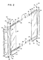
- Panel generally 17 includes panel member 18 as well as a top frame 20 and a bottom frame 21.
- panel generally 19 also has similar top and bottom frames 23 and 24, respectively, secured to the top and bottom of panel member 16.
- Frames 23 and 24 have roller tracks such as 28, whereas frames 20 and 21 do not.
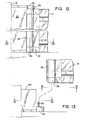
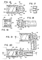
- pivot column 26 Positioned along the side of panel member 18 is a pivot column 26 which has a pivot bushing 35 connected thereto at its lower end by the screw 34. Pivot bushing 35 is adapted to be engaged by the projection 36 of the pivot block 38 which is attached to the expander jamb 29 also by the screws 34. It should be further noted that attached to the top of the expander jamb 29 is the same pivot block 38 for engagement with pivot bushing 35 which is secured to the bottom of the column 26. This will be more fully explained later in conjunction with Figs. 12-23. Expander jamb 29 is in turn attached to a wall jamb 30 by the screws 34. Wall jamb 30 is secured to the wall such as 15 (see Figs. 1 and 3).
- roller brackets 43 and 44 attached to the ends of top and bottom frames 20 and 21, respectively, of panel 17 by means of the screws 45.
- Rollers 46 are rotatably mounted on the brackets 43 by means of the arms such as 70 shown in Fig. 5 and ride in tracks 28 of panel 19.
- Suitable end caps 48 engage the roller brackets 43.
- Attached to the undersides of frames 21 and 24 are seals 57.
- Secured to the end of panel member 19 is a handle 59 enclosed at opposite ends by end caps 61 and retained by screws 34. Handle 59 has attached thereto a magnet 64.
- panel 19A also has a handle 59A attached to panel 19 which will also have a magnet such as 64 connected thereto.
- This construction affords a releasable but retentive closure of the bathing door units 10 and 10A as also seen in Fig. 3.
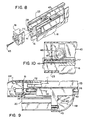
- Figs. 4-7 illustrate the roller bracket 43 and the positioning of the rollers 46 in the track 28 of the panel 19.
- Bracket member 43 has elongated arms 70 to which are attached the rollers 46 by means of the shafts 47 of screws 42 which are held in a nonrotatable manner by lock nuts 72 (See Figs. 5, 7 and 9).
- the bracket member 43 is attached to the end of top frame 20 by the screws such as 45 passing through the slots 78 of the bracket member 43 and into grooves 79 of frame 20. This is best seen in Fig. 6. All of the frame extrusions have slots such as shown at 41 in Fig. 8 for receiving the panel members such as 16 and 18.
- the panel members have been secured therein by a suitable adhesive compound, such as the structural adhesive sold under the trademark LOCTITE Product 324 and the solventless activator sold under the trademark LOCTITE Product 7380, both available from the Loctite Corporation in Newington, Connecticut, or by suitable screw and hole connections.
- a suitable adhesive compound such as the structural adhesive sold under the trademark LOCTITE Product 324 and the solventless activator sold under the trademark LOCTITE Product 7380, both available from the Loctite Corporation in Newington, Connecticut, or by suitable screw and hole connections.
- Bracket 43 positions rollers 46 in the roller track 28 of top frame 20. Extending from arm 74 is flange 80 having the slots 68 and 78 for screws 45. It will be appreciated that the same positioning of the rollers 46 from the bracket 43 will prevail at the bottom ends of the panel 17 for positioning the rollers in the roller track 28 of frame 24 of panel 19, as seen in Fig. 2.
- Figs. 4 and 7 illustrate the adjustment feature of upper roller bracket 43 and top frame 20 of panel 17. This is afforded by a threaded adjustment passage 97 extending through flange portion 80 of the bracket 43 with passage 97 accommodating screw 98. Adjustment of the position of bracket 43 and roller 46 against track 28 in frame 23 is effected by loosening screws 45 and 44 and turning adjustment screw 98 in threaded passage 97. When the desired adjustment is made, screws 45 and 44 are retightened.
- stop member 81 which is attached to top frame 23 of rolling panel 19 by the screw 45 and the slot 77 in frame 23.
- Stop member 81 has a protruding portion 82 which provides an extension of track 28, as well as a contact surface 50 for contact with an end surface 69 of bracket flange 73. This feature avoids contact with the roller 46 when rolling panel is in an extended position as seen in Fig. 3. It will also be appreciated that stop member 81 is also positioned at the bottom of panel 19 and is connected to bottom frame 24 for a similar purpose. End caps 48 are also attached to the stop member 81.
- a pivot bushing 35 is attached to the pivot column 26 by screw 85 fastened to the underside of column 26, and a similar bushing 35 is connected to the top.
- Pivot bushings 35 engage pivot blocks 38.
- Pivot block 38 includes a connector section 83 and a camming section 84.
- Two stabilizing flanges 65 and 66 extend upwardly from a base 88 for engagement with expander jamb 29.
- This raising motion affords a distance between the panel members 17 and 19 and the upper edge of a bathing facility such as tub 13 to afford easy cleaning.
- a sufficient distance is provided between the similar camming surfaces of pivot bushing 35 and pivot block 38 at the top of wall jamb 30 to afford the lifting action.
- the pivoting action is guided by the annular wall 60 extending from camming section 84 and riding in annular groove 62 of camming section 91.
- a post member 94 with an extending stop member 95 extending upwardly from camming section 84. This affords a stop for panel 17 when contact is made with stop member 96 of pivot bushing 35. This is illustrated in Fig. 21 when the panel 17 is in a raised position. It will be noted that the stop members 95 and 96 also engage when panel 17 is moved in a 180° position from that shown in Fig. 21.
- the stop member 36 extending from pivot block 38 will maintain contact with the inner annular surface 95 of pivot bushing 31. This is accomplished by having stop member 95 positioned adjacent expander jamb 29 in a 9 o'clock position and is illustrated in Figs. 24 and 25.
- stop members 95 and 96 Yet another unexpected feature is the simplified camming and stop feature as represented by stop members 95 and 96. This affords a positive stop in two directions. The use of the same camming members at the top and bottom of the door unit reduces costs of parts and assembly.
- panel members 16 and 18 are surrounded on three of their sides with frame structures such as top frame 20 and bottom frame 21 and pivot column 26 with respect to panel 16 and top and bottom frames 23 and 24 and handle 59 with respect to panel 18.
Landscapes
- Health & Medical Sciences (AREA)
- Public Health (AREA)
- Epidemiology (AREA)
- General Health & Medical Sciences (AREA)
- Devices For Medical Bathing And Washing (AREA)
- Residential Or Office Buildings (AREA)
- Extensible Doors And Revolving Doors (AREA)
Claims (10)
- Drehbare und ausziehbare Duschtüreinheit (10, 10A), die folgendes umfasst:ein erstes Feld (17, 17A), das drehbar mit einer Trägerwand (15) verbunden ist, wobei das genannte erste Feld (17, 17A) einen Rollenträger (43) an den oberen und unteren Enden des Felds aufweist;ein zweites Feld (19, 19A), das ausziehbar mit dem genannten ersten Feld (17, 17A) verbunden werden kann, wobei das genannte zweite Feld eine Rollenspur (28) an den oberen und unteren Enden des Felds aufweist; underste und zweite Rollen (46), die mit jedem der genannten Rollenträger (43) verbunden sind, wobei sich die genannten Rollen (46) des oberen Trägers (43) des ersten Felds (17, 17A) dazu eignen, in der oberen Spur (28) des zweiten Felds (19, 19A) zu laufen, und wobei sich die Rollen (46) des unteren Trägers (43) des ersten Felds (17, 17A) dazu eignen, in der unteren Spur des zweiten Felds (19, 19A) zu laufen, wobei die genannte Duschtüreinheit (10, 10A) dadurch gekennzeichnet ist, dass das genannte zweite Feld (19, 19A) frei von allen Rollenträgern oder Rollen ist.
- Türeinheit (10, 10A) nach Anspruch 1, dadurch gekennzeichnet, dass mindestens einer der genannten Rollenträger (43) eine Einstellungseinrichtung zur Positionierung der genannten Rollen im Verhältnis zu den genannten Spuren (28) aufweist.
- Türeinheit (10, 10A) nach Anspruch 1, gekennzeichnet durch Rollenstoppelemente (81), die mit dem genannten zweiten Feld (19, 19A) verbunden sind, so dass sie eine der Rollen (46) berühren, um dadurch die Extension des zweiten Felds (19, 19A) einzuschränken.
- Türeinheit (10, 10A) nach Anspruch 1, dadurch gekennzeichnet, dass das genannte erste Feld (17, 17A) und das genannte zweite Feld (19, 19A) an unterbrochenen Rahmenstrukturen angebracht sind.
- Türeinheit (10, 10A) nach Anspruch 4, dadurch gekennzeichnet, dass die genannten Rahmenstrukturen eine dreiseitige Konfiguration aufweisen.
- Türeinheit (10, 10A) nach Anspruch 1, gekennzeichnet durch eine Nockeneinrichtung, die funktionsfähig einem unteren Ende eines Trägers (26) für das erste Feld (17, 17A) zugeordnet ist, um eine Hebewirkung des genannten ersten Felds (17, 17A) vorzusehen, wenn sich dieses dreht.
- Türeinheit (10, 10A) nach Anspruch 6, dadurch gekennzeichnet, dass die genannte Nockeneinrichtung ein erstes Nockenelement (84) und ein zweites Nockenelement (91) mit miteinander eingreifenden Anschlagoberflächen aufweist, um die Bewegung der genannten Nockeneinrichtung einzuschränken.
- Türeinheit (10, 10A) nach Anspruch 7, dadurch gekennzeichnet, dass die genannten Anschlagoberflächen durch eine Extension (36) eines Pfostenelements (94) definiert sind, das mit dem genannten ersten Nockenelement (84) verbunden ist und mit einem vorstehenden Element (96), das mit dem genannten Nockenelement (91) verbunden ist.
- Türeinheit (10, 10A) nach Anspruch 6, dadurch gekennzeichnet, dass eine zweite Nockeneinrichtung funktionsfähig einem oberen Ende des Trägers (26) für das erste Feld (17, 17A) zugeordnet ist, um für dieses eine Führung vorzusehen, wobei die genannte zweite Nockeneinrichtung ein erstes Nockenelement (84) und ein zweites Nockenelement (91) mit miteinander eingreifenden Anschlagoberflächen aufweist, wobei die genannten Nockenelemente zueinander Abstände aufweisen, um einen Eingriff während dem Drehen der Türeinheit (10, 10A) zu verhindern.
- Türeinheit (10, 10A) nach Anspruch 9, dadurch gekennzeichnet, dass die Anschlagoberflächen durch eine Extension (36) eines Pfostenelements (94) definiert sind, mit einer Verbindung mit einem der Nockenelemente (84, 91), und sich mit einer Extension in Kontakt mit einer Oberfläche (96) des anderen Nockenelements (84, 91).
Applications Claiming Priority (3)
| Application Number | Priority Date | Filing Date | Title |
|---|---|---|---|
| US08/739,646 US5908064A (en) | 1996-10-30 | 1996-10-30 | Bathing door unit |
| US739646 | 1996-10-30 | ||
| PCT/US1997/019773 WO1998018376A1 (en) | 1996-10-30 | 1997-10-29 | Bathing door unit |
Publications (2)
| Publication Number | Publication Date |
|---|---|
| EP0949879A1 EP0949879A1 (de) | 1999-10-20 |
| EP0949879B1 true EP0949879B1 (de) | 2002-06-19 |
Family
ID=24973223
Family Applications (1)
| Application Number | Title | Priority Date | Filing Date |
|---|---|---|---|
| EP97913913A Expired - Lifetime EP0949879B1 (de) | 1996-10-30 | 1997-10-29 | Duschtüreinheit |
Country Status (7)
| Country | Link |
|---|---|
| US (1) | US5908064A (de) |
| EP (1) | EP0949879B1 (de) |
| CN (1) | CN1130154C (de) |
| AU (1) | AU5097898A (de) |
| CA (1) | CA2270406C (de) |
| DE (1) | DE69713519T2 (de) |
| WO (1) | WO1998018376A1 (de) |
Families Citing this family (27)
| Publication number | Priority date | Publication date | Assignee | Title |
|---|---|---|---|---|
| US6068041A (en) * | 1998-08-01 | 2000-05-30 | Herman Miller Inc. | Adjustable partition assembly |
| SE523996C2 (sv) * | 2000-12-15 | 2004-06-15 | Glasmaesteribranschens Service | Anordning vid ett gångjärn |
| US6435253B1 (en) * | 2001-02-28 | 2002-08-20 | Smed International, Inc. | Extendible partition assembly |
| US6659155B1 (en) * | 2002-04-05 | 2003-12-09 | Freedom Door Company, Inc. | Bidirectional swinging screen door and frame assembly |
| US6643898B1 (en) | 2002-05-18 | 2003-11-11 | Southeastern Aluminum Products, Inc. | Self-centering pivot door hinge system |
| US7533502B2 (en) * | 2003-12-22 | 2009-05-19 | Luke Siegel | Room dividing system |
| US7607199B2 (en) | 2005-06-13 | 2009-10-27 | C.R. Laurence Company, Inc. | Frameless glass door hinge |
| US20090038070A1 (en) * | 2007-08-10 | 2009-02-12 | Maax Canada,Inc. | Shower door track |
| CN101543383B (zh) * | 2009-05-04 | 2015-11-25 | 倪既民 | 门闭式淋浴池浴两用浴缸 |
| US9062485B2 (en) * | 2009-07-07 | 2015-06-23 | Michael John Guidos | Articulating roller arm assembly |
| US20110024590A1 (en) * | 2009-07-28 | 2011-02-03 | Maax Bath Inc. | Hardware for Mounting Glass Panels or Similar Structures |
| US9492037B2 (en) * | 2009-10-23 | 2016-11-15 | Christopher M. Kee | Hybrid enclosure system |
| US8443549B2 (en) * | 2010-03-08 | 2013-05-21 | Stanley Black & Decker, Inc. | Sliding door with large opening |
| CA2752721C (en) * | 2010-09-17 | 2018-12-04 | Stanley Black & Decker, Inc. | Slide door |
| CA2831363A1 (en) * | 2011-05-12 | 2012-11-15 | Maliform Pty. Ltd. | Improvements in bathing fixtures |
| US9622623B2 (en) | 2011-07-19 | 2017-04-18 | Christopher Marshal KEE | Enclosure systems |
| ES2717227T3 (es) * | 2011-10-24 | 2019-06-19 | Laurence C R Co Inc | Conjunto de papnel de puerta corredera |
| US9163451B1 (en) * | 2012-12-12 | 2015-10-20 | Helen Curry | Garage opening privacy screen systems |
| CN203175308U (zh) * | 2013-02-27 | 2013-09-04 | 佛山市爱迪尔卫浴有限公司 | 淋浴门安装结构 |
| US9249616B2 (en) | 2013-03-14 | 2016-02-02 | Kohler Co. | Shower door jamb seal |
| US10030421B2 (en) | 2014-02-12 | 2018-07-24 | Kls Doors, Llc | Latch and lock system |
| CA3066592C (en) | 2019-01-09 | 2023-06-13 | Pella Corporation | Slide and pivot fenestration unit |
| WO2023034649A1 (en) * | 2021-08-31 | 2023-03-09 | Allegion Access Technologies LLC | Hybrid drive-thru automatic touchless door system |
| US12553279B2 (en) | 2023-08-17 | 2026-02-17 | Allegion Access Technologies LLC | Adjustable seal for sliding doors and windows |
| US12624589B2 (en) * | 2024-03-13 | 2026-05-12 | Pella Corporation | Locking and height-adjustable pivot rider |
| US20250314057A1 (en) * | 2024-04-04 | 2025-10-09 | Won-Door Corporation | Nonparallel bi-part partition and related components and methods |
| US20260090681A1 (en) * | 2024-09-30 | 2026-04-02 | Foshan Lanfeilin Sanitary Ware Co., Ltd. | Push-and-pull screen for separating in bathing areas |
Family Cites Families (34)
| Publication number | Priority date | Publication date | Assignee | Title |
|---|---|---|---|---|
| US2331822A (en) * | 1938-12-06 | 1943-10-12 | Eugene H Zechiel | Folding closure for recess tub shower bath |
| US2723896A (en) * | 1952-02-21 | 1955-11-15 | Gen Motors Corp | Refrigerator door seal |
| US2850089A (en) * | 1954-05-21 | 1958-09-02 | Charles W Burke | Telescopic door |
| US2833346A (en) * | 1956-01-30 | 1958-05-06 | Acme Appliance Mfg Company | Sliding door assembly |
| US2852816A (en) * | 1958-01-09 | 1958-09-23 | Excel Corp | Driver's sash assembly |
| US3111208A (en) * | 1961-04-25 | 1963-11-19 | Grossman Harold | Door and casing for shower stall or the like |
| US3054118A (en) * | 1961-10-30 | 1962-09-18 | James A Bullock | Shower doors |
| US3102581A (en) * | 1961-11-28 | 1963-09-03 | Kinkead Industries | Mounting structure for slidable doors |
| US3188699A (en) * | 1963-05-13 | 1965-06-15 | Herbert J Walters | Pivoting bathtub enclosure |
| US3272257A (en) * | 1964-01-16 | 1966-09-13 | A & D Fabricating Co Inc | Flexible door hinge system |
| DE1926341A1 (de) * | 1969-05-23 | 1970-11-26 | Spiegelglas Und Gussglas Verka | Arretierbarer Gelenkbeschlag fuer Fenster- oder Tuerfluegel |
| US3750737A (en) * | 1972-05-01 | 1973-08-07 | R Woodward | Adjustable width folding door |
| US4276919A (en) * | 1977-06-16 | 1981-07-07 | Walters Kenneth I | Enclosure doors |
| US4358863A (en) * | 1979-11-26 | 1982-11-16 | Jacobsen Ralph E | Shower enclosure |
| US4437266A (en) * | 1980-03-21 | 1984-03-20 | Keller Wilbur L | Weatherstripping kit for sliding windows |
| DE3232084A1 (de) * | 1982-08-28 | 1984-03-01 | Heinz Georg 3626 Hünibach Thun Baus | Profilschiene |
| US4635699A (en) * | 1984-04-06 | 1987-01-13 | Covenant Manufacturing Co. | Retractable safety shield |
| DE3435905A1 (de) * | 1984-09-29 | 1986-04-17 | Heinz Georg Hünibach Thun Baus | Trennwand |
| DE3505219C1 (de) * | 1985-02-15 | 1986-05-15 | Günter 3563 Dautphetal Reichel | Duschwand |
| US4619074A (en) * | 1985-08-12 | 1986-10-28 | Leung Ignatius Y P | Convertible door system |
| US4785485A (en) * | 1987-01-20 | 1988-11-22 | Keller Industries | Three panel bath enclosure |
| DE3705433A1 (de) * | 1987-02-20 | 1988-09-08 | Heinz Georg Baus | Duschabtrennung mit einem drehfluegel |
| DE3872758T2 (de) * | 1987-04-03 | 1993-01-21 | Jean Marielle | Profil zur verwirklichung eines badewannenpaneelgefueges und gefuege, das mit diesem paneel hergestellt ist. |
| DE3711609A1 (de) * | 1987-04-07 | 1988-10-27 | Heinz Georg Baus | Duschabtrennung |
| US5123129A (en) * | 1988-08-10 | 1992-06-23 | Lyons Donald D | Waterproof hinged panel assembly |
| DE3838590C1 (en) * | 1988-11-15 | 1989-11-30 | Hueppe Gmbh & Co, 2903 Bad Zwischenahn, De | Sealing arrangement for a revolving door in shower partitions |
| DE3838591A1 (de) * | 1988-11-15 | 1990-05-23 | Hueppe Gmbh & Co | Schiebetuer fuer eine duschabtrennung |
| DE9002749U1 (de) * | 1990-03-06 | 1990-05-10 | Kermi Gmbh, 94447 Plattling | Selbstschließendes Türscharnier |
| US5097543A (en) * | 1990-12-03 | 1992-03-24 | Waterline Products Co. Ltd. | Shower door |
| DE4205784C2 (de) * | 1991-03-28 | 1994-05-11 | Schulte Duschkabinen | Duschabtrennung mit Linearauszug |
| ATE151612T1 (de) * | 1991-11-12 | 1997-05-15 | Del Castillo Amancio Revuelta | Badewannenschirm |
| DE9205399U1 (de) * | 1992-04-18 | 1992-06-17 | Roloff, Heinz-Rudolf, 4150 Krefeld | Scharnierbeschlag für Duschkabinentüren |
| US5417272A (en) * | 1993-07-02 | 1995-05-23 | Sterling Plumbing Group, Inc. | Bathing door unit |
| DE29618205U1 (de) * | 1996-10-21 | 1997-02-13 | Dorma Gmbh + Co. Kg, 58256 Ennepetal | Duschabtrennung |
-
1996
- 1996-10-30 US US08/739,646 patent/US5908064A/en not_active Expired - Lifetime
-
1997
- 1997-10-29 DE DE69713519T patent/DE69713519T2/de not_active Expired - Lifetime
- 1997-10-29 CN CN97180263.7A patent/CN1130154C/zh not_active Expired - Fee Related
- 1997-10-29 WO PCT/US1997/019773 patent/WO1998018376A1/en not_active Ceased
- 1997-10-29 CA CA002270406A patent/CA2270406C/en not_active Expired - Fee Related
- 1997-10-29 EP EP97913913A patent/EP0949879B1/de not_active Expired - Lifetime
- 1997-10-29 AU AU50978/98A patent/AU5097898A/en not_active Abandoned
Also Published As
| Publication number | Publication date |
|---|---|
| AU5097898A (en) | 1998-05-22 |
| CN1239412A (zh) | 1999-12-22 |
| HK1024395A1 (en) | 2000-10-13 |
| US5908064A (en) | 1999-06-01 |
| DE69713519T2 (de) | 2003-01-09 |
| EP0949879A1 (de) | 1999-10-20 |
| CA2270406A1 (en) | 1998-05-07 |
| DE69713519D1 (de) | 2002-07-25 |
| CA2270406C (en) | 2006-08-29 |
| CN1130154C (zh) | 2003-12-10 |
| WO1998018376A1 (en) | 1998-05-07 |
Similar Documents
| Publication | Publication Date | Title |
|---|---|---|
| CA2270406C (en) | Bathing door unit | |
| EP0706342B1 (de) | Duschtüreinheit | |
| US6381904B1 (en) | Track mounted bath doors with clip anti-derailer | |
| US4276919A (en) | Enclosure doors | |
| CA2225874A1 (en) | Shower partitioning | |
| CA1275753C (en) | Movable glide support for tub enclosure and shower stall doors | |
| US4574526A (en) | Sliding closure | |
| WO1993005261A1 (en) | A screening assembly | |
| JP2000199377A (ja) | 引戸装置 | |
| HK1013941B (en) | Bathing door unit | |
| AU656024B2 (en) | A screening assembly | |
| JPH0635104Y2 (ja) | 間仕切り | |
| JPH10184172A (ja) | 吊り戸装置及びフリーアーム構造 | |
| JP3268395B2 (ja) | トーションバー式丁番の取付構造 | |
| JPH08165839A (ja) | 折り畳み扉装置 | |
| JPH0442459Y2 (de) | ||
| JP2572346Y2 (ja) | 折畳み扉 | |
| JP2561719B2 (ja) | 間仕切り | |
| JPH0139348Y2 (de) | ||
| JPH0635103Y2 (ja) | 間仕切り | |
| KR200215387Y1 (ko) | 화장실 부스용 회전 슬라이드도어 | |
| ATE333827T1 (de) | Trennwand für eine dusche | |
| JPH08270305A (ja) | 引き戸構造 | |
| JPH09158615A (ja) | 出 窓 | |
| JPH08303105A (ja) | 折れ戸装置 |
Legal Events
| Date | Code | Title | Description |
|---|---|---|---|
| PUAI | Public reference made under article 153(3) epc to a published international application that has entered the european phase |
Free format text: ORIGINAL CODE: 0009012 |
|
| 17P | Request for examination filed |
Effective date: 19990525 |
|
| AK | Designated contracting states |
Kind code of ref document: A1 Designated state(s): DE FR IT |
|
| 17Q | First examination report despatched |
Effective date: 20001006 |
|
| GRAG | Despatch of communication of intention to grant |
Free format text: ORIGINAL CODE: EPIDOS AGRA |
|
| GRAG | Despatch of communication of intention to grant |
Free format text: ORIGINAL CODE: EPIDOS AGRA |
|
| GRAH | Despatch of communication of intention to grant a patent |
Free format text: ORIGINAL CODE: EPIDOS IGRA |
|
| GRAH | Despatch of communication of intention to grant a patent |
Free format text: ORIGINAL CODE: EPIDOS IGRA |
|
| GRAA | (expected) grant |
Free format text: ORIGINAL CODE: 0009210 |
|
| RBV | Designated contracting states (corrected) |
Designated state(s): DE FR IT |
|
| AK | Designated contracting states |
Kind code of ref document: B1 Designated state(s): DE FR IT |
|
| RIC1 | Information provided on ipc code assigned before grant |
Free format text: 7A 47K 3/36 A |
|
| REF | Corresponds to: |
Ref document number: 69713519 Country of ref document: DE Date of ref document: 20020725 |
|
| ET | Fr: translation filed | ||
| PLBE | No opposition filed within time limit |
Free format text: ORIGINAL CODE: 0009261 |
|
| STAA | Information on the status of an ep patent application or granted ep patent |
Free format text: STATUS: NO OPPOSITION FILED WITHIN TIME LIMIT |
|
| 26N | No opposition filed |
Effective date: 20030320 |
|
| PGFP | Annual fee paid to national office [announced via postgrant information from national office to epo] |
Ref country code: DE Payment date: 20101014 Year of fee payment: 14 |
|
| PGFP | Annual fee paid to national office [announced via postgrant information from national office to epo] |
Ref country code: IT Payment date: 20101027 Year of fee payment: 14 |
|
| PGFP | Annual fee paid to national office [announced via postgrant information from national office to epo] |
Ref country code: FR Payment date: 20121018 Year of fee payment: 16 |
|
| PG25 | Lapsed in a contracting state [announced via postgrant information from national office to epo] |
Ref country code: DE Free format text: LAPSE BECAUSE OF NON-PAYMENT OF DUE FEES Effective date: 20130501 |
|
| REG | Reference to a national code |
Ref country code: DE Ref legal event code: R119 Ref document number: 69713519 Country of ref document: DE Effective date: 20130501 |
|
| PG25 | Lapsed in a contracting state [announced via postgrant information from national office to epo] |
Ref country code: IT Free format text: LAPSE BECAUSE OF NON-PAYMENT OF DUE FEES Effective date: 20121029 |
|
| REG | Reference to a national code |
Ref country code: FR Ref legal event code: ST Effective date: 20140630 |
|
| PG25 | Lapsed in a contracting state [announced via postgrant information from national office to epo] |
Ref country code: FR Free format text: LAPSE BECAUSE OF NON-PAYMENT OF DUE FEES Effective date: 20131031 |