EP0949992B1 - Appareil et procede destines a mouler un dispositif d'ouverture sur une feuille d'emballage - Google Patents
Appareil et procede destines a mouler un dispositif d'ouverture sur une feuille d'emballage Download PDFInfo
- Publication number
- EP0949992B1 EP0949992B1 EP97942364A EP97942364A EP0949992B1 EP 0949992 B1 EP0949992 B1 EP 0949992B1 EP 97942364 A EP97942364 A EP 97942364A EP 97942364 A EP97942364 A EP 97942364A EP 0949992 B1 EP0949992 B1 EP 0949992B1
- Authority
- EP
- European Patent Office
- Prior art keywords
- mould
- web
- tools
- mould tools
- opening device
- Prior art date
- Legal status (The legal status is an assumption and is not a legal conclusion. Google has not performed a legal analysis and makes no representation as to the accuracy of the status listed.)
- Expired - Lifetime
Links
Images



Classifications
-
- B—PERFORMING OPERATIONS; TRANSPORTING
- B29—WORKING OF PLASTICS; WORKING OF SUBSTANCES IN A PLASTIC STATE IN GENERAL
- B29C—SHAPING OR JOINING OF PLASTICS; SHAPING OF MATERIAL IN A PLASTIC STATE, NOT OTHERWISE PROVIDED FOR; AFTER-TREATMENT OF THE SHAPED PRODUCTS, e.g. REPAIRING
- B29C45/00—Injection moulding, i.e. forcing the required volume of moulding material through a nozzle into a closed mould; Apparatus therefor
- B29C45/14—Injection moulding, i.e. forcing the required volume of moulding material through a nozzle into a closed mould; Apparatus therefor incorporating preformed parts or layers, e.g. injection moulding around inserts or for coating articles
-
- B—PERFORMING OPERATIONS; TRANSPORTING
- B29—WORKING OF PLASTICS; WORKING OF SUBSTANCES IN A PLASTIC STATE IN GENERAL
- B29C—SHAPING OR JOINING OF PLASTICS; SHAPING OF MATERIAL IN A PLASTIC STATE, NOT OTHERWISE PROVIDED FOR; AFTER-TREATMENT OF THE SHAPED PRODUCTS, e.g. REPAIRING
- B29C45/00—Injection moulding, i.e. forcing the required volume of moulding material through a nozzle into a closed mould; Apparatus therefor
- B29C45/14—Injection moulding, i.e. forcing the required volume of moulding material through a nozzle into a closed mould; Apparatus therefor incorporating preformed parts or layers, e.g. injection moulding around inserts or for coating articles
- B29C45/14336—Coating a portion of the article, e.g. the edge of the article
- B29C45/14344—Moulding in or through a hole in the article, e.g. outsert moulding
-
- B—PERFORMING OPERATIONS; TRANSPORTING
- B29—WORKING OF PLASTICS; WORKING OF SUBSTANCES IN A PLASTIC STATE IN GENERAL
- B29C—SHAPING OR JOINING OF PLASTICS; SHAPING OF MATERIAL IN A PLASTIC STATE, NOT OTHERWISE PROVIDED FOR; AFTER-TREATMENT OF THE SHAPED PRODUCTS, e.g. REPAIRING
- B29C45/00—Injection moulding, i.e. forcing the required volume of moulding material through a nozzle into a closed mould; Apparatus therefor
- B29C45/17—Component parts, details or accessories; Auxiliary operations
- B29C45/26—Moulds
- B29C45/33—Moulds having transversely, e.g. radially, movable mould parts
-
- B—PERFORMING OPERATIONS; TRANSPORTING
- B29—WORKING OF PLASTICS; WORKING OF SUBSTANCES IN A PLASTIC STATE IN GENERAL
- B29L—INDEXING SCHEME ASSOCIATED WITH SUBCLASS B29C, RELATING TO PARTICULAR ARTICLES
- B29L2031/00—Other particular articles
- B29L2031/56—Stoppers or lids for bottles, jars, or the like, e.g. closures
- B29L2031/565—Stoppers or lids for bottles, jars, or the like, e.g. closures for containers
-
- B—PERFORMING OPERATIONS; TRANSPORTING
- B29—WORKING OF PLASTICS; WORKING OF SUBSTANCES IN A PLASTIC STATE IN GENERAL
- B29L—INDEXING SCHEME ASSOCIATED WITH SUBCLASS B29C, RELATING TO PARTICULAR ARTICLES
- B29L2031/00—Other particular articles
- B29L2031/712—Containers; Packaging elements or accessories, Packages
- B29L2031/7162—Boxes, cartons, cases
Definitions
- the present invention relates to an apparatus and a method for direct injection moulding of a plastics material opening device to a hole provided on a sheet of packaging material.
- opening device refers mainly to opening devices used for pouring liquid contents from a container, but also includes opening devices which may be used for filling a container.
- Opening devices of different types provided on a packaging container formed by packaging sheet material and adapted for containing substances such as foodstuffs, and in particular for containing liquid beverages such as juices, water, milk, wine, etc. are known.
- One such opening device includes a perforation on a wall part of the packaging container and a plastics material lid device attached to the wall part and covering the perforation in a closed state.
- the lid device includes a circumferential base attached to the wall part, for example by means of adhesives, circumferentially surrounding the perforation, and a lid element hinged to the base. Once the lid element is opened, the perforation may be engaged and forced open so that the contents inside the packaging container may be dispensed therefrom.
- Another known opening device includes an opening provided on a wall part of the packaging container and a plastics material lid device similar to the one described above attached to the wall part and covering the opening in a closed state.
- a sealing element such as an aluminium pull tab is connected to the wall part so as to cover the opening, and once the lid element has been opened, the sealing element may be removed to expose the opening for dispensing the contents of the packaging container.
- Methods for providing the above opening devices on the packaging containers may include feeding a continuous web of packaging material to a first station at which the perforation or opening is provided on the web, and to a second station at which the lid element is attached to the web for covering the perforation or opening.
- the aluminium pull tab if provided i.e. for covering the opening, is attached in an intermediate step.
- One example of a machine for forming, filling, and sealing packaging containers is the TB8 filling machine, manufactured by Tetra Brik Packaging Systems of Modena, Italy.
- U.S. Patent No. 4,725,213 discloses a plastics material opening device which is injection moulded directly onto the sheet of packaging material.
- a pair of mould tools are moved into arrangement about a prestamped hole in the sheet, and heated thermoplastics material is injected through an injection passage defined between one of the mould tools and one surface of the sheet and extending along such surface of the sheet in order to form the opening device at the prestamped hole.
- thermoplastics material injected opening devices may be completely valid, there exists in the field of thermoplastics material injected opening devices the need for further improvements.
- the injection passage in U.S. Patent No. 4,725,213 extends from the injector head for a significant distance along one surface of the sheet to one end of the mould cavity for forming the opening device, so as to create a number of disadvantageous effects. Since the injection passage enters the mould cavity at one end, the complete filling of the mould cavity with heated thermoplastics material is rendered difficult and inefficient particularly at the portion of the mould cavity arranged distally from the injection passage. Moreover, if the injection passage extending along one surface of the sheet is excessively long, the filling of the mould cavity is rendered even more difficult and inefficient, and therefore the apparatus and method are limited to moulding opening devices arranged substantially only near the edge of the sheet at which the injection head is positioned.
- a strip of plastics material is formed in the injection passage, and further steps must be made to eliminate such strip, which is additionally inefficient and which creates the possibility of damaging the opening device from which such strip must be removed. Further complications arise from subjecting the surface of the sheet of packaging material, which generally has a very low stiffness and resistance, to thermoplastics material at elevated pressures and temperatures injected into the injection passage.
- the packaging sheet material is formed of several layers including an inner paper layer and two outer synthetic plastics material coating layers, one of which is destined to form a product contact surface.
- Other possible layers such as printing ink layers, laminating layers and aluminium foil layers may be interposed between the paper layer and the outer coating layers.
- the internal layers of the packaging sheet are exposed at the edge of the opening, and unless such edge is adequately sealed by the injected thermoplastics material opening device, the packaged product may come into contact with the internal layers of the packaging sheet material possibly causing damage thereto.
- the overall efficiency of the apparatus and method is compromised when the time needed to inject the heated thermoplastics material for each mould operation is increased so as to assure an adequate filling of the mould cavity.
- the mould tools in U.S. Patent No. 4,725,213 consist of a pair of mould tools which are both movable in opening and closing directions which extend perpendicularly to the extension of the sheet. Such a configuration substantially limits the flexibility of the device in forming opening devices with different shapes, since the mould tools must not encounter any portions of the opening device which protrude in a direction perpendicular to the direction of movement of the mould tools.
- the injection moulded opening device of U.S. Patent No. 4,725,213 indeed includes a pull tab which extends in a direction perpendicular to the sheet, for a long extension sufficient to be gripped by a user. Such an extensively protruding pull tab is disadvantageous with regard to storing and shipping packaging containers including an opening device of this type.
- opening devices with base portions connected to the sheet hole and lid portions positioned in planes which are slightly raised with respect to the base portions and the packaging sheet. These lid portions have an edge or lip which extends parallel to the extension of the packaging sheet, so that they may be gripped and opened by a user.
- the apparatus of U.S. Patent No. 4,725,213 is incapable of forming opening devices of this type due to the opening movement of the mould tools.
- thermoplastics material opening device onto a packaging material sheet which allows to assure that the opening device is moulded in a most effective and efficient manner possible.
- GB-A-1023886 discloses a method and mould for moulding a bung-hole bushing in a shipping container wall or lid.
- the mould consists of a lower die or base plate, a radially-split annular upper die, and a screw-threaded central die or core member, which together define a mould cavity for forming a screw-threaded bushing.
- Molten material is injected into the cavity and left to solidify.
- the mould is opened by unscrewing the central die, and splitting the upper die and moving it horizontally outwards to release the annular recess from the bead at the upper edge of the bushing. Thereafter, solidified excess material at the annular passage, the disk-shaped chamber and the inlet port has to be trimmed from the finished workpiece.
- GB-A-1023886 is suitable for low-throughput production, but certainly not applicable to opening device moulding in mass-production, such as in the production of food product packages.
- the drive mechanism With such a configuration of the drive mechanism, it is advantageously possible to effectively directly mould opening devices of many various shapes which may include, in particular, portions which protrude and extend in a plane which is parallel to the extension plane of the sheet.
- the particular configuration of the drive mechanism is such that the half mould tools mutually arrive and make contact together at the closed position with a delicate approach so as to provide for minimum wear of the half mould tools.
- the drive mechanism is configured such that the direction of movement of each of the half mould tools between the open and closed positions tangentially follows a circular path, thereby for minimising the space requirements of the opening device moulding apparatus and for minimising wear on the half mould tools.
- an opening device moulding apparatus for injection moulding plastics material opening devices at holes in a packaging material sheet, including first and second mould tools arrangeable in open and closed positions respectively spaced apart from and engaging the sheet, wherein in the closed position the sheet extends in a plane which is distally spaced from the plane of extension of the sheet in the open position.
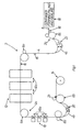
- FIG. 1 With initial reference to Fig. 1, there is shown an apparatus 2 according to the invention, and the reference numeral 18 indicates a packaging machine for forming package containers from a packaging sheet material web 4. It will be understood that the apparatus 2 may be either incorporated in the packaging machine or filling machine 18, or located upstream of such machine.
- Web 4 is fed through packaging machine 2 by means of an appropriate drive 6a-e in a feed direction 8.
- Drive 6a-e is adapted for intermittently feeding web 4 at an intermittent feed section 2a of machine 2, and for continuously feeding web 4 at a continuous infeed section 2b and a continuous outfeed section 2c, arranged respectively upstream and downstream of the intermittent feed section 2a with respect to web feed direction 8.
- a hole punching station 10 for punching holes in web 4
- an opening device moulding station 12 for injection moulding thermoplastics material opening devices at the holes provided on web 4.
- Drive 6a-e is adapted for intermittently feeding web 4 through hole punching station 10 such that web 4 is appropriately stopped and correctly positioned at hole punching station 10 for a time sufficient to punch the holes in web 4
- drive 6a-e is also adapted for intermittently feeding web 4 through opening device moulding station 10 such that the holes in web 4 are appropriately stopped and correctly positioned at opening device moulding station 10 for a time sufficient to mould opening devices at the holes punched previously at hole punching station 10.
- Drive 6a-e includes continuous feed rollers 6b and 6c arranged respectively at continuous infeed section 2b for unwinding and feeding web 4 from a reel 14 of packaging material web, and at continuous outfeed section 2c for continuously feeding web 4 with opening devices 16 moulded thereon to a container forming station 18 for forming and sealing containers from web 4 and filling the containers with product.
- Drive 6a-e further includes at intermittent feed section 2a intermittent feed rollers 6a, tensioning rollers 6d, and an idler roller 6e which together mutually cooperate so as to maintain the tension of web 4 at intermittent feed section 2a substantially constant in a stopped position, so that the hole punching and opening device moulding operations may be carried out with sufficient precision.
- the particular arrangement of drive 6a-e forms an infeed buffer magazine 20 and an outfeed buffer magazine 22.
- Infeed buffer magazine 20 includes a changing infeed web length 4b which extends between tensioning rollers 6d and continuous feed rollers 6b and which moves vertically along direction 20' such that infeed web length 4b changes in size (as indicated by dashed lines in Fig.1) to appropriately compensate for the interface between intermittent feed section 2a and continuous infeed section 2b.
- outfeed buffer magazine 22 includes a changing outfeed web length 4c which extends between intermittent drive rollers 6a and continuous feed rollers 6c and which moves vertically in direction 22' such that outfeed web length 4c changes in size (as indicated by dashed lines in Fig.1) to appropriately compensate for the interface between intermittent feed section 2a and continuous outfeed section 2c.
- the feeding of web 4 is continuous at roll 14 and container forming station 18 while the feeding of web 4 is intermittent at hole punching station 10 and opening device moulding station 12.
- Fig. 1 three hole punching stations 10 and three opening device moulding stations 12 are shown, such that three holes are formed in web 4 and three opening devices are moulded in web 4 for each intermittent stopped position of web 4.
- the particular number of hole punching stations 10 and opening device moulding stations 12 may vary according to the requirements.
- hole punching stations 10 and opening device moulding stations 12 may move relative to one another respectively in directions 10a and 12a along the extension of feeding of web 4, so that the holes and opening devices provided on web may be relatively spaced in different positions to allow to form packaging containers of different sizes.
- Apparatus and methods for feeding web 4, for punching holes in web 4, and for forming and sealing containers from web 4 and filling the containers 5 with product, in the manner as described above, are known, and for example are included in the TBA/19-System manufactured by Tetra Brik of Modena, Italy.
- Opening device moulding station 10 positioned in combination with packaging machine 2 advantageously provides an efficient and effective means for continuously moulding an opening device on a web fed from a roll and for successively forming, sealing, and filling a packaging container in the same compact line and continuous method.
- the adhesion of separately formed and supplied opening devices to the web, as is carried out in conventional apparatus, is eliminated, thereby to provide savings in time and cost related to the separate production, storage, and transport of the separately formed opening devices.
- opening device moulding station 10 may operate in many different manners, for example to mould opening devices on a fed web which is then rolled into a web reel for later use, or for example to mould opening devices on any type and shape of packaging sheet material such as packaging material blanks or protruding packaging material flaps to mention only a few.
- packaging machine 2 may be provided in an alternative form, such that web reel 14 is already provided with prestamped holes so as to allow to eliminate hole punch station 10, and/or such that the entire drive of web 4 is performed intermittently.
- container forming station 18 may be any one of a number of forming stations used to form and seal packages of different sizes and shapes and to fill different products into the formed packages.
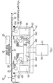
- Opening device moulding station 10' includes a first mould tool 20 and a second mould tool 22 which are arrangeable relative to web 4 in closed positions so as to be in contact respectively with a first side 24 of web 4 and a second side 26 of web 4 (Figs. 4 and 4a), when web 4 is in a stopped position at opening device moulding station 10'.
- First mould tool 20 and second mould tool 22 are also arrangeable relative to web 4 in open positions so as to be positioned distally respectively from first web side 24 and second web side 26 (Fig. 3), so as to allow the intermittent feeding of web 4 in feed direction 8.
- first mould tool 20 includes a single inner mould tool 20 which in operates in a fixed position
- second mould tool 22 includes a pair of half outer mould tools 22a and 22b which are driven between the open and closed positions relative to one another, and relative to web 4 and to inner mould tool 20, by a drive mechanism which is described hereinafter.
- Inner mould tool 20 is arranged for contact with web first side 24 destined to form an inner side of the packaging container formed with web 4, while outer mould tools 22a and 22b are arranged for contact with web second side 26 destined to form an outer side of the packaging container formed with web 4.
- a mould cavity 28 is formed between inner mould tool 20 and half outer mould tools 22a and 22b in which a hole edge 30, of a hole 32 in web 4 correctly positioned at opening device moulding station 10', is accommodated.
- Mould cavity 28 includes in the embodiment shown a portion 28a for forming a lid portion of the opening device 16, a portion 28b for forming a base portion of opening device 16 for connection to web 4, and a connecting portion 28c for forming a reduced thickness tearing edge of opening device 16 for aiding in releasing the lid portion from the base portion.
- the present disclosure relates more in particular to the manner in which opening device is moulded to web 4 at hole edge 30 thereof, while opening device 16 may assume any number of different overall shapes.
- hole edge 30 is circumferential to completely enclose the hole in web 4, and preferably the entire hole edge 30 is arranged inside base forming portion 28a of mould cavity 28 prior to injection, while base forming portion 28b is also circumferential and has a dimension sufficient to completely enclose hole edge 30.
- hole edge 30, base forming portion 28b, and connecting portion 28c are ovular ring-shaped in a longitudinal cross section extending substantially parallel to the extension of web 4, and lid forming portion 28a is ovular disc-shaped in a longitudinal cross section extending substantially parallel to the extension of web 4.
- a gap 34 is formed between upper and lower mould tools 20 and 22 which preferably has a width dimension smaller than the thickness of packaging web material 4 thereby to compress web 4 inside gap 34 and form a seal sufficient to prevent any significant leakage of the heated thermoplastics material outside of mould cavity 28.
- Opening device moulding station 10' further includes an injection passage 36 for injecting heated thermoplastics material into mould cavity 28.
- injection passage 36 for injecting heated thermoplastics material into mould cavity 28.
- injection passage 36 may be carried out using any conventional method and apparatus known and available to a skilled person in the art.
- Injection passage 36 extends in fixed inner mould tool 20 in the particular embodiment shown, and in accordance with a preferred aspect of the invention, injection passage 36 is configured such that thermoplastics material is injected directly into mould cavity 28 at an injection point 38 of mould cavity 28 which is located distally from hole edge 30.
- the heated thermoplastics material advantageously enters the mould cavity at a position which permits the filling of the mould cavity to be carried out in an effective and efficient manner.
- the heated plastics material will flow from injection point 38 smoothly and evenly initially distally from hole edge 30 and successively to fill base forming portion 28b of mould cavity 28 so that the heated plastics material makes contact with hole edge 30 at the end of the injection step. The times required for each injection step are minimised in order to increase the efficiency of the opening device moulding operation.
- Injection point 38 in the particular embodiment is arranged at lid forming portion 28a of mould cavity 28, in a substantially central position with respect to base forming portion 28b. Such an arrangement allows to fully maximise the efficiency of material flow from injection point 38 symmetrically and evenly initially distally from hole edge 30 and successively to fill base forming portion 28b of mould cavity 28.
- injection passage 36 extends in inner mould tool 20 in a direction which is substantially perpendicular to the extension of lid forming portion 28c of mould cavity 28 so as to fully avoid subjecting surfaces of web 4 to the flow of heated thermoplastics material.
- Inner mould tool 20 and half outer mould tools 22a and 22b are driven between the open and closed positions relative to one another, and relative to web 4 and to inner mould tool 20, by a drive mechanism 40.
- Drive mechanism 40 is coordinated with drive 6a-e for feeding web 4, with hole punching station, and with the injection of heated thermoplastics material through injection passage 36, so as to provide a continuous production of moulded opening devices 16 on web 4.
- Drive mechanism 40 includes a supporting structure 42 for supporting half outer mould tools 22a and 22b such that in the open position half outer mould tools 22a and 22b are mutually spaced from each other in an extension plane extending substantially parallel to the plane of extension of web 4 (Fig. 3) and such that in the closed position half outer mould tools 22a and 22b are mutually arranged in contact with each other and with second web side 26 (Figs. 4-4a).
- Drive mechanism 40 also includes a driver 44 for moving half outer mould tools 22a and 22b from the open position to the closed position and vice versa such that the direction of movement of each of half outer mould tools between the open and closed positions includes a directional component extending parallel to the extension plane of web 4 and a directional component extending perpendicularly to the extension plane of web 4.
- drive mechanism 40 which moves half outer mould tools 22a and 22b in such directions as they move between the open and closed positions advantageously allow to effectively form opening devices of many various shapes which may include in particular portions which protrude and extend in a plane which is parallel to the extension plane of web 4.
- drive mechanism 40 is such that outer half mould tools 22a and 22b mutually arrive and make contact together at the closed position with a delicate approach since the movement of each of outer half mould tools 22a and 22b may include a direction component parallel to the extension plane of web 4 which is minimised while still achieving mutual contact in the closed position.
- Such a delicate approach of outer half mould tools 22a and 22b advantageously provides for minimum wear of outer half mould tools 22a and 22b.
- drive mechanism 40 is configured such that the direction of movement of each of outer half mould tools 22a and 22b between the open and closed positions tangentially follows a circular path.
- the direction movement component parallel to the extension plane of web 4 of outer half mould tools 22a and 22b at the approach and release phases most near the closed position may be minimised virtually to zero while such direction movement component parallel to the extension plane of web 4 in phases away from the closed position may be rapidly increased, so as to minimise the space requirements of opening device moulding station 10' and so as to minimise wear on outer half mould tools 22a and 22b, while still maintaining flexibility with regard to forming opening devices of different shapes.
- Supporting structure 42 includes a fixed support frame having a horizontal base 46 and arm pairs 48a-c extending vertically upward from base 42.
- Supporting structure further includes lever pairs 50 and 52 freely pivoted respectively between lateral arm pairs 48a and 48c and outer half mould tools 22a and 22b about pivot axes which extend substantially parallel to the plane of extension of web 4.
- Supporting structure 42 further includes a horizontal slide plate 54 having slots 54a in which bolts 54b connected to each of outer half mould tools 22a and 22b are slidably accommodated. Slots 54a extend in slide plate 54 such that each of outer half mould tools 22a and 22b are slidably supported on slide plate 54 in a linear direction extending parallel to web feed direction 8.
- Driver 44 includes a fluid-actuated cylinder 55 having a stem slidably extending through fixed base 46 and connected to slide plate 54 for reciprocatingly moving slide plate 54 in a vertical direction extending perpendicularly to the extension of web 4.
- drive mechanism 40 causes outer half mould tools 22a and 22b to move between the open and closed positions along a circular path centred about the pivot axes respectively of lever pairs 50 and 52 and lateral arms 48a and 48c.
- outer half mould tools 22a and 22b, of lateral arms 48a and 48c, and of lever pairs 50 and 52 are such that when outer half mould tools 22a and 22b are arranged in contact in the closed position, a contact force between the mating surfaces of outer half mould tools 22a and 22b is created sufficient to provide an adequate seal of mould cavity 28 such that heated thermoplastics material will not leak excessively out of mould cavity 28 at the location of the mating surfaces of outer half moulds 22a and 22b.
- an adjustable biasing device for adjustably setting the contact force between outer half moulds 22a and 22b in the closed position.
- lateral arms 48a and 48c are provided with through gaps 56 which make lateral arms 48a and 48c relatively flexible in a direction parallel to web feed direction 8, and a pair of tension rods 58 are interconnected between lateral arms 48a and 48c.
- Tension rods 58 are freely slidably disposed in central arms 48b, and adjustment nuts 58a are adjustably screwed at the ends of tension rods 58.
- Fig. 4 illustrates the outward flexure of lateral arms 48a and 48c when outer half mould tools 22a and 22b are in the closed mating position, and adjustment of nuts 58a will properly select the desired contact force between half mould tools 22a and 22b in the closed position.
- the configuration of supporting structure 42 is such that in the closed position of outer half mould tools 22a and 22b (Fig. 4), the portion of web 4 which is in contact with outer half mould tools 22a and 22b extends in a plane which is distally spaced from the normal plane of extension of web 4 in the open position of outer half mould tools 22a and 22b (Fig. 3).
- web 4 in the spaced position from its normal extension is put under an added tension which advantageously facilitates the release of web 4 and moulded opening device 16 from mould tools 20 and 22 as such mould tools 20 and 22 move away from the closed position to the open position,
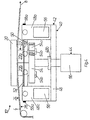
- Opening device moulding station 10 includes a first mould tool 20' and a second mould tool 22' which are arrangeable relative to web 4 in closed positions so as to be in contact respectively with a first side 24 of web 4 and a second side 26 of web 4 (Figs. 6 and 6a), when web 4 is in a stopped position at opening device moulding station 10".
- First mould tool 20' and second mould tool 22' are also arrangeable relative to web 4 in open positions so as to be positioned distally respectively from first web side 24 and second web side 26 (Fig. 5), so as to allow the intermittent feeding of web 4 in feed direction 8.
- First mould tool 20' includes a single inner mould tool 20' 5 movable in a vertical direction
- second mould tool 22' includes a pair of lateral outer mould tools 22a' and 22b' each movable in the vertical and a horizontal direction.
- Inner mould tool 20' and lateral outer mould tools 22a' and 22b' are driven between the open and closed positions relative to one another, and relative to web 4, by a drive mechanism which is described hereinafter.
- a mould cavity 28' is formed between inner mould tool 20' and lateral outer mould tools 22a and 22b in which hole edge 30 of hole 32 in web 4 correctly positioned at opening device moulding station 10" is accommodated.
- Mould cavity 28' includes a portion 28a' for forming a lid portion of the opening device 16, a portion 28b' for forming a base portion of opening device 16 for connection to web 4, and a connecting portion 28c' for forming a reduced thickness tearing edge of opening device 16 for aiding in releasing the lid portion from the base portion.
- the entire hole edge 30 is preferably arranged inside base forming portion 28a' prior to injection, while base forming portion 28b' is circumferential and has a dimension sufficient to completely enclose hole edge 30.
- base forming portion 28b' and connecting portion 28c' are ovular ring-shaped in a longitudinal cross section extending substantially parallel to the extension of web 4
- lid forming portion 28a' is ovular disc-shaped in a longitudinal cross section extending substantially parallel to the extension of web 4.
- a gap 34' is formed between upper and lower mould tools 20' and 22' which preferably has a width dimension smaller than the thickness of packaging web material 4 thereby to compress web 4 inside gap 34' and form a seal sufficient to prevent any significant leakage of the heated thermoplastics material outside of mould cavity 28'.
- Opening device moulding station 10" further includes an injection passage 36' for injecting heated thermoplastics material into mould cavity 28'.
- Injection passage 36' extends in a fixed injection head 60 which has an upper end portion 60a forming part of second mould tool 22', as seen in Fig. 6a. Accordingly lateral outer mould tools 22a' and 22b' are movably arrangeable with respect to fixed upper end portion 60a in the closed moulding position, forming mould cavity 28'.
- Injection passage 36' is configured such that thermoplastics material is injected directly into mould cavity 28' at an injection point 38' of mould cavity 28' which is located distally from hole edge 30, thereby to achieve the advantageous effects as obtained by the above described first embodiment of opening device moulding station 10'.
- Injection passage 36' moreover extends in outer mould tool 22' in a direction which is substantially perpendicular to the extension of lid forming portion 28c' of mould cavity 28', distally from surfaces of web 4.
- the drive mechanism for driving inner mould tool 20' and lateral outer mould tools 22a' and 22b' are between the open and closed positions includes a movable support frame 62 arranged circumferentially about fixed injection head 60 and movable in a vertical direction, and a fixed support frame 64 supporting fluid- activated cylinders 66a-b and 68 having stems 66a'-b' and 68' connected respectively to movable support frame 62 and inner mould tool 20' for reciprocatingly moving these elements in the vertical direction.
- the drive mechanism further includes fluid-activated cylinders 70a and 70b having stems 70a' and 70b' connected respectively to lateral outer mould tools 22a' and 22b' for reciprocatingly moving these elements in the horizontal direction.
- actuation of cylinders 66a-b, 68, and 70a-b is coordinated with drive 6a-e for feeding web 4, with hole punching station 10, and with the injection of heated thermoplastics material through injection passage 36', so as to provide a continuous production of moulded opening devices 16 on web 4.
Landscapes
- Engineering & Computer Science (AREA)
- Manufacturing & Machinery (AREA)
- Mechanical Engineering (AREA)
- Moulds For Moulding Plastics Or The Like (AREA)
- Injection Moulding Of Plastics Or The Like (AREA)
- Containers And Plastic Fillers For Packaging (AREA)
- Packages (AREA)
- Processing And Handling Of Plastics And Other Materials For Molding In General (AREA)
- Auxiliary Devices For And Details Of Packaging Control (AREA)
- Control And Other Processes For Unpacking Of Materials (AREA)
Abstract
Claims (7)
- Appareil de moulage d'un dispositif d'ouverture (2) pour des dispositifs d'ouverture en matériau de plastique de moulage par injection (16) au niveau de trous dans une bande de matériau de feuille d'emballage (4), comprenant :dans lequel dans les positions fermées desdits premier et second outils formant moules (20, 22), une cavité de moule (28) est formée entre lesdits premier et second outils formant moules (20, 22) pour adapter au moins partiellement une arête de trou (30) dans la bande (4) positionnée au niveau de ladite station de moulage d'un dispositif d'ouverture (12) ;une station de moulage d'un dispositif d'ouverture (12),au moins un premier outil formant moule (20) pouvant être agencé dans une position fermée de manière à être en contact avec un premier côté (24) de la bande (4) positionné au niveau de ladite station de moulage d'un dispositif d'ouverture (12) et pouvant être agencé dans une position ouverte de manière à être positionné de manière distale depuis le premier côté (24) de la bande (4) positionnée au niveau de ladite station de moulage d'un dispositif d'ouverture (12) ;au moins un second outil formant moule (22) pouvant être agencé dans une position fermée de manière à être en contact avec un second côté (26) de la bande (4) positionnée au niveau de ladite station de moulage d'un dispositif d'ouverture (12) et pouvant être agencé dans une position ouverte de manière à être positionné de manière distale depuis le second côté (26) de la bande (4) positionnée au niveau de ladite station de moulage d'un dispositif d'ouverture (12) ;
un passage d'injection (36) pour injecter un matériau thermoplastique dans ladite cavité de moule (28) dans laquelle ledit passage d'injection (36) s'étend dans au moins l'un desdits premier et second outils formant moules de sorte que le matériau thermoplastique est injecté directement dans la cavité de moule au niveau d'un point d'injection (38) de la cavité de moule (28) qui est située de manière distale depuis ladite arête de trou (30) adaptée dans ladite cavité de moule (28) ; et
un mécanisme d'entraínement (40) pour déplacer de manière sélective ledit premier outil formant moule (20) et ledit second outil formant moule (22) entre lesdites positions ouverte et fermée,
au moins l'un (22) desdits premier et second outils formant moules (20, 22) comprenant une paire d'outils formant demi-moules (22a, 22b),
caractérisé en ce que ledit mécanisme d'entraínement (40) comprend un pignon menant (44) pour déplacer lesdits outils formant demi-moules (22a, 22b) simultanément depuis la position ouverte vers la position fermée et vice-versa de sorte que le sens du mouvement de chacun desdits outils formant demi-moules (22a, 22b) entre lesdites positions ouverte et fermée comprend un composant directionnel parallèle à un plan d'extension de ladite bande (4) et un composant directionnel s'étendant perpendiculairement audit plan d'extension, lesdits sens de mouvement desdits outils formant demi-moules (22a, 22b) étant tangents l'un par rapport à l'autre à proximité de ladite position fermée. - Appareil selon la revendication 1, caractérisé en ce que ledit mécanisme d'entraínement (40) est configuré de sorte que lesdits outils formant demi-moules (22a, 22b) suivent un trajet circulaire entre lesdites positions ouverte et fermée.
- Appareil selon la revendication 1 où 2, caractérisé en ce que ledit mécanisme d'entraínement (40) comprend une structure de support (42) pour supporter lesdits outils formant demi-moules (22a, 22b) de sorte que dans la position ouverte lesdits outils formant demi-moules (22a, 22b) sont mutuellement espacés l'un de l'autre dans un plan d'extension s'étendant parallèlement au plan d'extension de la bande et de sorte que dans la position fermée lesdits outils formant demi-moules (22a, 22b) sont agencés mutuellement en contact l'un avec l'autre et avec ledit second côté de feuille (26).
- Appareil selon la revendication 3, caractérisé en ce que dans ladite position fermée ladite bande (4) s'étend dans un plan qui est espacé de manière distale du plan d'extension de ladite bande (4) dans ladite position ouverte.
- Appareil selon la revendication 3, caractérisé en ce qu'il comprend en outre un dispositif de polarisation ajustable (48a, 48c, 58, 58a) pour définir de manière ajustable une force de contact entre lesdits outils formant demi-moules (22a, 22b) dans ladite position fermée.
- Procédé de moulage par injection directe d'un dispositif d'ouverture de matériau plastique (16) dans un trou qui est disposé dans une bande (4) de matériau d'emballage et qui est doté d'une arête de trou (30), comprenant les étapes consistant à :déplacer au moins un premier outil formant moule (20) depuis une position ouverte vers une position fermée en contact avec un premier côté (24) de la bande de matériau de feuille d'emballage (4) et déplacer au moins un second outil formant moule (22) depuis une position ouverte vers une position fermée en contact avec un second côté (26) de la bande de matériau de feuille d'emballage (4), de ce fait formant une cavité de moule (28) définie entre lesdits premier et second outils formant moules (20, 22) d'une manière telle qu'au moins une partie de ladite arête de trou (30) est agencée à l'intérieur de ladite cavité de moule (28) ; etinjecter un matériau plastique dans ladite cavité de moule (28) de manière à former le dispositif d'ouverture de matériau plastique (16) dans lequel le matériau plastique est injecté directement dans la cavité du moule (28) au niveau d'un point d'injection (38) de la cavité de moule (28) qui est située de manière distale depuis ladite partie de l'arête de trou (30),ledit procédé comprenant l'étape consistant à fournir une paire d'outils formant demi-moules (22a, 22b) définissant au moins l'un desdits premier et second outils formant moules,et étant caractérisé par le fait qu'il comprend l'étape consistant à déplacer lesdits outils formant demi-moules (22a, 22b) pour définir un sens de mouvement de chacun desdits outils formant demi-moules (22a, 22b) entre lesdites positions ouverte et fermée, ayant un composant directionnel parallèle à un plan d'extension de ladite bande (4) et un composant directionnel s'étendant perpendiculairement audit plan d'extension, lesdits sens de mouvement desdits outils formant demi-moules (22a, 22b) étant tangents à proximité de ladite position fermée.
- Procédé selon la revendication 6, caractérisé en ce que le sens de mouvement de chacun desdits outils formant demi-moules (22a, 22b) entre lesdites positions ouverte et fermée suit un trajet circulaire.
Applications Claiming Priority (3)
| Application Number | Priority Date | Filing Date | Title |
|---|---|---|---|
| IT96MI002272A IT1286073B1 (it) | 1996-10-31 | 1996-10-31 | Apparecchiatura e procedimento per stampare un dispositivo di apertura su un foglio da imballaggio |
| ITMI962272 | 1996-10-31 | ||
| PCT/SE1997/001594 WO1998018608A1 (fr) | 1996-10-31 | 1997-09-23 | Appareil et procede destines a mouler un dispositif d'ouverture sur une feuille d'emballage |
Publications (2)
| Publication Number | Publication Date |
|---|---|
| EP0949992A1 EP0949992A1 (fr) | 1999-10-20 |
| EP0949992B1 true EP0949992B1 (fr) | 2002-11-20 |
Family
ID=11375135
Family Applications (1)
| Application Number | Title | Priority Date | Filing Date |
|---|---|---|---|
| EP97942364A Expired - Lifetime EP0949992B1 (fr) | 1996-10-31 | 1997-09-23 | Appareil et procede destines a mouler un dispositif d'ouverture sur une feuille d'emballage |
Country Status (22)
| Country | Link |
|---|---|
| US (2) | US6303066B1 (fr) |
| EP (1) | EP0949992B1 (fr) |
| JP (1) | JP3976347B2 (fr) |
| KR (1) | KR100364516B1 (fr) |
| CN (1) | CN1101305C (fr) |
| AR (1) | AR008519A1 (fr) |
| AT (1) | ATE228050T1 (fr) |
| AU (1) | AU720593B2 (fr) |
| BR (1) | BR9712608A (fr) |
| CA (1) | CA2270464C (fr) |
| DE (1) | DE69717309T2 (fr) |
| DK (1) | DK0949992T3 (fr) |
| ES (1) | ES2187818T3 (fr) |
| FI (1) | FI114301B (fr) |
| HU (1) | HU222425B1 (fr) |
| IT (1) | IT1286073B1 (fr) |
| NO (1) | NO316061B1 (fr) |
| PL (1) | PL184895B1 (fr) |
| RU (1) | RU2196046C2 (fr) |
| TR (1) | TR199900932T2 (fr) |
| UA (1) | UA54461C2 (fr) |
| WO (1) | WO1998018608A1 (fr) |
Cited By (2)
| Publication number | Priority date | Publication date | Assignee | Title |
|---|---|---|---|---|
| US8038924B2 (en) | 2003-09-19 | 2011-10-18 | Tetra Laval Holdings & Finance S.A. | Method of controllably conveying an object and an apparatus for conveying a web |
| US8641403B2 (en) | 2006-01-27 | 2014-02-04 | Tetra Laval Holdings & Finance S.A. | Unit and method for molding opening devices for application to packages of pourable food products |
Families Citing this family (31)
| Publication number | Priority date | Publication date | Assignee | Title |
|---|---|---|---|---|
| SE521876C2 (sv) * | 1999-12-22 | 2003-12-16 | Tetra Laval Holdings & Finance | Flerstegsenhet för bearbetning av ett banformat förpackningsmaterial i en maskin för förpackning av livsmedel |
| JP4566318B2 (ja) * | 2000-02-25 | 2010-10-20 | 臼井国際産業株式会社 | 軸流ファン |
| US6467238B1 (en) | 2000-06-15 | 2002-10-22 | Tetra Laval Holdings & Finance, Sa | Direct injection molded closure and method therefor |
| SE521912C2 (sv) | 2000-11-28 | 2003-12-16 | Tetra Laval Holdings & Finance | Förfarande för att anordna öppningsanordningar direkt på en förpackningsmaterialbana för hällbara produkter och en förpackning erhållen därigenom. |
| ES2292554T3 (es) * | 2001-02-16 | 2008-03-16 | TETRA LAVAL HOLDINGS & FINANCE SA | Metodo y unidad para esterilizar material en laminas de envasado para fabricar envases cerrados hermeticamente de productos alimenticios que se pueden verter. |
| ATE278609T1 (de) * | 2001-04-10 | 2004-10-15 | Tetra Laval Holdings & Finance | Einheit zum bearbeiten einer verpackungsmaterialbahn in einer verpackungsmaschine für nahrungsmittel und verfahren zum indexieren einer verpackungsmaterialbahn darin |
| SE523936C2 (sv) * | 2001-12-19 | 2004-06-01 | Tetra Laval Holdings & Finance | Formsprutningsverktyg samt sätt att formspruta |
| SE524502C2 (sv) * | 2002-11-29 | 2004-08-17 | Tetra Laval Holdings & Finance | Formsprutningsanordning samt förfarande för formsprutning |
| SE524250C2 (sv) * | 2002-11-29 | 2004-07-13 | Tetra Laval Holdings & Finance | Formsprutningsanordning samt förfarande för öppnande och slutande av en delbar form i en formsprutningsanordning |
| SE525597C2 (sv) * | 2002-12-06 | 2005-03-15 | Tetra Laval Holdings & Finance | Öppningsanordning förpackning samt sätt att förse en förpackning med en öppningsanordning |
| SE0203616D0 (sv) * | 2002-12-06 | 2002-12-06 | Tetra Laval Holdings & Finance | Öppningsanordning, förpackning samt sätt att förse en förpackning med en öppningsanordning |
| SE526408C2 (sv) * | 2004-01-13 | 2005-09-06 | Tetra Laval Holdings & Finance | Flerstegsenhet för bearbetning av en förpackningsmaterialbana |
| RU2337871C1 (ru) * | 2004-06-04 | 2008-11-10 | Нисса Принтинг Ко., Лтд. | Устройство для нанесения отделки внутри формы и устройство для подачи листа для отделки в горизонтальном направлении |
| US7313895B2 (en) * | 2004-07-20 | 2008-01-01 | Tetra Laval Holdings & Finance, Sa | Molding unit for forming direct injection molded closures |
| US7571846B2 (en) * | 2004-07-20 | 2009-08-11 | Tetra Laval Holdings & Finance, S.A. | Carton blank for direct injection molded closures |
| JP2008155954A (ja) * | 2006-12-24 | 2008-07-10 | Nihon Tetra Pak Kk | 注出口栓、包装容器及び包装容器の製造法 |
| ES2383205T3 (es) * | 2007-06-28 | 2012-06-19 | Tetra Laval Holdings & Finance S.A. | Método de dispositivos de apertura de moldeo por inyección en material de hoja para el empaquetado de productos alimenticios vertibles, y material de empaquetado y el paquete obtenido utilizando dicho método |
| MX2009011134A (es) * | 2007-09-28 | 2009-10-30 | Nissha Printing | Aparato para decoracion en molde y metodo para fabricar un producto moldeado decorado en molde. |
| JP5177846B2 (ja) * | 2007-11-24 | 2013-04-10 | 日本テトラパック株式会社 | 包装容器 |
| EP2357138B1 (fr) * | 2010-02-12 | 2012-10-17 | Tetra Laval Holdings & Finance S.A. | Dispositif et procédé pour alimenter une bande de matériau d'emballage |
| JP5619636B2 (ja) * | 2011-01-25 | 2014-11-05 | 小島プレス工業株式会社 | ダイレクト成形機 |
| JP5619643B2 (ja) | 2011-02-01 | 2014-11-05 | 小島プレス工業株式会社 | ダイレクト成形機 |
| DE102012106190A1 (de) * | 2012-07-10 | 2014-01-16 | Focke & Co. (Gmbh & Co. Kg) | Vorrichtung zur Herstellung von Zuschnitten insbesondere für Packungen für Zigaretten |
| JP2013035290A (ja) * | 2012-08-25 | 2013-02-21 | Nihon Tetra Pak Kk | 包装容器の製造法 |
| NO2848399T3 (fr) * | 2013-09-13 | 2018-02-10 | ||
| EP2889115B1 (fr) | 2013-12-31 | 2018-01-31 | Tetra Laval Holdings & Finance S.A. | Appareil pour former des dispositifs d'ouverture sur une feuille de matériau d'emballage pour produits alimentaires versables |
| ES2666572T3 (es) | 2013-12-31 | 2018-05-07 | Tetra Laval Holdings & Finance S.A. | Un aparato y un método formar dispositivos de apertura en un material de envasado de lámina para envasar productos alimenticios que se pueden verter |
| JP7224378B2 (ja) * | 2018-06-12 | 2023-02-17 | テトラ ラバル ホールディングス アンド ファイナンス エス エイ | 包装材料のシート上に開放機器を射出成形するように構成された成形装置 |
| JP7353045B2 (ja) * | 2019-03-11 | 2023-09-29 | 藤森工業株式会社 | 容器及びその製造方法 |
| CN110053303B (zh) * | 2019-05-27 | 2024-03-15 | 康美包(苏州)有限公司 | 包装盒耳翼防翘起的预压装置以及预压方法 |
| WO2021239608A1 (fr) * | 2020-05-27 | 2021-12-02 | Tetra Laval Holdings & Finance S.A. | Ensemble couvercle-bec verseur pour un emballage, procédé de fabrication d'un ensemble couvercle-bec verseur et emballage comportant un ensemble couvercle-bec verseur |
Family Cites Families (11)
| Publication number | Priority date | Publication date | Assignee | Title |
|---|---|---|---|---|
| GB659191A (en) | 1949-02-18 | 1951-10-17 | Metal Box Co Ltd | Improvements in or relating to metal containers |
| GB1023886A (en) * | 1963-09-25 | 1966-03-30 | Metal Containers Ltd | Method of and mould for forming a bushing in an opening in a sheet material wall,and sheet material wall produced by said method |
| SE370203B (fr) * | 1972-12-18 | 1974-10-07 | Cerbo Ab | |
| US4244491A (en) * | 1977-12-15 | 1981-01-13 | Tokan Kogyo Co., Ltd. | Container cover member having synthetic resin openable portion |
| US4678158A (en) * | 1985-11-21 | 1987-07-07 | Triangle Tool Corporation | Injection mold including mold sidewall locking bars |
| DE3606280A1 (de) | 1986-02-27 | 1987-09-03 | Altstaedter Verpack Vertrieb | Verschliessvorrichtung fuer eine spritzeinrichtung |
| SU1391917A1 (ru) * | 1986-06-06 | 1988-04-30 | Московское Научно-Производственное Объединение По Механизированному Строительному Инструменту И Отделочным Машинам | Способ изготовлени армированной металлом пластмассовой детали с отверстием и форма дл его осуществлени |
| GB2198385B (en) * | 1986-12-05 | 1990-02-07 | Metal Box Plc | Apparatus for injection moulding |
| EP0370142A1 (fr) * | 1988-11-22 | 1990-05-30 | Sankyo Engineering Co. Ltd. | Moule à noyau coulissant pour le moulage par injection |
| SE462743B (sv) | 1988-12-16 | 1990-08-27 | Profor Ab | Saett att foerbinda ett griporgan med ett ark eller banformigt foerpackningslaminat |
| CN1066037A (zh) * | 1991-04-22 | 1992-11-11 | 天龙化学工业株式会社 | 广口容器的盖装置 |
-
1996
- 1996-10-31 IT IT96MI002272A patent/IT1286073B1/it active IP Right Grant
-
1997
- 1997-09-23 DE DE69717309T patent/DE69717309T2/de not_active Expired - Lifetime
- 1997-09-23 ES ES97942364T patent/ES2187818T3/es not_active Expired - Lifetime
- 1997-09-23 CA CA002270464A patent/CA2270464C/fr not_active Expired - Fee Related
- 1997-09-23 WO PCT/SE1997/001594 patent/WO1998018608A1/fr not_active Ceased
- 1997-09-23 PL PL97333205A patent/PL184895B1/pl unknown
- 1997-09-23 BR BR9712608-0A patent/BR9712608A/pt not_active IP Right Cessation
- 1997-09-23 RU RU99111778/12A patent/RU2196046C2/ru not_active IP Right Cessation
- 1997-09-23 JP JP52034498A patent/JP3976347B2/ja not_active Expired - Lifetime
- 1997-09-23 US US09/269,507 patent/US6303066B1/en not_active Expired - Lifetime
- 1997-09-23 KR KR1019997003733A patent/KR100364516B1/ko not_active Expired - Fee Related
- 1997-09-23 HU HU9904349A patent/HU222425B1/hu not_active IP Right Cessation
- 1997-09-23 AU AU44078/97A patent/AU720593B2/en not_active Ceased
- 1997-09-23 AT AT97942364T patent/ATE228050T1/de active
- 1997-09-23 TR TR1999/00932T patent/TR199900932T2/xx unknown
- 1997-09-23 DK DK97942364T patent/DK0949992T3/da active
- 1997-09-23 CN CN97199295A patent/CN1101305C/zh not_active Expired - Lifetime
- 1997-09-23 EP EP97942364A patent/EP0949992B1/fr not_active Expired - Lifetime
- 1997-09-23 UA UA99042439A patent/UA54461C2/uk unknown
- 1997-10-31 AR ARP970105093A patent/AR008519A1/es active IP Right Grant
-
1999
- 1999-04-29 FI FI990978A patent/FI114301B/fi not_active IP Right Cessation
- 1999-04-30 NO NO19992117A patent/NO316061B1/no not_active IP Right Cessation
-
2001
- 2001-08-10 US US09/925,658 patent/US6835342B2/en not_active Expired - Lifetime
Cited By (2)
| Publication number | Priority date | Publication date | Assignee | Title |
|---|---|---|---|---|
| US8038924B2 (en) | 2003-09-19 | 2011-10-18 | Tetra Laval Holdings & Finance S.A. | Method of controllably conveying an object and an apparatus for conveying a web |
| US8641403B2 (en) | 2006-01-27 | 2014-02-04 | Tetra Laval Holdings & Finance S.A. | Unit and method for molding opening devices for application to packages of pourable food products |
Also Published As
Similar Documents
| Publication | Publication Date | Title |
|---|---|---|
| EP0949992B1 (fr) | Appareil et procede destines a mouler un dispositif d'ouverture sur une feuille d'emballage | |
| US4604850A (en) | Pack for fluid filling materials with reclosable opening device | |
| KR101920543B1 (ko) | 유동성 식품을 포장하기 위한 시트 포장 재료에 개봉 장치를 형성하기 위한 장치 | |
| US4564139A (en) | Packaging means for filling materials which are capable of flow, having a re-closable opening means | |
| US6251325B1 (en) | Method and mould tools for injection moulding a plastics material part in a packaging sheet material | |
| US11518076B2 (en) | Molding apparatus configured to injection mold an opening device on a sheet of packaging material | |
| US7313895B2 (en) | Molding unit for forming direct injection molded closures | |
| US7563093B2 (en) | Injection compression moulding apparatus | |
| EP2411201B1 (fr) | Appareil et procédé pour thermoformer des objets et objets ainsi obtenus | |
| CA1178410A (fr) | Contenant avec bec verseur refermable pour fluides | |
| HK1024665B (en) | Apparatus and method for moulding an opening device on a packaging sheet | |
| IE52726B1 (en) | Pack for fluid filling materials with reclosable opening device |
Legal Events
| Date | Code | Title | Description |
|---|---|---|---|
| PUAI | Public reference made under article 153(3) epc to a published international application that has entered the european phase |
Free format text: ORIGINAL CODE: 0009012 |
|
| 17P | Request for examination filed |
Effective date: 19990531 |
|
| AK | Designated contracting states |
Kind code of ref document: A1 Designated state(s): AT CH DE DK ES FR GB IT LI NL SE |
|
| 17Q | First examination report despatched |
Effective date: 20001023 |
|
| GRAG | Despatch of communication of intention to grant |
Free format text: ORIGINAL CODE: EPIDOS AGRA |
|
| GRAG | Despatch of communication of intention to grant |
Free format text: ORIGINAL CODE: EPIDOS AGRA |
|
| GRAH | Despatch of communication of intention to grant a patent |
Free format text: ORIGINAL CODE: EPIDOS IGRA |
|
| GRAH | Despatch of communication of intention to grant a patent |
Free format text: ORIGINAL CODE: EPIDOS IGRA |
|
| GRAA | (expected) grant |
Free format text: ORIGINAL CODE: 0009210 |
|
| AK | Designated contracting states |
Kind code of ref document: B1 Designated state(s): AT CH DE DK ES FR GB IT LI NL SE |
|
| REF | Corresponds to: |
Ref document number: 228050 Country of ref document: AT Date of ref document: 20021215 Kind code of ref document: T |
|
| REG | Reference to a national code |
Ref country code: GB Ref legal event code: FG4D |
|
| REG | Reference to a national code |
Ref country code: CH Ref legal event code: EP |
|
| REF | Corresponds to: |
Ref document number: 69717309 Country of ref document: DE Date of ref document: 20030102 |
|
| REG | Reference to a national code |
Ref country code: CH Ref legal event code: NV Representative=s name: A. BRAUN, BRAUN, HERITIER, ESCHMANN AG PATENTANWAE |
|
| REG | Reference to a national code |
Ref country code: DK Ref legal event code: T3 |
|
| ET | Fr: translation filed | ||
| REG | Reference to a national code |
Ref country code: ES Ref legal event code: FG2A Ref document number: 2187818 Country of ref document: ES Kind code of ref document: T3 |
|
| PLBE | No opposition filed within time limit |
Free format text: ORIGINAL CODE: 0009261 |
|
| STAA | Information on the status of an ep patent application or granted ep patent |
Free format text: STATUS: NO OPPOSITION FILED WITHIN TIME LIMIT |
|
| 26N | No opposition filed |
Effective date: 20030821 |
|
| REG | Reference to a national code |
Ref country code: CH Ref legal event code: PFA Owner name: TETRA LAVAL HOLDINGS & FINANCE SA Free format text: TETRA LAVAL HOLDINGS & FINANCE SA#AVENUE GENERAL-GUISAN 70, P.O. BOX 430#1009 PULLY (CH) -TRANSFER TO- TETRA LAVAL HOLDINGS & FINANCE SA#AVENUE GENERAL-GUISAN 70, P.O. BOX 430#1009 PULLY (CH) |
|
| REG | Reference to a national code |
Ref country code: CH Ref legal event code: PCAR Free format text: NEW ADDRESS: HOLBEINSTRASSE 36-38, 4051 BASEL (CH) |
|
| PGFP | Annual fee paid to national office [announced via postgrant information from national office to epo] |
Ref country code: DK Payment date: 20140910 Year of fee payment: 18 |
|
| PGFP | Annual fee paid to national office [announced via postgrant information from national office to epo] |
Ref country code: GB Payment date: 20140917 Year of fee payment: 18 Ref country code: AT Payment date: 20140827 Year of fee payment: 18 |
|
| PGFP | Annual fee paid to national office [announced via postgrant information from national office to epo] |
Ref country code: ES Payment date: 20150810 Year of fee payment: 19 Ref country code: CH Payment date: 20150911 Year of fee payment: 19 |
|
| PGFP | Annual fee paid to national office [announced via postgrant information from national office to epo] |
Ref country code: SE Payment date: 20150911 Year of fee payment: 19 |
|
| PGFP | Annual fee paid to national office [announced via postgrant information from national office to epo] |
Ref country code: NL Payment date: 20150909 Year of fee payment: 19 |
|
| REG | Reference to a national code |
Ref country code: DK Ref legal event code: EBP Effective date: 20150930 |
|
| REG | Reference to a national code |
Ref country code: AT Ref legal event code: MM01 Ref document number: 228050 Country of ref document: AT Kind code of ref document: T Effective date: 20150923 |
|
| GBPC | Gb: european patent ceased through non-payment of renewal fee |
Effective date: 20150923 |
|
| PG25 | Lapsed in a contracting state [announced via postgrant information from national office to epo] |
Ref country code: GB Free format text: LAPSE BECAUSE OF NON-PAYMENT OF DUE FEES Effective date: 20150923 |
|
| REG | Reference to a national code |
Ref country code: FR Ref legal event code: PLFP Year of fee payment: 20 |
|
| PG25 | Lapsed in a contracting state [announced via postgrant information from national office to epo] |
Ref country code: AT Free format text: LAPSE BECAUSE OF NON-PAYMENT OF DUE FEES Effective date: 20150923 |
|
| PG25 | Lapsed in a contracting state [announced via postgrant information from national office to epo] |
Ref country code: DK Free format text: LAPSE BECAUSE OF NON-PAYMENT OF DUE FEES Effective date: 20150930 |
|
| PGFP | Annual fee paid to national office [announced via postgrant information from national office to epo] |
Ref country code: IT Payment date: 20160921 Year of fee payment: 20 Ref country code: DE Payment date: 20160920 Year of fee payment: 20 |
|
| PGFP | Annual fee paid to national office [announced via postgrant information from national office to epo] |
Ref country code: FR Payment date: 20160816 Year of fee payment: 20 |
|
| PG25 | Lapsed in a contracting state [announced via postgrant information from national office to epo] |
Ref country code: SE Free format text: LAPSE BECAUSE OF NON-PAYMENT OF DUE FEES Effective date: 20160924 |
|
| REG | Reference to a national code |
Ref country code: CH Ref legal event code: PL |
|
| REG | Reference to a national code |
Ref country code: SE Ref legal event code: EUG |
|
| REG | Reference to a national code |
Ref country code: NL Ref legal event code: MM Effective date: 20161001 |
|
| PG25 | Lapsed in a contracting state [announced via postgrant information from national office to epo] |
Ref country code: NL Free format text: LAPSE BECAUSE OF NON-PAYMENT OF DUE FEES Effective date: 20161001 |
|
| PG25 | Lapsed in a contracting state [announced via postgrant information from national office to epo] |
Ref country code: LI Free format text: LAPSE BECAUSE OF NON-PAYMENT OF DUE FEES Effective date: 20160930 Ref country code: CH Free format text: LAPSE BECAUSE OF NON-PAYMENT OF DUE FEES Effective date: 20160930 |
|
| REG | Reference to a national code |
Ref country code: DE Ref legal event code: R071 Ref document number: 69717309 Country of ref document: DE |
|
| REG | Reference to a national code |
Ref country code: ES Ref legal event code: FD2A Effective date: 20180507 |
|
| PG25 | Lapsed in a contracting state [announced via postgrant information from national office to epo] |
Ref country code: ES Free format text: LAPSE BECAUSE OF NON-PAYMENT OF DUE FEES Effective date: 20160924 |