EP0950272B1 - Modulare sonde - Google Patents
Modulare sonde Download PDFInfo
- Publication number
- EP0950272B1 EP0950272B1 EP98902414A EP98902414A EP0950272B1 EP 0950272 B1 EP0950272 B1 EP 0950272B1 EP 98902414 A EP98902414 A EP 98902414A EP 98902414 A EP98902414 A EP 98902414A EP 0950272 B1 EP0950272 B1 EP 0950272B1
- Authority
- EP
- European Patent Office
- Prior art keywords
- probe
- seal
- connector
- seal body
- connector body
- Prior art date
- Legal status (The legal status is an assumption and is not a legal conclusion. Google has not performed a legal analysis and makes no representation as to the accuracy of the status listed.)
- Expired - Lifetime
Links
- 239000000523 sample Substances 0.000 title claims description 107
- 238000004880 explosion Methods 0.000 claims description 26
- 230000008878 coupling Effects 0.000 claims description 11
- 238000010168 coupling process Methods 0.000 claims description 11
- 238000005859 coupling reaction Methods 0.000 claims description 11
- 230000007613 environmental effect Effects 0.000 claims description 9
- 230000004888 barrier function Effects 0.000 claims description 7
- 238000007789 sealing Methods 0.000 claims description 3
- 230000013011 mating Effects 0.000 claims 2
- 238000006243 chemical reaction Methods 0.000 claims 1
- 239000000463 material Substances 0.000 description 15
- 238000004382 potting Methods 0.000 description 13
- 238000009434 installation Methods 0.000 description 9
- 239000004809 Teflon Substances 0.000 description 7
- 229920006362 Teflon® Polymers 0.000 description 7
- 239000007788 liquid Substances 0.000 description 3
- 238000000034 method Methods 0.000 description 3
- 239000012530 fluid Substances 0.000 description 2
- 238000004519 manufacturing process Methods 0.000 description 2
- 210000002445 nipple Anatomy 0.000 description 2
- 230000008569 process Effects 0.000 description 2
- 238000004886 process control Methods 0.000 description 2
- 230000000712 assembly Effects 0.000 description 1
- 238000000429 assembly Methods 0.000 description 1
- 230000008901 benefit Effects 0.000 description 1
- 238000007664 blowing Methods 0.000 description 1
- 150000001875 compounds Chemical class 0.000 description 1
- 230000001143 conditioned effect Effects 0.000 description 1
- 239000004020 conductor Substances 0.000 description 1
- 231100001261 hazardous Toxicity 0.000 description 1
- 239000011810 insulating material Substances 0.000 description 1
- 229920001343 polytetrafluoroethylene Polymers 0.000 description 1
- 230000000717 retained effect Effects 0.000 description 1
- 238000003860 storage Methods 0.000 description 1
- -1 that is Substances 0.000 description 1
Images


Classifications
-
- H—ELECTRICITY
- H01—ELECTRIC ELEMENTS
- H01R—ELECTRICALLY-CONDUCTIVE CONNECTIONS; STRUCTURAL ASSOCIATIONS OF A PLURALITY OF MUTUALLY-INSULATED ELECTRICAL CONNECTING ELEMENTS; COUPLING DEVICES; CURRENT COLLECTORS
- H01R13/00—Details of coupling devices of the kinds covered by groups H01R12/70 or H01R24/00 - H01R33/00
- H01R13/46—Bases; Cases
- H01R13/52—Dustproof, splashproof, drip-proof, waterproof, or flameproof cases
- H01R13/527—Flameproof cases
-
- G—PHYSICS
- G01—MEASURING; TESTING
- G01F—MEASURING VOLUME, VOLUME FLOW, MASS FLOW OR LIQUID LEVEL; METERING BY VOLUME
- G01F23/00—Indicating or measuring liquid level or level of fluent solid material, e.g. indicating in terms of volume or indicating by means of an alarm
- G01F23/22—Indicating or measuring liquid level or level of fluent solid material, e.g. indicating in terms of volume or indicating by means of an alarm by measuring physical variables, other than linear dimensions, pressure or weight, dependent on the level to be measured, e.g. by difference of heat transfer of steam or water
- G01F23/26—Indicating or measuring liquid level or level of fluent solid material, e.g. indicating in terms of volume or indicating by means of an alarm by measuring physical variables, other than linear dimensions, pressure or weight, dependent on the level to be measured, e.g. by difference of heat transfer of steam or water by measuring variations of capacity or inductance of capacitors or inductors arising from the presence of liquid or fluent solid material in the electric or electromagnetic fields
- G01F23/263—Indicating or measuring liquid level or level of fluent solid material, e.g. indicating in terms of volume or indicating by means of an alarm by measuring physical variables, other than linear dimensions, pressure or weight, dependent on the level to be measured, e.g. by difference of heat transfer of steam or water by measuring variations of capacity or inductance of capacitors or inductors arising from the presence of liquid or fluent solid material in the electric or electromagnetic fields by measuring variations in capacitance of capacitors
- G01F23/268—Indicating or measuring liquid level or level of fluent solid material, e.g. indicating in terms of volume or indicating by means of an alarm by measuring physical variables, other than linear dimensions, pressure or weight, dependent on the level to be measured, e.g. by difference of heat transfer of steam or water by measuring variations of capacity or inductance of capacitors or inductors arising from the presence of liquid or fluent solid material in the electric or electromagnetic fields by measuring variations in capacitance of capacitors mounting arrangements of probes
-
- G—PHYSICS
- G01—MEASURING; TESTING
- G01F—MEASURING VOLUME, VOLUME FLOW, MASS FLOW OR LIQUID LEVEL; METERING BY VOLUME
- G01F23/00—Indicating or measuring liquid level or level of fluent solid material, e.g. indicating in terms of volume or indicating by means of an alarm
- G01F23/22—Indicating or measuring liquid level or level of fluent solid material, e.g. indicating in terms of volume or indicating by means of an alarm by measuring physical variables, other than linear dimensions, pressure or weight, dependent on the level to be measured, e.g. by difference of heat transfer of steam or water
- G01F23/28—Indicating or measuring liquid level or level of fluent solid material, e.g. indicating in terms of volume or indicating by means of an alarm by measuring physical variables, other than linear dimensions, pressure or weight, dependent on the level to be measured, e.g. by difference of heat transfer of steam or water by measuring the variations of parameters of electromagnetic or acoustic waves applied directly to the liquid or fluent solid material
- G01F23/284—Electromagnetic waves
-
- H—ELECTRICITY
- H01—ELECTRIC ELEMENTS
- H01R—ELECTRICALLY-CONDUCTIVE CONNECTIONS; STRUCTURAL ASSOCIATIONS OF A PLURALITY OF MUTUALLY-INSULATED ELECTRICAL CONNECTING ELEMENTS; COUPLING DEVICES; CURRENT COLLECTORS
- H01R13/00—Details of coupling devices of the kinds covered by groups H01R12/70 or H01R24/00 - H01R33/00
- H01R13/46—Bases; Cases
- H01R13/52—Dustproof, splashproof, drip-proof, waterproof, or flameproof cases
- H01R13/5219—Sealing means between coupling parts, e.g. interfacial seal
- H01R13/5221—Sealing means between coupling parts, e.g. interfacial seal having cable sealing means
-
- H—ELECTRICITY
- H01—ELECTRIC ELEMENTS
- H01R—ELECTRICALLY-CONDUCTIVE CONNECTIONS; STRUCTURAL ASSOCIATIONS OF A PLURALITY OF MUTUALLY-INSULATED ELECTRICAL CONNECTING ELEMENTS; COUPLING DEVICES; CURRENT COLLECTORS
- H01R13/00—Details of coupling devices of the kinds covered by groups H01R12/70 or H01R24/00 - H01R33/00
- H01R13/62—Means for facilitating engagement or disengagement of coupling parts or for holding them in engagement
- H01R13/622—Screw-ring or screw-casing
Definitions
- the present invention relates to a modular probe and transmitter assembly having an explosion proof barrier between the probe and the interior of the transmitter housing.
- Explosion proof transmitter housings and explosion proof enclosures for other process control equipment are known, but only having explosion proof housings does not complete the explosion proof installation when a probe forms part of the assembly. Both the housing or enclosure and the probe assembly itself must be approved for use in hazardous location installations. Direct mounted probes, that is, probes mounted directly to a housing, require a seal between the probe and the interior of the housing that is adequate to comply with the design requirements. In order to comply with the National Electric Code in the United States, an explosion proof barrier has to be located adjacent the housing and such a barrier also has to be provided for the probe.
- the present invention relates to a modular design of a probe and transmitter circuit housing where the probe is mounted directly to the housing and is used for sensing a parameter, such as sensing the level of a fluid or liquid in a tank.
- a probe and transmitter housing assembly of the present invention are used in an industrial process where the level of some component in the process has to be monitored.
- the probe may be a capacitance probe, a micro impulse radar probe, or another type of sensor probe.
- a probe connector includes an explosion proof potting compound barrier in a passageway of a connector body.
- the probe has a self contained pressure seal in a seal assembly that couples to the connector.
- the probe may be installed in a location such as the tank wall, prior to transmitter installation.
- the transmitter, with the explosion proof barrier connector is joined to the probe by threading or by other suitable connections known by people skilled in the art of connecting assemblies.
- the seal body and probe assembly can be left in place in the tank and the transmitter section may be removed or replaced from the connector without disassembly of the transmitter housing.
- the probe can remain installed and undisturbed while the transmitter is replaced.
- the transmitter housing thus can be separated from the probe and checked with independent measuring devices without exposing sensitive electronics to the environment of the installation or removing the probe from its installation.
- the probe can also be serviced while installed. This can be done by removing the connector body from the probe and servicing the probe from the exterior of the tank.
- An environmental seal which is an O-ring is used between the connector body and the seal body and it can be replaced without removing the transmitter housing from its connection to the explosion proof joint in the connector body.
- the probe can be fabricated separately from the connector body having the explosion proof joint, and separately from the transmitter housing, allowing for modular manufacturing of the probe.
- a factory sealed assembly designation can be used with the transmitter housing, connector body and probe assembly, which then can be sold as a unit.
- probes can be used.
- a micro impulse radar probe and a capacitive probe are shown herein.
- Other types of probes for different applications can be used as desired.
- the components are easily manufactured, and provide an intrinsically safe system with an explosion proof coupling for use between a probe and a companion transmitter circuit housing.
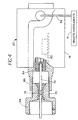
- a storage tank 10 used in a process control environment contains a liquid 12, the level of which is to be determined or measured.
- a tank port has a collar 14 on which a flange 16 is mounted.
- a modular probe assembly made according to the present invention indicated generally at 18 is supported on the flange.
- the probe assembly 18 is connected to a transmitter housing 20 which is a standard transmitter including a circuit that receives signals from a probe (or antenna) 22, and causes the signals to be conditioned and sent to a remote location.
- the transmitter housing 20 is connected to the probe 22 on the interior of the tank 10 through a modular coupling 24 made according to the present invention, which is part of the probe assembly 18.
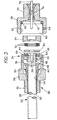
- the probe 22 as shown in Figures 2 and 3 as a capacitance probe, in the first form of the invention.
- the probe 22 forms one plate of a capacitance sensor.
- the second capacitive plate can be the tank wall or a reference probe.
- the probe 22, as shown is an elongated rod 25 covered with a sheath 26 of suitable material, such as Teflon (polytetrafluroethylene), which is an insulating material which makes the probe 22 usable with a conductive material.
- Teflon polytetrafluroethylene
- probes can be used such as the micro impulse radar probe or antenna, utilizing the same modular coupling 24.
- a Teflon sheath may be used to make the probe immune to corrosive materials.
- the probe 22 with the insulating sleeve 26 in place, is slid through a chamber 30 in a seal body 28 forming part of modular coupler 24 through a close fitting bore, from a larger open end.
- An integral threaded neck portion 32 surround the bores for the probe and extends along the probe 22.
- the neck portion 32 threads into tank flange 16.
- a pipe nipple will work or the seal body can be welded into the flange.
- interior chamber 30 of the seal body 28 has a tapered interior surface 34 at the end adjacent neck 32.
- the base end 36 of the sheath 26 is formed to that flared or tapered configuration.
- a ferrule 38 is slid over the probe 22 and fits within chamber 30.
- the ferrule 38 has a conical outer surface 40 that fits into the interior of tapered portion 36 of the insulating sheath 26.
- a lock ring 43 is slipped over the outer end of the rod 25 and fits within interior chamber 30.
- the lock ring 43 is fixed on the probe by set screws 44, at the outer end of the probe rod 25.
- An O-ring 46 is positioned between the ferrule 38 and the inner end of lock ring 43 and fits into a recess 48 in the end of lock ring 43.
- the individual parts can be seen more clearly in Figure 3.
- the probe 22 is slid into position in the seal body 28 and a nonconducting washer 50 is placed against the outer end of lock ring 43, and the probe 22, ferrule 38, lock ring 43 and washer 50 are slid as a unit into the chamber 30, with the probe extending out through the bore in neck 32.
- the washer 50 is backed with a number of Belville type spring washers 52 and a plug 54 is then threaded into threads 42 on the interior of chamber 30 to force the probe 22 and ferrule 38 into the seal body 28 and securely mount it.
- a seal is formed around the probe 22 with the insulating sleeve 26, the ferrule 38 and the O-ring 46 which provides a gas tight seal around the probe core or rod 25.
- the Belville washers provide a constant force on the seal 46, washer 50, lock ring 43 and ferrule 38 to maintain the seal under operating conditions.
- the plug 54 is adjusted for preloading the seal surfaces through the Belville washers.
- the plug 54, ferrule 38 and the probe can be removed so the probe assembly may be serviced or checked at a later time without disturbing the installation of the seal body 28 on tank flange 16.
- the rod 25 of the probe 22 has an electrical connector portion comprising a connector pin socket 56 formed in the end thereof in the seal body 28, and the washer 50, the Belville springs 52 and the plug 54 all have openings that will permit a connector pin to pass therethrough for connection to the socket.
- a threaded explosion barrier connector body 58 for the modular probe assembly 18 has an interior chamber 60 that is threaded as at 62 to receive the external threads 64 on the seal body 28, to make the assembly shown in Figure 2.
- An environmental seal O-ring 66 is provided in the inner end of the chamber 60.
- the O-ring surrounds a central passageway 67 in a threaded neck 70 of the connector body 58.
- the seal body 28 is threaded so that the outer end edge 68 seats on the O-ring 66, and it will provide an adequate environmental seal by tightening it one-quarter to three-quarters of a turn beyond hand tight. This provides protection for the socket to pin connector interface on the probe, at socket 56, from the outside environment.
- the environmental joint formed between end 68 and O-ring 66 also acts as a vent system for the factory seal designation. This joint can be locked in place with a suitable set screw 69 passing through the wall of the connector body 58.
- the threaded opening and set screw 69 and the threads 64 on seal body 28 form a vent to atmosphere.
- the explosion proof seal is a potting material filling 74 in bore 67 in the neck portion 70 of the threaded connector 58. As shown, the central passageway 67 is filled with a potting material 74 that has a sufficient length along the axis of passageway 67 to meet explosion proof requirements.
- the potting material also mounts an electrical connector portion comprising a connector pin 76 in place. Material 74 forms a potted joint which is never changed, and can be manufactured to conform to all of the requirements of the explosion proof rating.
- the bore 67 and the pin 76 are both irregularly shaped in cross section to reduce the likelihood of blowing out the pin or potting material.
- the connector pin 76 is of size to fit into the socket 56 and form an electrical connection between the probe rod 25 and electronics in the transmitter 20.
- the transmitter 20 includes a housing 78 with electronics indicated generally at 80 maintained therein for receiving signals from the probe 22 and then transmitting the signals to a remote instrument 81 along cabling 82.
- the electronic circuitry 80 is connected to the probe through the pin 76 shown in Figure 4.
- the pin 76 is received in a socket 84 mounted in the transmitter housing.
- the transmitter housing has a nipple 86 that is internally threaded, and it receives the end portions 70 of the threaded connector 58.
- the pin 76 is made of sufficient length so that it fits into the socket 84 and provides a good electrical connection.
- the explosion proof coupling thus is the threaded connector 58.
- the potting material 74 provides explosion proofing of the internal circuitry of the transmitter housing relative to the probe 22, which is mounted on connector body 58 and inserts into the process liquid or fluid.
- the transmitter housing 78 can be unthreaded or unscrewed from the connector body 58. and removed for service of the electronic components or other components that are to be worked on without altering the explosion proof potting material 74.
- the transmitter housing 78 is made explosion proof, as is commonly done.
- the connector body 58 can be left in place on the transmitter housing 78 and the threaded connector body 58 removed from the seal body 28, while the seal body is left in place on the probe 22.
- the threaded connector body 58 can be completely removed from the seal body 28, without disturbing the O-ring 46 or the seal created by the ferrule 38 and the Teflon sheath sealing portion 36.
- Teflon sheath sealing portion 36 can be adjusted after a certain length of time by retightening the plug 54 after the initial assembly.
- the probe 22 can be installed into the tank on the flange 16 by threading in the seal body 28.
- the threaded connector body 58 (with the explosion proof potting material seal) can be placed onto the transmitter housing 20 and then the transmitter housing threaded in place on the connector body.
- the entire unit (probe 22, seal body 28, connector body 58 and transmitter housing 20) can be assembled together for sale from the factory, and for installation if desired. Additionally, the transmitter housing 20 can be removed from the threaded connector body 58 while the threaded connector body 58 is retained on the seal body 28, without disturbing the seal provided by the O-ring 66, and thus protecting the internal connections of the pin 76 in the socket 56.
- the probe assembly 18 will be shipped separately from the transmitter, but they will be in a matched set so that they are compatible.
- a micro impulse radar antenna or probe also may be mounted in an assembly that provides explosion proof features.
- Such a probe is shown schematically in Figure 5.
- the micro impulse probe or antenna 90 can be held in a seal body 91.
- the seal body is threaded into or otherwise is fastened on a tank flange or other connector.
- a guide sleeve 91A serves to center a connector rod 91B and bears against a tapered Teflon seal 92 when a threaded plug 93 is threaded into the seal body, to compress the seal 92.
- the threaded plug 93 bears against a resilient washer 93A to load the sleeve 91A and Teflon seal 92 under a spring force.
- the Teflon seal 92 seats on a tapered interior surface 92A of the seal body 91.
- the potting material forming an explosion proof joint or seal is shown at 97 and fills a passageway in a connector body 98.
- a pin 99 is potted in the potting material 97.
- the pin 99 couples to connector rod 91B and carries signals between the antenna or probe 90 and circuitry in a transmitter housing mounted on the connector body 98.
- the connector body 98 is threaded with threads 101 on the end of the seal body 91, as in the first form of the invention.
- An environmental O-ring seal 100 is placed between the end of the seal body 91 and the inner end of a chamber in the connector body 98.
- the threads 101 between the end of the seal body 91 and connector body 98 provide a vent when pressure on the interior of the seal body causes the O-ring 100 to release its seal.
- the intermediate connector body 98 permits removal of the transmitter or the seal body independently, to provide the features set out in the first form of the invention.
- probe means an elongated sensor element having a portion held in a support body with a portion of the element protruding from the support body, whether the sensor element functions as an antenna or some other probe like member.
- a flat plate sensor inside a container, pipe, bin or tank can be supported by the seal body.
- the length of the potting material and the type of potting material used is selected according to known procedures and can be calculated to be greater than minimum lengths and minimum pressure ratings to meet explosion proof requirements.
Landscapes
- Physics & Mathematics (AREA)
- Electromagnetism (AREA)
- Engineering & Computer Science (AREA)
- Power Engineering (AREA)
- Thermal Sciences (AREA)
- Fluid Mechanics (AREA)
- General Physics & Mathematics (AREA)
- Measuring Fluid Pressure (AREA)
- Arrangements For Transmission Of Measured Signals (AREA)
Claims (11)
- Modulare Sondenanordnung (18) mit einem Dichtungskörper (28, 91), einer Sonde (22, 90) zum Führen elektrischer Signale, die im Dichtungskörper (28, 91) angeordnet und relativ zu einem Innenhohlraum des Dichtungskörpers (28, 91) abgedichtet ist,
einem Verbinderkörper (58, 98), der mit dem Dichtungskörper (28, 91) entfernbar und abdichtbar verbindbar ist und einen durchgehenden Innendurchgang (67) hat, einem elektrischen Verbinder (76, 99), der im Innendurchgang (67) mit einer explosionssicheren Sperre (74, 97) im Durchgang (67) befestigt ist, wobei der elektrische Verbinder (76, 99) mit der Sonde (22, 90) zum Führen der elektrischen Signale verbunden ist, wobei der Verbinderkörper (58, 98) einen Kopplungsabschnitt (70, 98) zum Koppeln des Verbinderkörpers (58, 98) mit einem Transmittergehäuse (20) hat. - Sondenanordnung nach Anspruch 1, wobei der Dichtungskörper (28, 91) und der Verbinderkörper (58, 98) miteinander entfernbar gekoppelt sind, um ein Entfernen des Verbinderkörpers (58, 98) vom Dichtungskörper (28, 91) zu ermöglichen.
- Sondenanordnung nach Anspruch 1 oder 2, wobei der Verbinderkörper (58, 98) einen gewindeten Endabschnitt zum Koppeln mit einem Transmittergehäuse aufweist.
- Sondenanordnung nach Anspruch 2, wobei der Verbinderkörper (58, 98) und der Dichtungskörper (28, 91) durch Gegengewindeabschnitte (62, 101) und eine Umgebungsdichtung (66, 100) zwischen den Gegengewindeabschnitten zum Abdichten des Dichtungskörpers (28, 91) relativ zum Verbinderkörper (58, 98) koppelbar sind.
- Sondenanordnung nach Anspruch 4, wobei der Verbinderkörper (58, 98) eine Innenkammer (60, 98) hat, die sich über einen Abschnitt des Dichtungskörpers (28, 91) aufschraubbar montiert ist, wobei die Umgebungsdichtung (66, 100) an das Ende des Dichtungskörpers (28, 91) und ein Stirnende der Kammer im Verbinderkörper (58, 98) anstößt, wenn sich der Verbinderkörper (58, 98) an Ort und Stelle auf dem Dichtungskörper (28, 91) befindet.
- Sondenanordnung nach einem der Ansprüche 1, 4 oder 5, wobei der Dichtungskörper (28, 91) folgendes aufweist: eine Kammer (20, 92A), die einen Endabschnitt der Sonde (22, 90) aufnimmt, wobei ein Abschnitt der Sonde (22, 90) aus einer Öffnung im Dichtungskörper (28, 91) in eine erste Richtung vorsteht, ein Federteil (52, 93A) in der Kammer zum Drücken des Endabschnitts der Sonde (22, 90) in die erste Richtung, um eine Dichtung (36, 38, 92) zwischen der Sonde (22, 90) und dem Dichtungskörper (28, 91) zu ergreifen, und einen Reaktionsstopfen (54, 93), der in der Kammer zum Drücken des Federteils in die erste Richtung angeordnet ist, um eine Federkraft auf die Dichtung (36, 38, 92) zwischen der Sonde (22, 90) und dem Dichtungskörper (28, 91) aufrechtzuerhalten.
- Sondenanordnung nach Anspruch 6, wobei die Dichtung (36, 38, 92) zwischen der Sonde (22, 90) und dem Dichtungskörper (28, 91) eine Dichtung mit kegeliger Oberfläche aufweist, die eine Außenfläche der. Sonde (22, 90) und eine kegelige Innenfläche (34, 92A) des Dichtungskörpers (28, 91) ergreift.
- Modulare Sondenanordnung nach Anspruch 4 oder 5, wobei die Umgebungsdichtung (66, 100) einen elastischen Ring aufweist, der sowohl am Verbinderkörper (58, 98) als auch am Dichtungskörper (28, 91) anliegt.
- Modulare Sonde nach einem der Ansprüche 1 bis 8, wobei der elektrische Verbinder (76, 99) einen ersten Endabschnitt, der mit der Sonde (22, 90) elektrisch verbunden ist, und einen zweiten Endabschnitt hat, der sich zur Verbindung mit elektronischen Komponenten in einem Gehäuse erstreckt, das durch den Kopplungsabschnitt (70) des Verbinderkörpers (58, 98) getragen wird.
- Modulare Sonde nach einem der Ansprüche 1 bis 8, wobei der elektrische Verbinder im Durchgang des Verbinderkörpers (58, 98) einen Stift (76, 99) aufweist, wobei die Sonde (22, 90) eine Buchse zum Aufnehmen eines ersten Endabschnitts des Stifts (76, 99) hat und sich ein zweites Ende des Stifts aus dem Verbinderkörper zum Koppeln zum Erweitern elektrischer Schaltungen nach außen erstreckt.
- Modulare Sonde nach Anspruch 4, wobei der Dichtungskörper (28, 91) mit dem Verbinderkörper so verschraubbar verbunden ist, daß er einen Entlüftungsweg für Druck vorsieht, wenn die Umgebungsdichtung (66, 100) einem ausgewählten Druck in einer die Sonde (22, 90) enthaltenden Kammer (28, 91) ausgesetzt ist.
Applications Claiming Priority (3)
| Application Number | Priority Date | Filing Date | Title |
|---|---|---|---|
| US779321 | 1985-09-23 | ||
| US08/779,321 US5955684A (en) | 1997-01-06 | 1997-01-06 | Modular probe |
| PCT/US1998/000237 WO1998031077A1 (en) | 1997-01-06 | 1998-01-06 | Modular probe |
Publications (2)
| Publication Number | Publication Date |
|---|---|
| EP0950272A1 EP0950272A1 (de) | 1999-10-20 |
| EP0950272B1 true EP0950272B1 (de) | 2003-07-09 |
Family
ID=25116028
Family Applications (1)
| Application Number | Title | Priority Date | Filing Date |
|---|---|---|---|
| EP98902414A Expired - Lifetime EP0950272B1 (de) | 1997-01-06 | 1998-01-06 | Modulare sonde |
Country Status (6)
| Country | Link |
|---|---|
| US (1) | US5955684A (de) |
| EP (1) | EP0950272B1 (de) |
| AU (1) | AU5908798A (de) |
| CA (1) | CA2276778A1 (de) |
| DE (1) | DE69816267T2 (de) |
| WO (1) | WO1998031077A1 (de) |
Families Citing this family (61)
| Publication number | Priority date | Publication date | Assignee | Title |
|---|---|---|---|---|
| US6118282A (en) * | 1995-12-19 | 2000-09-12 | Endress & Hauser Gmbh & Co. | Sensor apparatus |
| US5918292A (en) * | 1997-07-31 | 1999-06-29 | Smith; William L. | Right angle sensor |
| US6386055B1 (en) | 1998-01-06 | 2002-05-14 | Endress +Hauser Gmbh +Co. | Sensor apparatus for transmitting electrical pulses from a signal line into and out of a vessel to measure a process variable—in order to be more informative |
| US6175234B1 (en) * | 1998-09-17 | 2001-01-16 | General Electric Company | Self-aligning eddy current probe holder |
| US6282969B1 (en) * | 1998-09-30 | 2001-09-04 | Veleo Electrical Systems, Inc. | Optically clear housing and reduced cure time potting compound for use with object sensor |
| JP3798693B2 (ja) | 1999-09-28 | 2006-07-19 | ローズマウント インコーポレイテッド | 周囲密封式の計器ループ用アダプタ |
| US6487912B1 (en) | 1999-09-28 | 2002-12-03 | Rosemount Inc. | Preinstallation of a pressure sensor module |
| US6765968B1 (en) | 1999-09-28 | 2004-07-20 | Rosemount Inc. | Process transmitter with local databus |
| US6484107B1 (en) | 1999-09-28 | 2002-11-19 | Rosemount Inc. | Selectable on-off logic modes for a sensor module |
| US7134354B2 (en) | 1999-09-28 | 2006-11-14 | Rosemount Inc. | Display for process transmitter |
| US6571132B1 (en) | 1999-09-28 | 2003-05-27 | Rosemount Inc. | Component type adaptation in a transducer assembly |
| US6510740B1 (en) | 1999-09-28 | 2003-01-28 | Rosemount Inc. | Thermal management in a pressure transmitter |
| US6546805B2 (en) | 2000-03-07 | 2003-04-15 | Rosemount Inc. | Process fluid transmitter with an environmentally sealed service block |
| US6662662B1 (en) | 2000-05-04 | 2003-12-16 | Rosemount, Inc. | Pressure transmitter with improved isolator system |
| US6480131B1 (en) | 2000-08-10 | 2002-11-12 | Rosemount Inc. | Multiple die industrial process control transmitter |
| GB2366202A (en) * | 2000-08-26 | 2002-03-06 | Weatherford Lamb | Explosion proof electrical systems |
| DE10045235A1 (de) * | 2000-09-13 | 2002-03-28 | Endress Hauser Gmbh Co | Füllstandsmeßgerät |
| US6750657B2 (en) | 2000-11-23 | 2004-06-15 | Vega Grieshaber Kg | Combination of a feedthrough element for an electric high-frequency signal and a probe, and a level meter metering device including a combination of this type |
| US6516672B2 (en) | 2001-05-21 | 2003-02-11 | Rosemount Inc. | Sigma-delta analog to digital converter for capacitive pressure sensor and process transmitter |
| US6879876B2 (en) | 2001-06-13 | 2005-04-12 | Advanced Technology Materials, Inc. | Liquid handling system with electronic information storage |
| US7702418B2 (en) * | 2001-06-13 | 2010-04-20 | Advanced Technology Materials, Inc. | Secure reader system |
| US6684711B2 (en) | 2001-08-23 | 2004-02-03 | Rosemount Inc. | Three-phase excitation circuit for compensated capacitor industrial process control transmitters |
| US7319191B2 (en) * | 2001-11-01 | 2008-01-15 | Thermo Fisher Scientific Inc. | Signal adapter |
| US6642807B1 (en) * | 2002-04-29 | 2003-11-04 | Magnetrol International Incorporated | Coaxial probe for high temperature and high pressure applications |
| US20050059635A1 (en) * | 2002-07-29 | 2005-03-17 | Lockwood Samuel Fournier | Carotenoid ester analogs or derivatives for controlling C-reactive protein levels |
| US7109883B2 (en) | 2002-09-06 | 2006-09-19 | Rosemount Inc. | Low power physical layer for a bus in an industrial transmitter |
| US7773715B2 (en) | 2002-09-06 | 2010-08-10 | Rosemount Inc. | Two wire transmitter with isolated can output |
| DE10241401A1 (de) * | 2002-09-06 | 2004-03-18 | Vega Grieshaber Kg | Behälter- oder Flanschdeckel |
| DE10301863B4 (de) * | 2003-01-17 | 2022-03-10 | Vega Grieshaber Kg | Füllstandsmessgerät zum Einsetzen in einen Behälter |
| DE10308495A1 (de) * | 2003-02-26 | 2004-09-16 | Endress + Hauser Gmbh + Co. Kg | Vorrichtung zur Bestimmung und/oder Überwachung des Füllstands eines Mediums in einem Behälter |
| DE10314705B3 (de) * | 2003-03-31 | 2004-07-01 | Heraeus Sensor Technology Gmbh | Vorrichtung zur Bestimmung der Temperatur eines strömenden Mediums in einer Rohr- oder Schlauchleitung |
| US7036381B2 (en) | 2004-06-25 | 2006-05-02 | Rosemount Inc. | High temperature pressure transmitter assembly |
| CN100414267C (zh) * | 2004-08-05 | 2008-08-27 | Vega格里沙贝两合公司 | 物位测量仪和将物位测量仪装入到容器内的方法 |
| DE102005025576A1 (de) * | 2005-06-03 | 2006-12-07 | Gestra Ag | Kapazitive Niveausonde |
| US7467548B2 (en) * | 2005-10-14 | 2008-12-23 | Rosemount Tank Radar Ab | Radar level gauge system and coupling |
| US7525419B2 (en) | 2006-01-30 | 2009-04-28 | Rosemount Inc. | Transmitter with removable local operator interface |
| KR101533045B1 (ko) | 2006-07-10 | 2015-07-02 | 인티그리스, 인코포레이티드 | 정보 저장 엘리먼트를 갖는 물질 저장 용기를 관리하기 위한 시스템 및 방법 |
| EP2098838B1 (de) * | 2008-03-06 | 2019-08-14 | VEGA Grieshaber KG | Füllstandmessgerät |
| US8141443B2 (en) * | 2009-03-06 | 2012-03-27 | Electro-Sensors, Inc. | Probe sensor shaft bearing adaptor assembly with conduit attachment |
| US8334788B2 (en) | 2010-03-04 | 2012-12-18 | Rosemount Inc. | Process variable transmitter with display |
| WO2013059565A1 (en) * | 2011-10-19 | 2013-04-25 | Schroeder Industries, Inc. | Modular electronic carbonator fluid level control mechanism |
| JP5838408B2 (ja) * | 2011-10-27 | 2016-01-06 | 株式会社生方製作所 | 静電容量式液面センサー |
| LU92018B1 (fr) * | 2012-06-08 | 2013-12-09 | Luxembourg Patent Co | Ensemble de jauge de niveau capacitive pour un récipient de gaz pressurisé ou liquéfié |
| KR101277773B1 (ko) * | 2012-12-28 | 2013-06-24 | 우진 일렉트로나이트(주) | 홀더 교체부재 및 이를 포함하는 홀더 조립체 |
| US9291492B2 (en) * | 2013-03-12 | 2016-03-22 | Rosemount Tank Radar Ab | Tank feed through structure for a radar level gauge |
| EP2949515B1 (de) | 2014-05-28 | 2016-10-05 | FCA Italy S.p.A. | Fahrzeugarmaturenbrett, versehen mit einer Stützvorrichtung zum Stützen eines tragbaren elektronischen Gerät |
| US9810568B2 (en) * | 2014-10-13 | 2017-11-07 | Honeywell International Inc. | Use of resilient seals for high temperature and/or high pressure sealing in a guided wave radar level measurement device |
| US10066979B2 (en) * | 2014-12-03 | 2018-09-04 | Rochester Gauges, Inc. | Sealed head construction for liquid level transducers |
| LU92639B1 (en) * | 2015-01-22 | 2016-07-25 | Luxembourg Patent Co | Body of level gauge with electrical lead extending therethrough |
| US10429248B2 (en) * | 2017-03-10 | 2019-10-01 | The Boeing Company | Temperature sensor |
| US10480985B2 (en) * | 2017-09-29 | 2019-11-19 | Rosemount Tank Radar Ab | Explosion proof radar level gauge |
| WO2019094018A1 (en) * | 2017-11-09 | 2019-05-16 | Fmc Technologies, Inc. | Retrievable monitoring system for subsea systems |
| DE102018132285A1 (de) * | 2018-12-14 | 2020-06-18 | Endress+Hauser SE+Co. KG | Füllstandsmessgerät |
| US11415451B2 (en) * | 2019-04-01 | 2022-08-16 | Abb Schweiz Ag | High and/or low energy system coupler |
| GB2591817B (en) * | 2020-02-10 | 2024-12-04 | Hubbell Ltd | Couplings and connectors for cables |
| DE102020133194B4 (de) * | 2020-12-11 | 2026-05-21 | Endress+Hauser SE+Co. KG | Füllstandsmessgerät |
| CN113113804A (zh) * | 2021-03-29 | 2021-07-13 | 航天时代电子技术股份有限公司 | 一种可快速拆装的机器人线路连接装置及其连接方法 |
| WO2023010347A1 (en) * | 2021-08-04 | 2023-02-09 | Abb Schweiz Ag | Assemblies, circuits, and methods of transmitters between different equipment protection levels in a hazardous environment |
| DE102021131499A1 (de) * | 2021-11-30 | 2023-06-01 | Endress+Hauser SE+Co. KG | Füllstandsmessgerät |
| DE102021133767A1 (de) | 2021-12-17 | 2023-06-22 | Endress+Hauser SE+Co. KG | Elektrisches Füllstandsmessgerät |
| DE102024107456B4 (de) * | 2024-03-15 | 2025-10-16 | Sick Ag | Sensor |
Family Cites Families (15)
| Publication number | Priority date | Publication date | Assignee | Title |
|---|---|---|---|---|
| US3119267A (en) * | 1961-01-16 | 1964-01-28 | Gen Controls Co | Capacitance measuring apparatus |
| US4198110A (en) * | 1978-06-08 | 1980-04-15 | General Energy Development Corp. | Connector |
| GB2045433B (en) * | 1979-03-30 | 1983-08-17 | Mckee F B | Wall mounting arrangement suitable for a thermometer |
| DE3029352C2 (de) * | 1980-08-01 | 1982-12-23 | Endress U. Hauser Gmbh U. Co, 7867 Maulburg | Kapazitive Füllstandsmeßanordnung mit einer stabförmigen Sonde für die Messung des Füllstandes in einem Behälter |
| DE8216324U1 (de) * | 1982-06-04 | 1982-09-23 | Endress U. Hauser Gmbh U. Co, 7867 Maulburg | Sonde zur kapazitiven messung des fuellstands in einem behaelter, insbesondere von heissem fuellgut |
| US4499640A (en) * | 1982-08-25 | 1985-02-19 | Berwind Corporation | Method of manufacturing capacitance-type material level indicator probe |
| US4454370A (en) * | 1982-09-07 | 1984-06-12 | Wahl Instruments, Inc. | Thermocouple surface probe |
| DE3328210C2 (de) * | 1983-08-04 | 1986-01-09 | Endress U. Hauser Gmbh U. Co, 7867 Maulburg | Kapazitiver Sensor |
| DE3337481C2 (de) * | 1983-10-14 | 1987-02-05 | VEGA Grieshaber GmbH & Co, 7620 Wolfach | Explosionsgeschützte Vorrichtung für die kapazitive Füllstandsmessung |
| US4628392A (en) * | 1983-12-20 | 1986-12-09 | Biw Cable Systems, Inc. | Explosion proof electrical connector system with quick power disconnect |
| US4926695A (en) * | 1987-09-15 | 1990-05-22 | Rosemount Inc. | Rocking beam vortex sensor |
| DE4118715C2 (de) * | 1991-06-07 | 1995-02-23 | Endress Hauser Gmbh Co | Vorrichtung zur elektrisch isolierten und druckdichten Befestigung einer Sondenelektrode in der Öffnung eines Gehäuses |
| DE4233315C2 (de) * | 1992-10-05 | 1996-07-25 | Endress Hauser Gmbh Co | Vorrichtung zur Befestigung eines Gehäuses |
| US5410104A (en) * | 1993-04-30 | 1995-04-25 | Arlington Industries Inc. | Low profile strain relief cord grip fitting |
| US5481197A (en) * | 1993-09-17 | 1996-01-02 | Penberthy, Inc. | High pressure, leak resistant explosionproof capacitance probe |
-
1997
- 1997-01-06 US US08/779,321 patent/US5955684A/en not_active Expired - Lifetime
-
1998
- 1998-01-06 AU AU59087/98A patent/AU5908798A/en not_active Abandoned
- 1998-01-06 WO PCT/US1998/000237 patent/WO1998031077A1/en not_active Ceased
- 1998-01-06 EP EP98902414A patent/EP0950272B1/de not_active Expired - Lifetime
- 1998-01-06 DE DE69816267T patent/DE69816267T2/de not_active Expired - Lifetime
- 1998-01-06 CA CA002276778A patent/CA2276778A1/en not_active Abandoned
Also Published As
| Publication number | Publication date |
|---|---|
| DE69816267T2 (de) | 2004-04-22 |
| EP0950272A1 (de) | 1999-10-20 |
| AU5908798A (en) | 1998-08-03 |
| WO1998031077A1 (en) | 1998-07-16 |
| DE69816267D1 (de) | 2003-08-14 |
| US5955684A (en) | 1999-09-21 |
| CA2276778A1 (en) | 1998-07-16 |
Similar Documents
| Publication | Publication Date | Title |
|---|---|---|
| US5955684A (en) | Modular probe | |
| US6148681A (en) | Level probe with modular connection | |
| EP1224447B1 (de) | Vorinstallation eines drucksensormoduls | |
| RU2420832C2 (ru) | Полевое устройство производственного процесса с энергетически ограниченной батарейной сборкой | |
| EP0482009B1 (de) | Wärmestrahler mit integrierter sekundärer verbindung | |
| EP1216404B1 (de) | Skalierbarer prozessmesswertübertrager | |
| US5851083A (en) | Microwave level gauge having an adapter with a thermal barrier | |
| US6062095A (en) | Dual compartment instrument housing | |
| CN104081167B (zh) | 用于电子器件壳体的壳体盖或以此形成的电子器件壳体 | |
| EP0783665B1 (de) | Sicherheitsbarriere | |
| CA2265370C (en) | Electronic device for use in regions subject to explosion hazards | |
| JP5755242B2 (ja) | モジュール式の本質安全フィールド装置バッテリモジュール | |
| CN106679834A (zh) | 具有二级密封件的过程变量测量系统 | |
| US7287432B2 (en) | Process transmitter with overpressure vent | |
| EP4130685B1 (de) | Trennungsanordnung, einbauverfahren dafür, und trennungsanordnung von sender zwischen verschiedenen ausrüstungsschutzniveaus in einer gefährlichen umgebung | |
| US20030019650A1 (en) | Process adapter |
Legal Events
| Date | Code | Title | Description |
|---|---|---|---|
| PUAI | Public reference made under article 153(3) epc to a published international application that has entered the european phase |
Free format text: ORIGINAL CODE: 0009012 |
|
| 17P | Request for examination filed |
Effective date: 19990730 |
|
| AK | Designated contracting states |
Kind code of ref document: A1 Designated state(s): DE |
|
| 17Q | First examination report despatched |
Effective date: 20010326 |
|
| GRAH | Despatch of communication of intention to grant a patent |
Free format text: ORIGINAL CODE: EPIDOS IGRA |
|
| GRAH | Despatch of communication of intention to grant a patent |
Free format text: ORIGINAL CODE: EPIDOS IGRA |
|
| GRAA | (expected) grant |
Free format text: ORIGINAL CODE: 0009210 |
|
| AK | Designated contracting states |
Designated state(s): DE |
|
| REF | Corresponds to: |
Ref document number: 69816267 Country of ref document: DE Date of ref document: 20030814 Kind code of ref document: P |
|
| PLBE | No opposition filed within time limit |
Free format text: ORIGINAL CODE: 0009261 |
|
| STAA | Information on the status of an ep patent application or granted ep patent |
Free format text: STATUS: NO OPPOSITION FILED WITHIN TIME LIMIT |
|
| 26N | No opposition filed |
Effective date: 20040414 |
|
| PGFP | Annual fee paid to national office [announced via postgrant information from national office to epo] |
Ref country code: DE Payment date: 20160127 Year of fee payment: 19 |
|
| REG | Reference to a national code |
Ref country code: DE Ref legal event code: R119 Ref document number: 69816267 Country of ref document: DE |
|
| PG25 | Lapsed in a contracting state [announced via postgrant information from national office to epo] |
Ref country code: DE Free format text: LAPSE BECAUSE OF NON-PAYMENT OF DUE FEES Effective date: 20170801 |