EP0950464B1 - Druckmittelzuführungseinrichtung - Google Patents
Druckmittelzuführungseinrichtung Download PDFInfo
- Publication number
- EP0950464B1 EP0950464B1 EP99105900A EP99105900A EP0950464B1 EP 0950464 B1 EP0950464 B1 EP 0950464B1 EP 99105900 A EP99105900 A EP 99105900A EP 99105900 A EP99105900 A EP 99105900A EP 0950464 B1 EP0950464 B1 EP 0950464B1
- Authority
- EP
- European Patent Office
- Prior art keywords
- component
- pressure chambers
- rotating component
- accordance
- stationary component
- Prior art date
- Legal status (The legal status is an assumption and is not a legal conclusion. Google has not performed a legal analysis and makes no representation as to the accuracy of the status listed.)
- Expired - Lifetime
Links
- 239000012530 fluid Substances 0.000 title claims description 4
- 238000007789 sealing Methods 0.000 claims description 50
- 230000005540 biological transmission Effects 0.000 description 3
- 239000012141 concentrate Substances 0.000 description 1
- 238000010276 construction Methods 0.000 description 1
- 239000000356 contaminant Substances 0.000 description 1
- 238000006073 displacement reaction Methods 0.000 description 1
- 125000006850 spacer group Chemical group 0.000 description 1
- 230000003068 static effect Effects 0.000 description 1
Images


Classifications
-
- B—PERFORMING OPERATIONS; TRANSPORTING
- B23—MACHINE TOOLS; METAL-WORKING NOT OTHERWISE PROVIDED FOR
- B23Q—DETAILS, COMPONENTS, OR ACCESSORIES FOR MACHINE TOOLS, e.g. ARRANGEMENTS FOR COPYING OR CONTROLLING; MACHINE TOOLS IN GENERAL CHARACTERISED BY THE CONSTRUCTION OF PARTICULAR DETAILS OR COMPONENTS; COMBINATIONS OR ASSOCIATIONS OF METAL-WORKING MACHINES, NOT DIRECTED TO A PARTICULAR RESULT
- B23Q1/00—Members which are comprised in the general build-up of a form of machine, particularly relatively large fixed members
- B23Q1/0009—Energy-transferring means or control lines for movable machine parts; Control panels or boxes; Control parts
- B23Q1/0018—Energy-transferring means or control lines for movable machine parts; Control panels or boxes; Control parts comprising hydraulic means
- B23Q1/0027—Energy-transferring means or control lines for movable machine parts; Control panels or boxes; Control parts comprising hydraulic means between moving parts between which an uninterrupted energy-transfer connection is maintained
-
- Y—GENERAL TAGGING OF NEW TECHNOLOGICAL DEVELOPMENTS; GENERAL TAGGING OF CROSS-SECTIONAL TECHNOLOGIES SPANNING OVER SEVERAL SECTIONS OF THE IPC; TECHNICAL SUBJECTS COVERED BY FORMER USPC CROSS-REFERENCE ART COLLECTIONS [XRACs] AND DIGESTS
- Y10—TECHNICAL SUBJECTS COVERED BY FORMER USPC
- Y10S—TECHNICAL SUBJECTS COVERED BY FORMER USPC CROSS-REFERENCE ART COLLECTIONS [XRACs] AND DIGESTS
- Y10S285/00—Pipe joints or couplings
- Y10S285/90—Balanced pressure
Definitions
- the invention relates to a device for supplying pressure medium a stationary component in a rotating component, according to the preamble of claim 1. (Siche, e.g., DE-4 404 547-A).
- DE 36 32 677 C2 is a revolving hollow clamping cylinder with a such pressure medium supply device is known.
- a sealing ring is used, which with the face plates radial sealing gap includes.
- the facing surfaces of the The face plates and the sealing ring are designed as flat surfaces so that as soon as pressure changes occur in one of the radial sealing gaps, the Sealing ring moved in the direction of the other sealing gap and against the neighboring face plate is pressed.
- a high level of wear due to this Frictional forces that occur in this case are indispensable, the service life of these known only usable for gaseous pressure media Pressure medium transmission device is therefore very small.
- the object of the invention is therefore to provide a pressure medium supply device train the type mentioned in such a way that a system of the two components involved in the pressure medium transmission to one another under pressure is excluded, so that wear due to increased friction is not an option must be taken. Rather, it should be achieved that the two components level off to each other and always take a middle position, both at Standstill as well as rotation. The construction effort with which to accomplish this is to be kept low, but should always be for a long period satisfactory, trouble-free operation.
- the sealing gaps that delimit the radially directed gaps with the pressure chambers provided end faces of the stationary component or of the rotating component can be mirrored with respect to the transverse axis of the fixed component be of equal area to one another, but it is also possible for one radial sealing gap assigned pressure chambers and control slots in the stationary Component or the rotating component and the other radial sealing gap assigned pressure chambers and control slots in the rotating component or incorporate stationary component.
- the mutually facing end faces of the stationary Component and / or the rotating component each with an equal area Inner sealing surface, one or more pressure chambers as well as an equal area
- an outer sealing surface which on the end faces of the stationary component and / or the rotating component provided inner sealing surfaces about twice as much should be dimensioned as large as the outer sealing surfaces, and that in the axial direction acted areas of the pressure chambers are larger than that Inner sealing surfaces of the radial sealing gaps.
- the pressure chambers in the Cross section be rectangular.
- control slots With two or more in the fixed component and / or the rotating component built-in pressure chambers, it is appropriate to use one or several control slots with the axially directed annular groove and with each other connect.
- each of the radially directed sealing gaps can by means of a web which is preferably molded onto the stationary component formed collecting chambers to be covered.
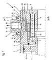
- the device shown in Figures 1 to 4 and designated 1 is used for Supply of pressure medium, for example pressure oil, from a stationary arrangement Component 2 in a two-part rotating component 3, 3 'and one on this by means Screws 8 attached hollow clamping cylinder 4.
- pressure medium for example pressure oil
- the cylinder wall forms the component 3 'is a Piston 5 acted upon by pressure medium, its associated Pressure chamber 6 via channels 7, 7 'provided in the rotating component 3, 3' Supply of the pressure medium is connected to the stationary component 2.
- the stationary component 2 designed as a disk 11 engages with a radial distance into the rotating component 3, 3 ', so that between them an axially directed annular groove 14th and on both sides of the fixed component 2 radial sealing gaps 15 and 16 are formed are.
- the disc 11 with a connection 12 for a not shown Pressure medium supply line and a channel 13, which opens into the annular groove 14, Mistake.
- the channel 7 incorporated in the rotating component 3 is on the Annular groove 14 connected so that the pressure medium supplied via the channel 13, the annular groove 14 and the channels 7 and 7 'in the pressure chamber 6 of Hollow clamping cylinder 4 arrives.
- the End faces 21 and 22 thus each have an inner sealing surface 25 and 26, respectively Pressure chambers 29 and 30 and an outer outer sealing surface 33 and 34 respectively.
- the inner ones Inner sealing surfaces 25 and 26 are dimensioned about twice as large as that Outer sealing surfaces 33 and 34. They are also acted upon in the axial direction Areas of the pressure chambers 29 and 30, which are rectangular in cross section, are larger dimensioned as the inner sealing surfaces 25 and 26. This is a short-term Leveling of the two components allows each other.
- the hollow clamping cylinder 4 via the stationary component 2 and the rotating Component 3 pressure medium supplied, so is in the pressure chamber 6 and the annular groove 14 static pressure built up.
- a subset of the pressure medium is in the in Figure 1 shown position of the two components 2 and 3 to each other on the enlarged radial sealing gap 15 into a web 17 formed on the disk 12 flow out of the formed collecting chamber 19.
- the opposite radial Sealing gap 16 by contact of the outer sealing surface 34 on the disc 12 almost is closed, but the pressure chamber 30 via the control slot 38 with the annular groove 14 is connected, a pressure is built up in this and thus an axially directed Force exerted on the two components 2 and 3.
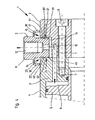
- the end faces 23 and 24 of the stationary component 2 pressure chambers 31 and 32 incorporated, the Control slots 39 and 40 are connected to the annular groove 14.
- the Inner sealing surfaces 27 and 28 and the outer sealing surfaces 35 and 36 are thus on the disk 11 of the stationary component 2, the end faces 21 and 22
- the rotating component 3, 3 ' are designed to be flat.
Landscapes
- Engineering & Computer Science (AREA)
- Mechanical Engineering (AREA)
- Joints Allowing Movement (AREA)
- Pressure Vessels And Lids Thereof (AREA)
Description
- Figur 1
- die an einen Hohlspannzylinder angebaute Druckmittelzuführungseinrichtung, in einem axialen Schnitt,
- Figur 2
- einen Schnitt nach der Linie II - II der Figur 1,
- Figur 3
- die Druckmittelzuführungseinrichtung nach Figur 1 mit an dem ortsfesten Bauteil vorgesehenen Druckkammern, und
- Figur 4
- die Druckmittelzuführungseinrichtung nach Figur 3 mit jeweils zwei konzentrisch ineinander angeordneten Druckkammern.
Claims (11)
- Einrichtung (1) zur Zuführung von Druckmittel aus einem ortsfesten Bauteil (2) in ein rotierendes Bauteil (3, 3'), insbesondere zur Zuführung von Druckmittel in einen Hohlspannzylinder 84) oder dgl., wobei zwischen dem ortsfesten Bauteil (2) und dem rotierenden Bauteil (3, 3') eine axial gerichtete Ringnut (14) sowie radial gerichtete Dichtspalte (15, 16) vorgesehen sind, und in die die radial gerichteten Dichtspalte (15, 16) begrenzenden Stirnflächen (21, 22 bzw. 23, 24) des ortsfesten Bauteils (2) und/oder des rotierenden Bauteils (3, 3') jeweils eine oder mehrere umlaufende Druckkammern (29, 30 bzw. 31, 32 bzw. 31, 31', 32, 32') eingearbeitet sind,
dadurch gekennzeichnet, daß die über einen oder mehrere radial gerichtete Regelschlitze (37, 38 bzw. 39, 40 bzw. 39, 39', 40, 40') mit der Ringnut (14) zwischen dem ortsfesten Bauteil (2) und dem rotierenden Bauteil (3, 3') verbunden sind, und daß die die radial gerichteten Dichtspalte (15, 16) begrenzenden mit den Druckkammem (29, 30 bzw. 31, 32 bzw. 31, 31', 32, 32') versehene Stirnflächen (21, 22 bzw. 23, 24) des ortsfesten Bauteils (2) und/oder des rotierenden Bauteils (3, 3') flächengleich zueinander ausgebildet sind. - Einrichtung nach Anspruch 1,
dadurch gekennzeichnet, daß die die radial gerichteten Dichtspalte (15, 16) begrenzenden mit den Druckkammern (29, 30 bzw. 31, 32 bzw. 31, 31', 32, 32') versehenen Stirnflächen (21, 22 bzw. 23, 24) des ortsfesten Bauteils (2) oder des rotierenden Bauteils (3) in bezug auf die Querachse des ortsfesten Bauteils (2) spiegelbildlich flächengleich zueinander ausgebildet sind. - Einrichtung nach Anspruch 2,
dadurch gekennzeichnet, daß die dem einen radialen Dichtspalt (15) zugeordneten Druckkammern (29) und Regelschlitze (37) in das ortsfeste Bauteil (2) oder das rotierende Bauteil (3) und die dem anderen radialen Dichtspalt (16) zugeordneten Druckkammern (32) und Regelschlitze (40) in das rotierende Bauteil (3) oder das ortsfeste Bauteil (2) eingearbeitet sind. - Einrichtung nach einem der Ansprüche 1 bis 3,
dadurch gekennzeichnet, daß die einander zugekehrten Stirnflächen (21, 22 bzw. 23, 24) des ortsfesten Bauteils (2) und/oder des rotierenden Bauteils (3, 3') jeweils mit einer flächengleichen Innendichtfläche (25, 26 bzw. 27, 28), einer oder mehreren Druckkammern (29, 30 bzw. 31, 32 bzw. 31, 31', 32, 32') sowie einer flächengleichen Außendichtfläche (33, 34 bzw. 35, 36) versehen sind. - Einrichtung nach Anspruch 4,
dadurch gekennzeichnet, daß die an den Stirnflächen (21, 22 bzw. 23, 24) des ortsfesten Bauteils (2) und/oder des rotierenden Bauteils (3, 3') vorgesehenen Innendichtflächen (25, 26 bzw. 27, 28) etwa doppelt so groß bemessen sind wie die Außendichtflächen (33, 34 bzw. 35, 36). - Einrichtung nach Anspruch 4 oder 5,
dadurch gekennzeichnet, daß die in axialer Richtung beaufschlagten Flächen der Druckkammern (29, 30 bzw. 31, 32) größer bemessen sind als die Innendichtflächen (25, 26 bzw. 27, 28) der radialen Dichtspalte (15, 16). - Einrichtung nach einem der Ansprüche 4 bis 6,
dadurch gekennzeichnet, daß die Druckkammern (29, 30 bzw. 31, 32) im Querschnitt rechteckig ausgebildet sind. - Einrichtung nach einem der Ansprüche 4 bis 7,
dadurch gekennzeichnet, daß bei zwei oder mehreren in das ortsfeste Bauteil (2) und/oder das rotierende Bauteil (3, 3') eingearbeitete Druckkammern (31, 31' bzw. 32, 32') diese jeweils über einen oder mehrere Regelschlitze (39, 39' bzw, 40, 40') mit der axial gerichteten Ringnut (14) und untereinander verbunden sind. - Einrichtung nach eiriem der Ansprüche 4 bis 8,
dadurch gekennzeichnet daß die den beiden radialen Dichtspalten (15, 16) zugeordneten Regelschlitze (37, 38 bzw. 39, 40) jeweils eine gleich groß bemessene Querschnittsfläche aufweisen. - Einrichtung nach einem der Ansprüche 1 bis 9,
dadurch gekennzeichnet, daß das ortsfeste Bauteil (2) als ringförmige Scheibe (11) ausgebildet ist und in das rotierende Bauteil (3) eingreift. - Einrichtung nach einem der Ansprüche 1 bis 10,
dadurch gekennzeichnet, daß jeder der radial gerichteten Dichtspalte (15, 16) durch eine vorzugsweise durch einen am ortsfesten Bauteil (2) angeformten Steg (17, 18) gebildete Auffangkammer (19, 20) abgedeckt ist.
Applications Claiming Priority (2)
| Application Number | Priority Date | Filing Date | Title |
|---|---|---|---|
| DE19817331A DE19817331A1 (de) | 1998-04-18 | 1998-04-18 | Druckmittelzuführungseinrichtung |
| DE19817331 | 1998-04-18 |
Publications (3)
| Publication Number | Publication Date |
|---|---|
| EP0950464A2 EP0950464A2 (de) | 1999-10-20 |
| EP0950464A3 EP0950464A3 (de) | 2002-05-02 |
| EP0950464B1 true EP0950464B1 (de) | 2003-09-03 |
Family
ID=7865024
Family Applications (1)
| Application Number | Title | Priority Date | Filing Date |
|---|---|---|---|
| EP99105900A Expired - Lifetime EP0950464B1 (de) | 1998-04-18 | 1999-03-24 | Druckmittelzuführungseinrichtung |
Country Status (4)
| Country | Link |
|---|---|
| US (1) | US6145890A (de) |
| EP (1) | EP0950464B1 (de) |
| JP (1) | JP2000028063A (de) |
| DE (2) | DE19817331A1 (de) |
Families Citing this family (3)
| Publication number | Priority date | Publication date | Assignee | Title |
|---|---|---|---|---|
| US7083200B2 (en) * | 2003-08-28 | 2006-08-01 | Focal Technologies Corporation | Fluid rotary union |
| NO323924B1 (no) | 2004-08-31 | 2007-07-23 | Atle Kvamme | Anordning ved trykkompensert svivel |
| JP6056657B2 (ja) * | 2012-06-22 | 2017-01-11 | 株式会社デンソー | 配管接続装置及びこれを有するヒートポンプサイクル装置 |
Family Cites Families (12)
| Publication number | Priority date | Publication date | Assignee | Title |
|---|---|---|---|---|
| US3392995A (en) * | 1966-08-23 | 1968-07-16 | Malan Vibrator Co Inc | Pressure balanced ball joint |
| CH584371A5 (de) * | 1974-12-03 | 1977-01-31 | Cyphelly Ivan J | |
| US4139220A (en) * | 1977-02-07 | 1979-02-13 | Fmc Corporation | Swivel joint sealing system |
| DE3004807C2 (de) * | 1980-02-09 | 1984-11-15 | SMW Schneider & Weißhaupt GmbH, 7996 Meckenbeuren | Druckmittelzuführungseinrichtung für umlaufende Spannzylinder an Werkzeugmaschinen |
| JPS5840578A (ja) * | 1981-09-04 | 1983-03-09 | Ricoh Co Ltd | クリ−ニング装置の脱着装置 |
| US4561679A (en) * | 1982-07-26 | 1985-12-31 | Exxon Production Research Co. | Seal pressure reduction system |
| DE3632677A1 (de) * | 1986-09-26 | 1988-04-07 | Berg & Co Gmbh | Umlaufender hohlspannzylinder |
| US4828292A (en) * | 1987-12-31 | 1989-05-09 | Amtel, Inc. | Adjustable fluid swivel |
| US4925219A (en) * | 1988-07-21 | 1990-05-15 | Jack Pollack | Fluid swivel assembly |
| DE4124153A1 (de) * | 1991-07-20 | 1993-01-21 | Smw Spanneinrichtungen | Einrichtung zur uebertragung eines mediums |
| DE4404547C2 (de) * | 1994-02-12 | 1997-08-28 | Thomas Hiestand | Druckmittelzuführung |
| US5720503A (en) * | 1995-11-08 | 1998-02-24 | Single Buoy Moorings Inc. | Sealing sytem--anti collapse device |
-
1998
- 1998-04-18 DE DE19817331A patent/DE19817331A1/de not_active Ceased
-
1999
- 1999-03-24 EP EP99105900A patent/EP0950464B1/de not_active Expired - Lifetime
- 1999-03-24 DE DE59906820T patent/DE59906820D1/de not_active Expired - Lifetime
- 1999-04-14 US US09/291,397 patent/US6145890A/en not_active Expired - Fee Related
- 1999-04-16 JP JP11109746A patent/JP2000028063A/ja active Pending
Also Published As
| Publication number | Publication date |
|---|---|
| JP2000028063A (ja) | 2000-01-25 |
| DE59906820D1 (de) | 2003-10-09 |
| EP0950464A2 (de) | 1999-10-20 |
| EP0950464A3 (de) | 2002-05-02 |
| US6145890A (en) | 2000-11-14 |
| DE19817331A1 (de) | 1999-10-21 |
Similar Documents
| Publication | Publication Date | Title |
|---|---|---|
| DE3914961C2 (de) | Wellendichtung mit zylindrischer dichtflaeche | |
| DE19600664B4 (de) | Dichtungsanordnung für eine Strömungsmittelkupplung bzw. Kühlmitteleinheit | |
| EP0242741B1 (de) | Dichtungsanordnung | |
| DE2855453A1 (de) | Dichtungsanordnung zwischen einem inneren teil, insbesondere einer welle, und einem diesen umgebenden aeusseren teil | |
| DE3602051A1 (de) | Waelzlager-drehverbindung | |
| DE4341167A1 (de) | Einrichtung zur Übertragung eines Druckmediums | |
| EP0525371B1 (de) | Einrichtung zur Übertragung eines Mediums | |
| EP0708267A2 (de) | Gasdruckfeder | |
| WO1991019120A1 (de) | Dichtungsanordnung | |
| EP0950464B1 (de) | Druckmittelzuführungseinrichtung | |
| DE3914552A1 (de) | Waelzlagerung | |
| EP0144786A1 (de) | Trennvorrichtung | |
| DE4338875C2 (de) | Reversierbare Innenzahnradmaschine (Pumpe oder Motor) | |
| DE2402237A1 (de) | Hydrostatisches lager | |
| DE4232191C1 (de) | Vorrichtung zum Verstellen der Exzentrizität eines exzentrischen Radiallagers | |
| EP0974782B1 (de) | Druckmittelzuführungseinrichtung | |
| DE2905631C2 (de) | Walzgerüst mit mindestens einer von einer losen drehbaren Hülse umgebenden Stützwalze | |
| DE4133262A1 (de) | Einrichtung zur uebertragung eines mediums | |
| DE3204647C2 (de) | Einrichtung zur Durchführung eines Druckmediums von einem feststehenden Gehäuse zu einer drehbaren Welle | |
| DE2409721A1 (de) | Hydrodynamische abhebung von drehschneiden und werkzeugen an drehspindeln zwecks von drehflaeche freies zurueckfahren bei umlaufender drehspindel | |
| DE2047311A1 (de) | Spindelkopf | |
| DE3942775A1 (de) | Hydraulischer schwenkmotor | |
| EP0859717B1 (de) | Abstutzung fur einen wagenkasten an einem fahrgestell | |
| DE2215450C3 (de) | Freistrahl-Servoventil | |
| DE10028336C1 (de) | Axialkolbenmaschine |
Legal Events
| Date | Code | Title | Description |
|---|---|---|---|
| PUAI | Public reference made under article 153(3) epc to a published international application that has entered the european phase |
Free format text: ORIGINAL CODE: 0009012 |
|
| AK | Designated contracting states |
Kind code of ref document: A2 Designated state(s): AT BE CH CY DE DK ES FI FR GB GR IE IT LI LU MC NL PT SE Kind code of ref document: A2 Designated state(s): AT BE CH CY DE LI |
|
| AX | Request for extension of the european patent |
Free format text: AL;LT;LV;MK;RO;SI |
|
| PUAL | Search report despatched |
Free format text: ORIGINAL CODE: 0009013 |
|
| AK | Designated contracting states |
Kind code of ref document: A3 Designated state(s): AT BE CH CY DE DK ES FI FR GB GR IE IT LI LU MC NL PT SE |
|
| AX | Request for extension of the european patent |
Free format text: AL;LT;LV;MK;RO;SI |
|
| 17P | Request for examination filed |
Effective date: 20021016 |
|
| GRAH | Despatch of communication of intention to grant a patent |
Free format text: ORIGINAL CODE: EPIDOS IGRA |
|
| AKX | Designation fees paid |
Free format text: AT BE CH CY DE LI |
|
| RBV | Designated contracting states (corrected) |
Designated state(s): CH DE FR GB IT LI |
|
| GRAH | Despatch of communication of intention to grant a patent |
Free format text: ORIGINAL CODE: EPIDOS IGRA |
|
| GRAA | (expected) grant |
Free format text: ORIGINAL CODE: 0009210 |
|
| AK | Designated contracting states |
Kind code of ref document: B1 Designated state(s): CH DE FR GB IT LI |
|
| PG25 | Lapsed in a contracting state [announced via postgrant information from national office to epo] |
Ref country code: GB Free format text: LAPSE BECAUSE OF FAILURE TO SUBMIT A TRANSLATION OF THE DESCRIPTION OR TO PAY THE FEE WITHIN THE PRESCRIBED TIME-LIMIT Effective date: 20030903 |
|
| REG | Reference to a national code |
Ref country code: GB Ref legal event code: FG4D Free format text: NOT ENGLISH |
|
| REG | Reference to a national code |
Ref country code: CH Ref legal event code: EP |
|
| REF | Corresponds to: |
Ref document number: 59906820 Country of ref document: DE Date of ref document: 20031009 Kind code of ref document: P |
|
| REG | Reference to a national code |
Ref country code: IE Ref legal event code: FG4D Free format text: GERMAN |
|
| GBV | Gb: ep patent (uk) treated as always having been void in accordance with gb section 77(7)/1977 [no translation filed] |
Effective date: 20030903 |
|
| PG25 | Lapsed in a contracting state [announced via postgrant information from national office to epo] |
Ref country code: LI Free format text: LAPSE BECAUSE OF NON-PAYMENT OF DUE FEES Effective date: 20040331 Ref country code: CH Free format text: LAPSE BECAUSE OF NON-PAYMENT OF DUE FEES Effective date: 20040331 |
|
| REG | Reference to a national code |
Ref country code: IE Ref legal event code: FD4D |
|
| ET | Fr: translation filed | ||
| PLBE | No opposition filed within time limit |
Free format text: ORIGINAL CODE: 0009261 |
|
| STAA | Information on the status of an ep patent application or granted ep patent |
Free format text: STATUS: NO OPPOSITION FILED WITHIN TIME LIMIT |
|
| 26N | No opposition filed |
Effective date: 20040604 |
|
| REG | Reference to a national code |
Ref country code: CH Ref legal event code: PL |
|
| PGFP | Annual fee paid to national office [announced via postgrant information from national office to epo] |
Ref country code: FR Payment date: 20090318 Year of fee payment: 11 |
|
| REG | Reference to a national code |
Ref country code: FR Ref legal event code: ST Effective date: 20101130 |
|
| PG25 | Lapsed in a contracting state [announced via postgrant information from national office to epo] |
Ref country code: FR Free format text: LAPSE BECAUSE OF NON-PAYMENT OF DUE FEES Effective date: 20100331 |
|
| PGFP | Annual fee paid to national office [announced via postgrant information from national office to epo] |
Ref country code: IT Payment date: 20120327 Year of fee payment: 14 |
|
| PGFP | Annual fee paid to national office [announced via postgrant information from national office to epo] |
Ref country code: DE Payment date: 20120427 Year of fee payment: 14 |
|
| REG | Reference to a national code |
Ref country code: DE Ref legal event code: R119 Ref document number: 59906820 Country of ref document: DE Effective date: 20131001 |
|
| PG25 | Lapsed in a contracting state [announced via postgrant information from national office to epo] |
Ref country code: DE Free format text: LAPSE BECAUSE OF NON-PAYMENT OF DUE FEES Effective date: 20131001 |
|
| PG25 | Lapsed in a contracting state [announced via postgrant information from national office to epo] |
Ref country code: IT Free format text: LAPSE BECAUSE OF NON-PAYMENT OF DUE FEES Effective date: 20130324 |