EP0950526A2 - Vis sans fin réglable pour changer la résolution et pour corriger d'une station à l'autre, d'une machine à l'autre ou d'un balayage à l'autre - Google Patents
Vis sans fin réglable pour changer la résolution et pour corriger d'une station à l'autre, d'une machine à l'autre ou d'un balayage à l'autre Download PDFInfo
- Publication number
- EP0950526A2 EP0950526A2 EP99201078A EP99201078A EP0950526A2 EP 0950526 A2 EP0950526 A2 EP 0950526A2 EP 99201078 A EP99201078 A EP 99201078A EP 99201078 A EP99201078 A EP 99201078A EP 0950526 A2 EP0950526 A2 EP 0950526A2
- Authority
- EP
- European Patent Office
- Prior art keywords
- lead screw
- print head
- imaging surface
- station
- image processing
- Prior art date
- Legal status (The legal status is an assumption and is not a legal conclusion. Google has not performed a legal analysis and makes no representation as to the accuracy of the status listed.)
- Withdrawn
Links
- 238000012937 correction Methods 0.000 title 1
- 238000003384 imaging method Methods 0.000 claims abstract description 71
- 238000013519 translation Methods 0.000 claims abstract description 40
- 238000012545 processing Methods 0.000 claims abstract description 27
- 230000008859 change Effects 0.000 claims abstract description 8
- 238000000034 method Methods 0.000 claims description 12
- 239000000463 material Substances 0.000 abstract description 13
- 230000005855 radiation Effects 0.000 abstract description 2
- 230000033001 locomotion Effects 0.000 description 21
- 230000008901 benefit Effects 0.000 description 9
- 230000007246 mechanism Effects 0.000 description 7
- 230000004886 head movement Effects 0.000 description 5
- 230000008878 coupling Effects 0.000 description 4
- 238000010168 coupling process Methods 0.000 description 4
- 238000005859 coupling reaction Methods 0.000 description 4
- 238000013461 design Methods 0.000 description 4
- 230000000694 effects Effects 0.000 description 4
- 238000004519 manufacturing process Methods 0.000 description 4
- 230000001419 dependent effect Effects 0.000 description 2
- 239000000835 fiber Substances 0.000 description 2
- 239000013307 optical fiber Substances 0.000 description 2
- 229920004943 Delrin® Polymers 0.000 description 1
- QJVKUMXDEUEQLH-UHFFFAOYSA-N [B].[Fe].[Nd] Chemical compound [B].[Fe].[Nd] QJVKUMXDEUEQLH-UHFFFAOYSA-N 0.000 description 1
- 239000000654 additive Substances 0.000 description 1
- 230000000996 additive effect Effects 0.000 description 1
- 230000006835 compression Effects 0.000 description 1
- 238000007906 compression Methods 0.000 description 1
- 230000026058 directional locomotion Effects 0.000 description 1
- 230000013011 mating Effects 0.000 description 1
- 238000012986 modification Methods 0.000 description 1
- 230000004048 modification Effects 0.000 description 1
- 229910001172 neodymium magnet Inorganic materials 0.000 description 1
- 229910052761 rare earth metal Inorganic materials 0.000 description 1
- 150000002910 rare earth metals Chemical class 0.000 description 1
- 238000000926 separation method Methods 0.000 description 1
- 230000001360 synchronised effect Effects 0.000 description 1
Images


Classifications
-
- B—PERFORMING OPERATIONS; TRANSPORTING
- B41—PRINTING; LINING MACHINES; TYPEWRITERS; STAMPS
- B41J—TYPEWRITERS; SELECTIVE PRINTING MECHANISMS, i.e. MECHANISMS PRINTING OTHERWISE THAN FROM A FORME; CORRECTION OF TYPOGRAPHICAL ERRORS
- B41J25/00—Actions or mechanisms not otherwise provided for
- B41J25/304—Bodily-movable mechanisms for print heads or carriages movable towards or from paper surface
-
- B—PERFORMING OPERATIONS; TRANSPORTING
- B41—PRINTING; LINING MACHINES; TYPEWRITERS; STAMPS
- B41J—TYPEWRITERS; SELECTIVE PRINTING MECHANISMS, i.e. MECHANISMS PRINTING OTHERWISE THAN FROM A FORME; CORRECTION OF TYPOGRAPHICAL ERRORS
- B41J19/00—Character- or line-spacing mechanisms
- B41J19/18—Character-spacing or back-spacing mechanisms; Carriage return or release devices therefor
- B41J19/20—Positive-feed character-spacing mechanisms
- B41J19/202—Drive control means for carriage movement
Definitions
- This invention relates to image processors in general and in particular to a laser printer having the capability to accurately adjust its linear translation mechanism relative to the image plane for the purpose of precisely adjusting the resolution of the intended image, as well as for the purpose of improving the consistency of resolution of the intended image, images machine-to-machine or, in the case of a press, station-to-station.
- U.S. Patent No. 5,268,708 discloses an image processing apparatus having half-tone color proofing capabilities.
- This image processing apparatus is arranged to form an intended image on a sheet of thermal print media by transferring dye from a sheet of dye donor material to the thermal print media by applying a sufficient amount of thermal energy to the dye donor material to form an intended image.
- a scanning subsystem or write engine provides the scanning function. This is accomplished by retaining the thermal print media and the dye donor material on the imaging drum while the drum is rotated past a print head that will expose the thermal print media.
- a translation drive then traverses the print head axially along the imaging drum, in coordinated motion with the rotating imaging drum.
- a scanning subsystem or write engine provides the scanning function by generating a once per revolution timing signal to data path electronics as a clock signal while the translation drive traverses the print head axially along the imaging drum in a coordinated motion with the imaging drum rotating past the print head. This is done with positional accuracy maintained, to allow precise control of the placement of each pixel, in order to produce the intended image on the thermal print media.
- Image resolution that is, dots imaged per inch
- the ability to vary image resolution slightly is an advantage in that it can help to alleviate banding, moire, and other imaging effects that may occur in an image when that image is reproduced at a specific resolution. Slight changes to resolution can eliminate these effects without objectionable changes to overall image reproduction.
- Dimensional factors include pixel-to-pixel distance (chiefly a function of print head optics and laser diode arrangement), number of lasers used (which, in turn, determines the swath width), pitch of the lead screw, and writing drum circumference.
- Timing factors include drum rotation speed and the linear motion of the print head as it moves along the writing drum.
- the print head linear motion is itself a factor of the rotational speed of the drive motor for the lead screw and lead screw pitch.
- the capability to vary this speed for precision operation over a range of values requires an expensive motor and it can be difficult to maintain consistent results using this method.
- the ability to alter the imaging resolution and swath width for multiple values requires the ability to adjust both dimensional and timing characteristics of the image processing apparatus.
- the present invention is directed to overcoming one or more of the problems set forth above.
- the invention provides a lead screw drive mechanism that operates at an angle relative to the print head translation path to thereby effectively changes the speed of the print head in its path along the drum, allowing adjustment of head translation for a range of different image resolutions, swath widths, and swath-to-swath dimensions without altering the drive motor speed.
- Making the angular adjustment variable over a range of angles allows fine-tuning of image resolution and swath-to-swath dimensions with a single mechanical adjustment.
- FIG. 1 there is illustrated a perspective view of a lathe bed scanning subsystem 200 of an image processing apparatus, including a vacuum imaging drum 300, a print head 500 and a lead screw 250 assembled in a lathe bed scanning frame 202.
- Vacuum imaging drum 300 is mounted for rotation about an axis 301 in lathe bed scanning frame 202.
- Print head 500 is movable with respect to vacuum imaging drum 300, and is arranged to direct a beam of light to a dye donor sheet material.
- the beam of light from print head 500 is modulated individually by modulated electronic signals from an image processing apparatus so that the color on the dye donor sheet material is heated to cause volatilization only in those areas in which its presence is required on thermal print media 32 to reconstruct the shape and color of the original image.
- the print head includes a plurality of laser diodes which are coupled to the print- head by fiber optic cables which can be individually modulated to supply energy to selected areas of the thermal print media in accordance with an information signal.
- the print head of the image processing apparatus includes a plurality of optical fibers coupled to the laser diodes at one end and the other end to a fiber optic array within the print head.
- the print head is movable relative to the longitudinal axis of the vacuum imaging drum.
- the dye is transferred to the thermal print media as the radiation, transferred from the laser diodes by the optical fibers to the print head and thus to the dye donor material, is converted to thermal energy in the dye donor material.
- the print head writes using multiple lasers at a time, so that it writes the image onto the receiving medium (which is mounted on the imaging drum) as a series of adjacent, parallel swaths.
- Print head 500 is mounted on a movable translation stage member 220 which, in turn, is supported for low friction slidable movement on translation bearing rods 206 (rear) and 208 (front).
- Translation bearing rods 206 and 208 are as sufficiently rigid as possible so as not to sag or distort between their mounting points and are arranged as parallel as possible with axis 301 of vacuum imaging drum 300 in order to maintain the axis of print head 500 so that it is perpendicular to axis 301 of vacuum imaging drum 300.
- Front translation bearing rod 208 locates translation stage member 220 in the vertical and the horizontal directions with respect to axis 301 of vacuum imaging drum 300.
- Rear translation bearing rod 206 locates translation stage member 220 only with respect to rotation of translation stage member 220 about front translation bearing rod 208 so that there is no over-constraint condition of translation stage member 220 which might cause it to bind, chatter, or otherwise impart undesirable vibration or jitters to print head 500 during the generation of an intended image.
- the translation drive is for permitting relative movement of the print head by synchronizing the motion of the print head and stage assembly such that the required movement is made smoothly and evenly throughout each rotation of the drum.
- a clock signal generated by a drum encoder provides the necessary reference signal accurately indicating the position of the drum.
- This coordinated motion results in the print head tracing out a helical pattern around the periphery of the drum.
- the above mentioned motion is accomplished by means of a dc. servo motor and encoder which rotates a lead screw that is, typically, aligned parallel with the axis of the vacuum imaging drum.
- the print head is placed on the translation stage member in a "V" shaped groove, which is formed in the translation stage member, which is in precise positional relationship to the bearings for the front translation stage member supported by the front and rear translation bearing rods.
- the translation bearing rods are positioned parallel to the vacuum imaging drum, so that the print head automatically adopts the preferred orientation with respect to the surface of the vacuum imaging drum.
- the print head is selectively locatable with respect to the translation stage member, thus it is positioned with respect to the vacuum imaging drum surface.
- the translation stage member and print head are attached to a rotatable lead screw (having a threaded shaft) by a drive nut and coupling.
- the coupling is arranged to accommodate misalignment of the drive nut and lead screw so that only rotational forces and forces parallel to the lead screw are imparted to the translation stage member by the lead screw and drive nut.
- the lead screw rests between two sides of the lathe bed scanning frame of the lathe bed scanning subsystem or write engine, where it is supported by deep groove radial bearings. At the drive end the lead screw continues through the deep groove radial bearing, through a pair of spring retainers, that are separated and loaded by a compression spring to provide axial loading, and to a DC. servo drive motor and encoder. The DC.
- servo drive motor induces rotation to the lead screw moving the translation stage member and print head along the threaded shaft as the lead screw is rotated.
- the lateral directional movement of the print head is controlled by switching the direction of rotation of the DC. servo drive motor and thus the lead screw.
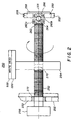
- a lead screw 250 which includes an elongated, threaded shaft 252 which is attached to a linear drive motor 258 on its drive end and to lathe bed scanning frame 202 by means of a radial bearing 272.
- a lead screw drive nut 254 includes grooves in its hollowed-out center portion 270 for mating with the threads of threaded shaft 252 for permitting lead screw drive nut 254 to move axially along threaded shaft 252 as threaded shaft 252 is rotated by linear drive motor 258.
- Lead screw drive nut 254 is integrally attached to the to print head 500 through lead screw coupling and to translation stage member 220 at its periphery so that, as threaded shaft 252 is rotated by linear drive motor 258, lead screw drive nut 254 moves axially along threaded shaft 252 which in turn moves translation stage member 220 and ultimately print head 500 axially along vacuum imaging drum 300.
- the print head moves in the "slow scan” direction, along the vacuum imaging drum in a path that is parallel to the longitudinal axis of the vacuum imaging drum.
- the linear motion system moves the print head in this slow scan direction, from a home position to the start-of-scan point (where it begins writing the image data) and across, to the opposite end of the drum.
- the combined movement of the print head in the slow scan direction and the vacuum imaging drum (in the "fast scan” direction) perpendicular to the motion of the print head causes the image to be written in a helix pattern about the vacuum imaging drum.
- annular-shaped axial load magnet 260a is integrally attached to the driven end of threaded shaft 252, and is in a spaced apart relationship with another annular-shaped axial load magnet 260b attached to a movable end plate 230 that is locked into position on lathe bed scanning frame 202 by set screw 228.
- Axial load magnets 260a and 260b are preferably made of rare-earth materials such as neodymium-iron-boron.
- a generally circular-shaped boss 262 part of threaded shaft 252 rests in the hollowed-out portion of annular-shaped axial load magnet 260a, and includes a generally V-shaped surface at the end for receiving a ball bearing 264.
- a circular-shaped insert 266 is placed in the hollowed-out portion of the other annular-shaped axial load magnet 260b, and includes an accurate-shaped surface on one end for receiving ball bearing 264, and a flat surface at its other end for receiving an end cap 268 placed over annular-shaped axial load magnet 260b and attached to movable end plate 230 for protectively covering annular-shaped axial load magnet 260b and providing an axial stop for lead screw 250.
- Circular shaped insert 266 is preferably made of material such as Rulon J or Delrin AF, both well known in the art.
- Lead screw 250 operates as follows. Linear drive motor 258 is energized and imparts rotation to lead screw 250, as indicated by the arrows, causing lead screw drive nut 254 to move axially along threaded shaft 252. Annular-shaped axial load magnets 260a and 260b are magnetically attracted to each other which prevents axial movement of lead screw 250. Ball bearing 264, however, permits rotation of lead screw 250 while maintaining the positional relationship of annular-shaped axial load magnets 260, i.e., slightly spaced apart, which prevents mechanical friction between them while permitting threaded shaft 252 to rotate.
- Print head 500 travels in a path along vacuum imaging drum 300, while being moved at a speed synchronous with vacuum imaging drum 300 rotation and proportional to the width of writing swath.
- the pattern that print head 500 transfers to thermal print media 32 along the vacuum imaging drum 300, is a helix.
- angular adjustment of lead screw 250 relative to vacuum drum 300 axis 301 is set at the drive end, where lead screw 250 is mounted on lathe bed scanning frame 202.
- An adjustable collar 232 that retains radial bearing 272 is bolted into position on lathe bed scanning frame 202. This allows this end of lead screw 250 to be moved along frame 202 so that lead screw 250 can be adjusted to be at some angle other than a right angle relative to frame 202.
- lead screw 250 is out of parallel with respect to front translation rod 208 by offset angle 234.
- translation stage member 220 still moves in a path parallel to the drum axis. Only lead screw 250 itself is out of parallel.
- translation stage member 220 moves parallel to vacuum imaging drum 300 at a speed that is proportional to the speed that translation stage member 220 would have if lead screw 250 were parallel with respect to the front translation rod 208.
- the new speed (that is, with lead screw 250 at an angle) is the product of the baseline speed (that is, the speed if lead screw 250 were in parallel) times the cosine of the offset angle 234. (For example, for a 1° angle offset from parallel, the speed of the translation stage member 220 would equal 0.9998 times the baseline speed, since 0.9998 is the approximate cosine of 1° angle.)
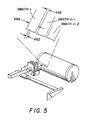
- print head 500 writes with multiple lasers at a time, forming a writing swath 450 that images in a continuous helix.
- print head 500 is moved along from its start position 456 at one end of vacuum imaging drum 300 to its end position 458 at the other end of vacuum imaging drum 300 by translation stage member 220.
- FIG. 5 shows how the pixel-to-pixel distance 452 and swath-to-swath distance 448 are related. Any change in pixel-to-pixel distance 452 will affect swath width 446 (unless a different number of writing lasers are used and the same swath width 446 is maintained). Any change to swath width 446 requires a corresponding change to the traversal speed of print head 500 so that the distance between adjacent swaths in the helix is the same as the pixel-to-pixel distance 452. (Otherwise, banding can occur in the output image.)
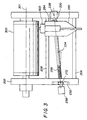
- FIG. 6 shows one possible arrangement with several imaging stations built into a multiple-station image processing apparatus 462.
- Each station 460 has its own print head 500 and vacuum imaging drum 300 with the corresponding support components noted in the above detailed description.
- the media being imaged would be transported from station 460 to station 460, with each station 460 imaging with a different color.
- the invention has been described with reference to the preferred embodiment thereof. However, it will be appreciated and understood that variations and modifications can be effected within the spirit and scope of the invention as described herein above and as defined in the appended claims by a person of ordinary skill in the art without departing from the scope of the invention.
- the invention is applicable to any imaging apparatus that uses a lead screw for print head positioning.
- the movable end of the lead screw can be moved in any direction to provide the necessary offset from parallel, allowing this method to be used where space is at a premium.
- the imaging surface may be a drum as described, or any other suitable surface such as a web or platen; curved or flat.
Landscapes
- Character Spaces And Line Spaces In Printers (AREA)
- Electronic Switches (AREA)
- Manufacture Or Reproduction Of Printing Formes (AREA)
- Facsimile Scanning Arrangements (AREA)
Applications Claiming Priority (2)
| Application Number | Priority Date | Filing Date | Title |
|---|---|---|---|
| US60605 | 1998-04-15 | ||
| US09/060,605 US5973717A (en) | 1998-04-15 | 1998-04-15 | Adjustable lead screw for changing resolution and for station-to-station, machine-to-machine, or swath-to-swath corrections |
Publications (2)
| Publication Number | Publication Date |
|---|---|
| EP0950526A2 true EP0950526A2 (fr) | 1999-10-20 |
| EP0950526A3 EP0950526A3 (fr) | 2000-06-14 |
Family
ID=22030584
Family Applications (1)
| Application Number | Title | Priority Date | Filing Date |
|---|---|---|---|
| EP99201078A Withdrawn EP0950526A3 (fr) | 1998-04-15 | 1999-04-06 | Vis sans fin réglable pour changer la résolution et pour corriger d'une station à l'autre, d'une machine à l'autre ou d'un balayage à l'autre |
Country Status (2)
| Country | Link |
|---|---|
| US (1) | US5973717A (fr) |
| EP (1) | EP0950526A3 (fr) |
Cited By (2)
| Publication number | Priority date | Publication date | Assignee | Title |
|---|---|---|---|---|
| GB2354737A (en) * | 1999-09-30 | 2001-04-04 | Eastman Kodak Co | A colour proofing apparatus and method of writing inkjet images on an intermediate ink receiving element |
| CN103921562A (zh) * | 2014-04-29 | 2014-07-16 | 成都中牧生物药业有限公司 | 一种药品包装盒打码装置 |
Families Citing this family (10)
| Publication number | Priority date | Publication date | Assignee | Title |
|---|---|---|---|---|
| US6819448B2 (en) * | 1998-09-28 | 2004-11-16 | Hewlett-Packard Development Company, L.P. | Printer with print mode masking periodic carriage vibration |
| US6222569B1 (en) * | 1998-12-21 | 2001-04-24 | Eastman Kodak Company | Laser thermal printer with dual direction imaging |
| US6535305B1 (en) * | 2000-01-12 | 2003-03-18 | Umax Data Systems Inc. | Transmission mechanism for optical scanner |
| JP2001322234A (ja) * | 2000-05-17 | 2001-11-20 | Komori Corp | 印刷機 |
| US7012629B2 (en) * | 2001-09-25 | 2006-03-14 | Fuji Photo Film Co., Ltd. | Temperature compensating image recording device |
| US6614463B2 (en) * | 2001-10-05 | 2003-09-02 | Eastman Kodak Company | Image processing apparatus with conduit tube and blower |
| JP2010137489A (ja) * | 2008-12-15 | 2010-06-24 | Seiko Epson Corp | 記録位置補正装置、記録位置補正装置の制御方法、及び記録装置 |
| TW201348006A (zh) * | 2012-05-30 | 2013-12-01 | Hon Hai Prec Ind Co Ltd | 噴墨頭調節裝置及方法 |
| US9007598B1 (en) | 2013-11-14 | 2015-04-14 | Honeywell International Inc. | Minimally-threaded screw to reduce alignment shifts |
| CN103921578B (zh) * | 2014-04-29 | 2016-02-03 | 成都中牧生物药业有限公司 | 一种易于调整活字相对于色带行程的药品包装盒打码机 |
Citations (4)
| Publication number | Priority date | Publication date | Assignee | Title |
|---|---|---|---|---|
| US4270155A (en) | 1979-06-28 | 1981-05-26 | Basf Aktiengesellschaft | Transducer positioning apparatus |
| US4313143A (en) | 1979-09-04 | 1982-01-26 | Minnesota Mining And Manufacturing Co. | Head positioning mechanism for data cartridge recorder |
| US4747004A (en) | 1986-04-07 | 1988-05-24 | Archive Corporation | Magnetic head positioning apparatus |
| US5268708A (en) | 1991-08-23 | 1993-12-07 | Eastman Kodak Company | Laser thermal printer with an automatic material supply |
Family Cites Families (6)
| Publication number | Priority date | Publication date | Assignee | Title |
|---|---|---|---|---|
| US33661A (en) * | 1861-11-05 | Washing-machine | ||
| US3853024A (en) * | 1973-10-29 | 1974-12-10 | Ibm | Two speed drive system for print mechanism or the like |
| SE8402057L (sv) * | 1984-04-12 | 1985-10-13 | Ericsson Telefon Ab L M | Legesavkenningsanordning for ett av en motor drivet fram- och atergaende organ |
| USRE33661E (en) | 1986-04-25 | 1991-08-13 | Archive Corporation | Head positioning assembly |
| JPH09214684A (ja) * | 1995-12-01 | 1997-08-15 | Oki Data:Kk | 複写装置と画像読取機と画像記録機 |
| US5838345A (en) * | 1996-06-21 | 1998-11-17 | Eastman Kodak Company | Apparatus for maintaining the positional relationship of a print head |
-
1998
- 1998-04-15 US US09/060,605 patent/US5973717A/en not_active Expired - Fee Related
-
1999
- 1999-04-06 EP EP99201078A patent/EP0950526A3/fr not_active Withdrawn
Patent Citations (4)
| Publication number | Priority date | Publication date | Assignee | Title |
|---|---|---|---|---|
| US4270155A (en) | 1979-06-28 | 1981-05-26 | Basf Aktiengesellschaft | Transducer positioning apparatus |
| US4313143A (en) | 1979-09-04 | 1982-01-26 | Minnesota Mining And Manufacturing Co. | Head positioning mechanism for data cartridge recorder |
| US4747004A (en) | 1986-04-07 | 1988-05-24 | Archive Corporation | Magnetic head positioning apparatus |
| US5268708A (en) | 1991-08-23 | 1993-12-07 | Eastman Kodak Company | Laser thermal printer with an automatic material supply |
Cited By (4)
| Publication number | Priority date | Publication date | Assignee | Title |
|---|---|---|---|---|
| GB2354737A (en) * | 1999-09-30 | 2001-04-04 | Eastman Kodak Co | A colour proofing apparatus and method of writing inkjet images on an intermediate ink receiving element |
| GB2354737B (en) * | 1999-09-30 | 2003-02-19 | Eastman Kodak Co | A colour proofing apparatus and method for writing inkjet images to an intermediate ink receiving element |
| CN103921562A (zh) * | 2014-04-29 | 2014-07-16 | 成都中牧生物药业有限公司 | 一种药品包装盒打码装置 |
| CN103921562B (zh) * | 2014-04-29 | 2016-03-23 | 成都中牧生物药业有限公司 | 一种药品包装盒打码装置 |
Also Published As
| Publication number | Publication date |
|---|---|
| US5973717A (en) | 1999-10-26 |
| EP0950526A3 (fr) | 2000-06-14 |
Similar Documents
| Publication | Publication Date | Title |
|---|---|---|
| US5973717A (en) | Adjustable lead screw for changing resolution and for station-to-station, machine-to-machine, or swath-to-swath corrections | |
| DE3884271T2 (de) | Gerät zur Multibilderzeugung. | |
| US4816844A (en) | Superimposed image forming apparatus | |
| US4070089A (en) | Two dimensional laser scanner with movable cylinder lens | |
| US5760817A (en) | Laser printer with apparatus to reduce banding by servo adjustment of a scanned laser beam | |
| US6249300B1 (en) | Method and apparatus for positioning a writing assembly of an image processing apparatus | |
| EP0552926A2 (fr) | Appareil à imprimer à couleurs par une révolution | |
| JPS6248861A (ja) | アレイ走査装置 | |
| DE69222604T2 (de) | Aufzeichnungsabtaster mit Steuerung der Punktposition in der Nebenabtastrichtung | |
| US5997119A (en) | Magnetic arrangement for printhead positioning in an image processing apparatus | |
| EP0977422A2 (fr) | Source de lumière multi-faisceaux, dispositif de balayage multi-faisceaux et appareil de formation d'images | |
| EP0268642A1 (fr) | Imprimante sur film photographique a haute definition | |
| DE60201113T2 (de) | Farbbilderzeugungsgerät | |
| US6049348A (en) | Programmable gearing control of a leadscrew for a printhead having a variable number of channels | |
| US6057867A (en) | Laser printer with piezoelectric apparatus to reduce banding by adjustment of a scanned laser beam | |
| US7484827B2 (en) | Image forming method and apparatus, and a recording medium storing a program for performing an image forming method | |
| US5818497A (en) | Apparatus for magnetically coupling a lead screw to a print head | |
| GB2129650A (en) | A method and machine for scanning and recording a picture | |
| US5829889A (en) | Method and apparatus for magnetically preloading a ball bearing assembly | |
| US6064170A (en) | Method of controlling a printhead movement based on a screw pitch to minimize swath-to-swath error in an image processing apparatus | |
| US5812175A (en) | Laser thermal printer with reversible imaging drum rotation for printing mirror images | |
| JPH0439054B2 (fr) | ||
| US6100911A (en) | Method and apparatus to provide a loading force print-head adjustment using magnets | |
| US6313859B1 (en) | Method and apparatus for axial direction sheet feed to a vacuum drum | |
| US6396524B1 (en) | Skew adjustment for optical writer in a document printer/copier |
Legal Events
| Date | Code | Title | Description |
|---|---|---|---|
| PUAI | Public reference made under article 153(3) epc to a published international application that has entered the european phase |
Free format text: ORIGINAL CODE: 0009012 |
|
| AK | Designated contracting states |
Kind code of ref document: A2 Designated state(s): DE FR GB |
|
| AX | Request for extension of the european patent |
Free format text: AL;LT;LV;MK;RO;SI |
|
| PUAL | Search report despatched |
Free format text: ORIGINAL CODE: 0009013 |
|
| AK | Designated contracting states |
Kind code of ref document: A3 Designated state(s): AT BE CH CY DE DK ES FI FR GB GR IE IT LI LU MC NL PT SE |
|
| AX | Request for extension of the european patent |
Free format text: AL;LT;LV;MK;RO;SI |
|
| RIC1 | Information provided on ipc code assigned before grant |
Free format text: 7B 41J 19/20 A |
|
| 17P | Request for examination filed |
Effective date: 20001201 |
|
| AKX | Designation fees paid |
Free format text: DE FR GB |
|
| 17Q | First examination report despatched |
Effective date: 20041007 |
|
| GRAP | Despatch of communication of intention to grant a patent |
Free format text: ORIGINAL CODE: EPIDOSNIGR1 |
|
| STAA | Information on the status of an ep patent application or granted ep patent |
Free format text: STATUS: THE APPLICATION IS DEEMED TO BE WITHDRAWN |
|
| 18D | Application deemed to be withdrawn |
Effective date: 20060117 |