EP0950529A2 - Blattzuführgerät und Bildformungsgerät mit einem solchen Blattzuführgerät - Google Patents
Blattzuführgerät und Bildformungsgerät mit einem solchen Blattzuführgerät Download PDFInfo
- Publication number
- EP0950529A2 EP0950529A2 EP99107281A EP99107281A EP0950529A2 EP 0950529 A2 EP0950529 A2 EP 0950529A2 EP 99107281 A EP99107281 A EP 99107281A EP 99107281 A EP99107281 A EP 99107281A EP 0950529 A2 EP0950529 A2 EP 0950529A2
- Authority
- EP
- European Patent Office
- Prior art keywords
- sheet feeding
- printer
- sheet
- recording apparatus
- asf
- Prior art date
- Legal status (The legal status is an assumption and is not a legal conclusion. Google has not performed a legal analysis and makes no representation as to the accuracy of the status listed.)
- Granted
Links
- 230000001105 regulatory effect Effects 0.000 claims abstract description 14
- 230000007246 mechanism Effects 0.000 claims description 43
- 101100492406 Caenorhabditis elegans unc-85 gene Proteins 0.000 description 125
- 101100436058 Neurospora crassa (strain ATCC 24698 / 74-OR23-1A / CBS 708.71 / DSM 1257 / FGSC 987) asf-1 gene Proteins 0.000 description 125
- 230000002441 reversible effect Effects 0.000 description 35
- 229920001971 elastomer Polymers 0.000 description 29
- 238000012840 feeding operation Methods 0.000 description 19
- 238000003780 insertion Methods 0.000 description 15
- 230000037431 insertion Effects 0.000 description 15
- 230000000694 effects Effects 0.000 description 13
- 230000002093 peripheral effect Effects 0.000 description 13
- 230000001360 synchronised effect Effects 0.000 description 10
- 230000001276 controlling effect Effects 0.000 description 8
- 230000003405 preventing effect Effects 0.000 description 7
- 238000000926 separation method Methods 0.000 description 5
- 238000011144 upstream manufacturing Methods 0.000 description 5
- 238000004891 communication Methods 0.000 description 4
- 238000010276 construction Methods 0.000 description 4
- 230000005540 biological transmission Effects 0.000 description 3
- 238000007599 discharging Methods 0.000 description 3
- 239000002985 plastic film Substances 0.000 description 3
- 229920006255 plastic film Polymers 0.000 description 3
- 230000000994 depressogenic effect Effects 0.000 description 2
- 238000010586 diagram Methods 0.000 description 2
- 238000000034 method Methods 0.000 description 2
- 238000003032 molecular docking Methods 0.000 description 2
- 239000000758 substrate Substances 0.000 description 2
- 206010040007 Sense of oppression Diseases 0.000 description 1
- 230000002159 abnormal effect Effects 0.000 description 1
- 239000011248 coating agent Substances 0.000 description 1
- 238000000576 coating method Methods 0.000 description 1
- 230000003247 decreasing effect Effects 0.000 description 1
- 230000000881 depressing effect Effects 0.000 description 1
- 230000005611 electricity Effects 0.000 description 1
- 230000007613 environmental effect Effects 0.000 description 1
- 230000003203 everyday effect Effects 0.000 description 1
- 239000004744 fabric Substances 0.000 description 1
- 238000009434 installation Methods 0.000 description 1
- 238000004519 manufacturing process Methods 0.000 description 1
- 239000000463 material Substances 0.000 description 1
- 230000003287 optical effect Effects 0.000 description 1
- 230000036961 partial effect Effects 0.000 description 1
- 230000002829 reductive effect Effects 0.000 description 1
- 230000000979 retarding effect Effects 0.000 description 1
- 230000003068 static effect Effects 0.000 description 1
- 230000008961 swelling Effects 0.000 description 1
- 229920002803 thermoplastic polyurethane Polymers 0.000 description 1
- 230000032258 transport Effects 0.000 description 1
Images















Classifications
-
- B—PERFORMING OPERATIONS; TRANSPORTING
- B41—PRINTING; LINING MACHINES; TYPEWRITERS; STAMPS
- B41J—TYPEWRITERS; SELECTIVE PRINTING MECHANISMS, i.e. MECHANISMS PRINTING OTHERWISE THAN FROM A FORME; CORRECTION OF TYPOGRAPHICAL ERRORS
- B41J13/00—Devices or arrangements of selective printing mechanisms, e.g. ink-jet printers or thermal printers, specially adapted for supporting or handling copy material in short lengths, e.g. sheets
- B41J13/10—Sheet holders, retainers, movable guides, or stationary guides
- B41J13/103—Sheet holders, retainers, movable guides, or stationary guides for the sheet feeding section
Definitions
- the present invention relates to a sheet feeding apparatus for feeding a recording medium to a recording apparatus and an image forming apparatus having such a sheet feeding apparatus, and more particularly, it relates to mounting of the recording apparatus.
- Related Background Art Similar to many other equipments, compactness and light-weighted requirements for a recording apparatus (referred to as “printer” hereinafter) have been sought greatly, and, thus, printers have been made compact and light-weighted.
- an ASF which can detachably be mounted, from outside, to a printer having a plurality of sheet feeding openings or a printer in which only manual sheet insertion is permitted, as well as the compact printer.
- the ASF essentially has a concept that it is to be mounted to the printer, and, thus, the printer is a principal part on the desk exceedingly. That is to say, since the conventional ASF cannot perform a function for automatically feeding the sheet by itself only, the ASF can have any form.
- the only ASF may not be operated by itself or may not be operated in a condition that recording media (referred to as "sheets" hereinafter) are set therein.
- a drive transmitting means (such as a gear) exposed out of the ASF is connected to a drive transmitting means exposed out of the printer so that a motor disposed within the printer can be used as a drive source for a sheet feed roller for feeding the sheets one by one.
- a control means disposed within the printer imparts a control signal to a motor disposed within the ASF through electric contacts between the printer and the ASF to rotate the motor of the ASF.
- Fig. 39 is a perspective view showing a printer body of a printer 1000 disclosed in the above Japanese Patent Application Laid-open No. 4-303336 and an ASF to be mounted to the printer body from outside, in a separated condition.
- the ASF 1047 has left and right hooks 1016, 1017 to be inserted into hook fitting holes 1103y, 1103z of the printer body 1101, and the left and right hooks 1016, 1017 can be rotated by sliding operation portions 1016c (only one is shown) provided on left and right side surfaces of the ASF 1047.
- the left and right hooks 1016, 1017 inserted into the hook fitting holes 1103y, 1103z are rotated by sliding the left and right operation portions 1016c in directions shown by the arrows L1016X, L1017X to engage the ASF 1047 with the printer body 1101, thereby securing the ASF to the printer body.
- the left and right hooks 1016, 1017 are rotated in directions opposite to the directions for engagement between the ASF 1047 and the printer body 1101 by sliding the left and right operation portions 1016c in directions opposite to the directions shown by the arrows L1016X, L1017X, thereby separating the ASF 1047 from the printer body 1101.
- the hooks 1016, 1017 since the two hooks 1016, 1017 are independently rotated, the hooks 1016, 1017 must be rotated independently in order to separate the ASF 1047 from the printer body 1101, thereby worsening operability. Further, when the ASF 1047 is connected to the printer body 1101, it cannot be ascertained whether such connection is effected properly.
- the printer body and/or the ASF may be damaged.
- the present invention aims to eliminate the above-mentioned conventional drawbacks, and an object of the present invention is to provide an ASF (sheet feeding apparatus) and an image forming apparatus having such an ASF, in which excellent mounting ability can be achieved and damage and disengagement of a mounted printer (recording apparatus) can be prevented so that the printer (recording apparatus) having excellent portable ability can be used properly as a desk-top printer having excellent sheet feeding ability on the desk.
- ASF sheet feeding apparatus
- an image forming apparatus having such an ASF
- the present invention provides a sheet feeding apparatus to which a recording apparatus capable of recording an image on a recording medium by itself can detachably be mounted and which is adapted to feed the recording medium to the mounted recording apparatus, and comprising a recording apparatus supporting portion for supporting the recording apparatus for movement in a mounting direction when the recording apparatus is mounted.
- the sheet feeding apparatus may further comprise an eaves portion disposed in parallel with the recording apparatus supporting portion and adapted to regulate an upper shifting movement of the recording apparatus when and after the recording apparatus is mounted.
- a length of the recording apparatus supporting portion in the mounting direction may be a length capable of forming a space having a predetermined mounting direction length below the recording apparatus when the recording apparatus is mounted.
- the length L2 of the recording apparatus supporting portion in the mounting direction for forming the space below the recording apparatus may have the following relationship with respect to a length L1 of the recording apparatus in the mounting direction: L1/2 ⁇ L2 ⁇ L1 - 15 mm.
- the relationship "L1/2 ⁇ L2 ⁇ L1 - 15 mm" may be satisfied at at least a part of the recording apparatus supporting portion in a direction perpendicular to the mounting direction.
- a length L3 of the eaves portion in the mounting direction may have the following relationship with respect to the length L1 of the recording apparatus in the mounting direction: L1/4 ⁇ L3 ⁇ L1/2.
- the relationship "L1/4 ⁇ L3 ⁇ L1/2" may be satisfied at at least a part of the eaves portion in a direction perpendicular to the mounting direction.
- the recording apparatus supporting portion may have sliding portions for slidingly contacting with the recording apparatus at both ends thereof in the direction perpendicular to the mounting direction, and a stepped portion may be provided between the sliding portions.
- the stepped portion may have a position and depth so that the recording apparatus supporting portion is not contacted with projections protruded from a lower surface of the recording apparatus when the recording apparatus is shifted in the mounting direction.
- the present invention further provides an image forming apparatus including a recording apparatus and a sheet feeding apparatus to which the recording apparatus can detachably be mounted and which is adapted to feed a recording medium to the mounted recording apparatus, wherein the sheet feeding apparatus is the aforementioned sheet feeding apparatus.
- the recording apparatus when the recording apparatus is mounted, after the recording apparatus is rested on the recording apparatus supporting portion for shifting movement in the mounting direction, the recording apparatus is shifted along the recording apparatus supporting portion. Further, by the eaves portion disposed substantially in parallel with the recording apparatus supporting portion, the upper movement of the recording apparatus is regulated.
- the present invention aims to eliminate the above-mentioned conventional drawbacks, and an object of the present invention is to provide a sheet feeding apparatus and an image forming apparatus, in which mounting and dismounting between a body of the apparatus and a recording apparatus can easily be performed.
- a further object of the present invention is to provide a sheet feeding apparatus and an image forming apparatus, in which non-detachment between a circular hole and a first pin is prevented, and positioning means and electrical connecting portions can be prevented from being damaged.
- the present invention provides a sheet feeding apparatus having an apparatus body to which a recording apparatus capable of recording an image on a sheet by itself can detachably be mounted and adapted to feed the sheet to the recording apparatus mounted to the apparatus body, and comprising a connecting means including an elongated hole formed in one of the recording apparatus and the apparatus body and adapted to connect the recording apparatus to the apparatus body, a pin provided on the other of the recording apparatus and the apparatus body and adapted to be connected to the elongated hole, and a connection releasing member provided on either one of the recording apparatus or the apparatus body and biased toward a connection releasing direction, and wherein an electrical connecting portion of the recording apparatus or the apparatus body is disposed at a pin side between the connection releasing member and the pin.
- the sheet feeding apparatus may further comprise a lock means provided on either one of the recording apparatus or the apparatus body and adapted to be connected to the other of the recording apparatus and the apparatus body, and be characterized in that, after the connection between the recording apparatus and the apparatus body effected by the lock means is released, the connection releasing member is operated toward the connection releasing direction, thereby releasing the connection between the elongated hole and the pin.
- the sheet feeding apparatus may further comprise a protruded member at a side of connection between the elongated hole and the pin, and, after the connection between the recording apparatus and the apparatus body effected by the lock means is released, the connection releasing member is operated toward the connection releasing direction, thereby releasing the connection between the elongated hole and the pin and operating the protruded member.
- the present invention provides a sheet feeding apparatus having an apparatus body to which a recording apparatus capable of recording an image on a sheet by itself can detachably be mounted and adapted to feed the sheet to the recording apparatus mounted to the apparatus body, and comprising connecting means including a circular hole and an elongated hole formed in one of the recording apparatus and the apparatus body and adapted to connect the recording apparatus to the apparatus body, first and second pins provided on the other of the recording apparatus and the apparatus body and adapted to be connected to the circular hole and the elongated hole, respectively, and first and second connection releasing members provided in the vicinity of the first and second pins and biased toward a connection releasing direction, and wherein the connecting means is designed so as to release the connection between the circular hole and the first pin before the connection between the elongated hole and the second pin is released, and electrical connecting portions of the recording apparatus and the apparatus body are disposed in the vicinity of the second pin between the first and second pins.
- a ratio between a distance X1 from the second pin to the electrical connecting portions and a distance X2 from the second pin to the first connection releasing member may be 0.5 or less.
- the second connection releasing member may be spaced apart from the connecting position between the circular hole and the first pin more than the electrical connecting portions.
- the present invention further provides an image forming apparatus comprising the aforementioned sheet feeding apparatus, and a recording apparatus for recording an image on the sheet conveyed from the sheet feeding apparatus.
- the electrical connecting portions of the recording apparatus and the apparatus body are disposed in the vicinity of the pin rather than the connection releasing member between the pin and the connection releasing member, and the connection between the recording apparatus and the apparatus body is released by using the connecting position between the elongated hole and the pin as a pivot center.
- the electrical connecting portions of the recording apparatus and the apparatus body are disposed in the vicinity of the second pin between the first and second pins, and the connection between the circular hole and the first pin is released before the connection between the elongated hole and the second pin is released.
- a still further object of the present invention is to provide an image forming apparatus in which connection and disconnection between a sheet feeding apparatus and a recording apparatus can be effected by a simple operation.
- a further object of the present invention is to provide an image forming apparatus in which connection between a sheet feeding apparatus and a recording apparatus can be ascertained.
- an object of the present invention aims to eliminate the above-mentioned conventional drawbacks, and an object of the present invention is to provide an image forming apparatus comprising a sheet feeding apparatus for feeding a sheet and a recording apparatus for recording an image on the sheet fed by the sheet feeding apparatus, the sheet feeding apparatus and the recording apparatus being capable of being separated from each other, and wherein one of the sheet feeding apparatus and the recording apparatus has a plurality of lock members supported for shifting movement, and an operation member engaged by at least one lock member and supported for shifting movement, so that the plurality of lock members are shifted integrally or collectively by manipulating the operation member, and further wherein the sheet feeding apparatus or the recording apparatus not having the lock members has a plurality of engagement portions with which the plurality of lock members are engaged, so that the sheet feeding apparatus and the recording apparatus are interconnected by engaging the lock members with the engagement portions, and engagement between the lock members and the engagement portions is released by shifting the lock members via the operation member.
- each lock member may be a pawl-shaped member and each engagement portion may be a hole. Further, the lock member may be rotatably supported.
- lock members and the operation member may be provided on the sheet feeding apparatus and the engagement portions may be provided in the recording apparatus.
- the sheet feeding apparatus may have a horizontal guide surface for determining a shifting direction of the recording apparatus when the recording apparatus is mounted, and the lock members may be arranged to protrude upwardly from the guide surface so that the lock members are shifted downwardly by lowering the operation member thereby to release the engagement between the lock members and the engagement portions.
- the lock members may be biased by an elastic member toward a direction along which the lock members are engaged by the engagement portions, so that, when the lock members are engaged by the engagement portions, the elastic member shifts the operation member via the lock members.
- the elastic member may comprise a spring such as a coil spring.
- the sheet feeding apparatus may have a protruded portion connected to the operation member and supported for shifting movement substantially in a horizontal direction, so that the recording apparatus is shifted in the horizontal direction by shifting the protruded portion substantially in the horizontal direction by lowering the operation member.
- the shifting movement of the protruded portion substantially in the horizontal direction may be effected after the shifting movement of the lock member, thereby separating the recording apparatus from the sheet feeding apparatus.
- the lock members and the operation member may be provided on the recording apparatus and the engagement portions may be provided in the sheet feeding apparatus.
- the other object of the present invention is to provide a recording apparatus comprising a mount/dismount connection mechanism for positioning and connecting a printer body and an ASF and for easily disconnecting the apparatuses from each other, and a printer body and an ASF which can positively be mounted and dismounted with respect to each other by such a mechanism.
- connection between the apparatuses is positively positioned by engagement between the circular/elongated holes and the pair of protruded shaft of the connection positioning means and is effected by connection engagement of the connection means.
- the releasing of the connection between the apparatuses is effected by releasing the connection between the apparatuses by manipulating the connection releasing means.
- the engagement amount of the lock member disposed in the vicinity of the circular hole is smaller than the engagement amount of the lock member disposed in the vicinity of the elongated hole, the engagement of lock member disposed in the vicinity of the circular hole is firstly released to separate the apparatuses from each other, thereby preventing non-detachment between the circular hole and the protruded shaft.
- the apparatuses can be separated from each other smoothly.
- the apparatuses can be separated from each other positively and smoothly.
- the pair of biasing members of the spacing means press the vicinity of the circular hole and the elongated hole and the lock member disposed in the vicinity of the circular hole is firstly released prior to the lock member disposed in the vicinity of the elongated hole, the non-detachment between the circular hole and the protruded shaft is prevented, thereby separating the apparatuses from each other smoothly.
- the printer body and the ASF are positively positioned by the engagement between the circular/elongated holes and the pair of protruded shaft of the connection positioning means and thereafter the circular and the protruded shaft are separated from each other smoothly without non-detachment, the printer body and the ASF are not damaged.
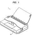
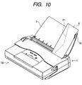
- Fig. 1 is a perspective view showing a condition that a printer is mounted to an ASF according to a first embodiment of the present invention
- Fig. 2 is a view showing a condition that the printer is mounted to the ASF
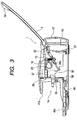
- Fig. 3 is a sectional view of the ASF
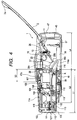
- Fig. 4 is a sectional view of the ASF to which the printer is mounted.
- a printer 101 can be detachably mounted to an ASF 1.
- the ASF 1 and the printer 101 constitutes an image forming apparatus.
- the printer 101 is a so-called compact and portable mobile printer having a battery, and, in the illustrated embodiment, the ASF is not incorporated into the printer 101, and the printer itself can effect only manual sheet insertion.
- the printer 101 itself can be made compact, simpler and cheaper to provide an optimum form as the mobile printer.
- the present invention can be applied to such printer.
- the printer can be used particularly outdoors, in a vehicle or in an office to which the user visited.
- the printer since the number of recording sheets to be required is relatively small, the manual sheet insertion or the incorporated ASF having small capacity can cope with small number of recording sheets.
- the printer 101 is used in the user's office, it may be required that a relatively large number of various kinds of sheets are used.
- the ASF 1 separated from the printer 101 is very useful. That is to say, the ASF 1 is of so-called desk-top type which can always be rested on the desk in the office, and, by mounting the printer 101 to the ASF 1, the printer 101 has a feature of the desk-top printer.
- the ASF 1 has a construction which will be described later, so that various kinds of recording media such as post cards, envelopes, plastic films and cloth can automatically be fed.
- the ASF 1 also acts as a storing container for the printer 101 when the printer is not used as a printer unit itself and is said to have a role of a so-called docking station where the automatic sheet feeding ability is added to the printer.
- the ASF 1 When the printer 101 is not mounted, the ASF 1 according to the present invention can stably be self-contained as the ASF itself, and, further, in a condition that the sheets are contained within the ASF, the printer 101 can be separated from the ASF. With this arrangement, the user can achieve a stand-by condition as the desk-top printer only by mounting the discrete printer 101 to the self-contained ASF 1. This means that the ASF functions as the docking station very convenient for the user.
- the printer 101 When it is desired that the printer 101 is used properly as the mobile printer or as the desk-top printer, it is important that the ASF 1 and the printer 101 can easily be mounted and dismounted relative to each other. The reason is that the user who dismounts the printer 101 from the ASF 1 and transports the separated printer and re-mounts the printer to the ASF every day must expend troublesome effort if the mounting and dismounting of the printer is complicated and time-consumed.
- a mounting opening (referred to as "opening” hereinafter) 1A for mounting the printer 101 is provided in a front surface of the ASF 1.
- a sheet passing path of the printer 101 is substantially horizontal (horizontal path), so that a sheet path which will be described later can be formed by shifting a sheet feeding side of the printer 101 toward the ASF 1 to be inserted into the opening 1A of the ASF 1.
- the printer 101 having the horizontal path is inserted into the ASF 1 substantially in the horizontal direction thereby to mount the printer to the ASF.
- the printer 101 is automatically secured to the ASF 1 (A securing method for securing the printer to the ASF when the printer 101 is mounted to the ASF 1 will be described later).
- the printer 101 is separated from the ASF 1, the securing between the printer 101 and the ASF 1 is released only by pushing a push lever 40 provided on an upper surface of the ASF, so that the printer 101 is pushed out of the front surface of the ASF 1.
- the user can effect the mounting and dismounting between the printer 101 and the ASF 1 so that the printer can be used properly as the mobile printer or as the desk-top printer.
- a bottom surface of the opening 1A is formed on a front part of an ASF base 45 for forming a body of the ASF together with an ASF upper case 47, and there is provided a table portion (recording apparatus supporting portion) 45c for supporting the printer 101 for shifting movement in a mounting direction when the printer 101 is mounted.
- the printer 101 When the printer 101 is mounted to the ASF 1, first of all, the printer 101 is rested on the table portion 45c.
- the user grips upper and lower surfaces of a front (sheet discharging side) central portion of the printer 101 by his one hand so that the printer 101 is slowly rested on the table portion 45c from a rear side (sheet feeding side) thereof (the printer 101 may be gripped by both hands of the user).
- both side surfaces of the printer 101 is directed to positioning bosses (described later) while being guided by printer side guide portions 45a provided on both side ends of the table portion 45c, with the result that the printer is positioned by fitting positioning holes (described later) of the printer 101 onto the positioning bosses.
- the printer 101 it is merely required that the printer 101 be rested on substantially a central portion of the table portion 45c and be pushed rearwardly, but troublesome positioning is not required. As such, when the printer 101 is mounted to the ASF 1, since the printer 101 may be rested on the table portion 45x and then be pushed along the table portion 45c, operability and mounting ability can be improved considerably.
- printer sliding portions 45b on which a rear surface of the printer is slid when the printer 101 is pushed are provided on both ends of the table portion 45c in a direction perpendicular to the printer mounting direction. Further, a stepped portion G1 is defined between the printer sliding portions 45b.
- the printer 101 is provided at its bottom with projections (for example, rubber legs (not shown) for increasing resistance to movement of the printer 101 caused by an external force when the printer itself is used on the desk).
- projections for example, rubber legs (not shown) for increasing resistance to movement of the printer 101 caused by an external force when the printer itself is used on the desk.
- the printer 101 is mounted to the ASF 1, if such rubber legs are contacted with the table portion 45c, a force for pushing the printer 101 into the ASF is greatly increased, thereby worsening the operability.
- the stepped portion G1 formed between the printer sliding portions 45b prevents the contact between the rubber legs and the table portion 45c.
- the stepped portion G1 has a depth greater than lengths of the rubber legs to prevent the contact between the rubber legs and the table portion 45c.
- an eaves portion 47a which forms a part of the opening 1A and disposed substantially in parallel with the table portion 45c is formed on the ASF upper case 47.
- the eaves portion 47a cooperates with the table portion 45c to form a pocket for receiving the printer 101.
- the pocket so formed informs the user of a direction along which the printer 101 is pushed substantially in parallel with the ASF 1 so that the user can push the printer 101 only along this direction.
- This direction coincides with a connecting direction of connectors for electrically connecting the printer 101 and the ASF 1 (described later), so that the connectors can be interconnected during the insertion of the printer 101 into the ASF 1.
- the printer 101 After the printer 101 was mounted, if a front portion (sheet discharging side) of the printer 101 is subjected to an upward force, the eaves portion 47a abuts against the printer 101 to regulate upward movement of the printer 101. Thus, even if the printer 101 is forcibly shifted upwardly with respect to the ASF 1, the upward movement of the printer 101 can be prevented, thereby preventing damage of the mounting portion and dismounting due to the upward movement of the printer 101.
- the eaves portion 47a is greatly protruded at its both sides thereof to form a central recess 47b.
- an operation portion 101B (including a power source switch, for example) provided on the printer 101 can be exposed to outside.
- a clearance between the eaves portion 47a and the upper surface of the printer is selected to about 0.5 mm to 2 mm, the upward movement of the printer can effectively be prevented. If the clearance is too great, the desired effect cannot be achieved.
- the printer 101 By selecting the length L2 of the table portion 45c in the front-and-rear direction to become greater than the half (L1/2) of the length L1 of the printer in the front-and-rear direction in this way, when the printer 101 is mounted to the ASF 1, the printer 101 can be held in a stable condition.
- this relationship may be satisfied at a part of the table portion 45c and is not necessarily satisfied at the entire table portion 45c.
- the length L2 of the table portion 45c in the front-and-rear direction to become smaller than the length L1 of the printer 101 in the front-and-rear direction by a predetermined value or more (15 mm in the illustrated embodiment), when the printer 101 is mounted, a space into which the user's fingers can be inserted can be reserved below the front part of the printer 101.
- the space below the front part of the printer 101 in this way, it can be designed so that the magnitude of the height is not felt great visually. Further, when a thickness (length in the height direction) of the table portion 45c is selected to about 10 mm, the user's fingers can be inserted below the printer 101 in the condition that the ASF 1 is rested on the desk. This is desirable.
- the length L3 of the eaves portion 47a in the front-and-rear direction exceeds 1/2 of the length L1 of the printer 101 in the front-and-rear direction, the pushing amount of the printer during the mounting becomes too great relative to the length of the printer 101 in the front-and-rear direction, and, it was found that operating feeling is lost and that the operation on the upper surface of the printer 101 is obstructed. Further, the great eaves portion 47a makes the entire apparatus bulky visually to give a sense of oppression to the user.
- the length L3 of the eaves portion 47a in the front-and-rear direction is equal to or smaller than 1/2 of the length L1 of the printer 101 in the front-and-rear direction. Further, when the eaves portion 47a is protruded to this extent, the strength of the protruded eaves portion 47a is ensured, thereby giving adequate rigidity to the apparatus.
- the table portion 45c and the eaves portion 47a under the above-mentioned conditions, the operability and the mounting ability are greatly improved, and the pushing direction of the printer 101 can be determined stably, and the flying (upward movement) of the printer can effectively be prevented.
- the opening 1A1 is formed above the printer side guide portions 45a having the height greater than the clearance between the eaves portion 47a and the upper surface of the printer.
- the connectors are exposed and are not connected to each other.
- dirt or foreign matters may enter into the connector portions or great static electricity may be transmitted to internal electric circuit through the connectors to damage the circuit.
- a connector cover for protecting the connector is associated with each connector.
- the connector cover is used as a one-piece part so that, when the printer 101 is mounted to the ASF, the connector cover can be removed.
- the connector cover since the available space is very limited, a cheap removable connector cover not requiring an installation space so much is desirable.
- a printer connector 117 is provided on an upper part of a surface of the printer which is opposed to the ASF 1 when the printer is mounted.
- a sheet feed tray 116 is opened and the printer connector cover 119 is removed from the printer connector 117.
- an ASF connector cover 59 is removed from an ASF connector 44 (described later) shown in Fig. 11.
- the removed connector covers 59, 119 are contained in connector cover containing portions 45d, 45e (Fig. 2) of the table portion 45c.
- the containing portions 45d, 45e utilize the thickness of the table portion 45c and are formed by providing projections having the same sizes as the connector covers in the thickness. While the printer 101 is being mounted to the ASF 1, by containing the connector covers 59, 119 in the connector cover containing portions 45d, 45e, the connector covers 59, 119 can be prevented from being lost.
- the connector cover containing portions 45d, 45e may be formed at any positions on the ASF 1 or the printer 101.
- the connector cover containing portions 45d, 45e may be formed at any positions on the ASF 1 or the printer 101.
- the connector cover containing portions 45d, 45e on the table portion, in the condition that the printer is mounted, since the connector covers are held between the ASF 1 and the printer 101, the connector covers are not dropped or lost, and good appearance can be obtained because the covers are concealed.
- the connector cover containing portions 45d, 45e can be provided for a plurality of connector covers.
- the present invention is applicable.
- Fig. 4 is a sectional view showing the condition that the printer 101 was mounted on the ASF 1.
- a pressure plate 26 for setting a predetermined number of sheets (described later) has one end rotatably supported by a chassis 11 of the ASF and is biased toward a pick-up rubber 23 wound around a pick-up roller 19 in a clockwise direction by means of a pressure plate spring 13 with predetermined pressure.
- the pressure plate 26 When the sheets are set, the pressure plate 26 is displaced away from the pick-up rubber 23 and held there by a cam (described later). In this case, predetermined clearance is maintained between the pick-up rubber 23 and the pressure plate 26, and the sheets are set by inserting the sheets into the clearance.
- leading ends of the sheets abut against a bank sheet (plastic film) 37 provided on a bank 36, thereby positioning the leading ends.
- a most part of each sheet is supported on an ASF sheet feeding tray 2.
- the ASF sheet feeding tray 2 has one end rotatably supported by the ASF upper case 47 and is held at a certain angle when the sheets are supported thereon.
- the pick-up roller 19 starts to rotate in the clockwise direction, and, at the same time, the holding of the pressure plate 26 is released by the cam. As a result, the pressure plate 26 urges the sheets against the pick-up rubber 23. Consequently, the sheets start to be shifted by the surface friction of the pick-up rubber 23. Only one sheet is separated from the other sheets by the bank sheet 37, and the separated sheet is conveyed through an ASF sheet path 58 (Fig. 3) defined by the bank 36 and a positioning base 39.
- the sheet is transferred from an ASF sheet discharge portion 56 (Fig. 3) to a sheet path of the printer through a sheet feeding opening 101A (described later) defined between a platen 105 of the printer and a lower surface of a battery 107 and called as a manual insertion opening (when the printer 101 is used as a single unit).
- a sheet feeding opening 101A (described later) defined between a platen 105 of the printer and a lower surface of a battery 107 and called as a manual insertion opening (when the printer 101 is used as a single unit).
- the printer 101 confirms that the sheet is conveyed from the ASF 1, and the leading end of the sheet abuts against a nip between an LF roller 109 and a pinch roller 110.
- the ASF 1 receives information of the sheet end sensor 108 from the printer 101, the ASF sends a response signal indicating completion of sheet feeding to the printer at a predetermined timing.
- the sheet is being urged against the nip between the LF roller 109 and the pinch roller 110 by resiliency of the sheet with predetermined pressure, thereby effecting registration of the leading end of the sheet (to correct skew-feed).
- the printer 101 which received the response signal indicating completion of sheet feeding from the ASF 1 rotates the LF roller 109 at a predetermined timing to feed out the sheet to a recording portion having a head 115. In this way, predetermined feeding of the sheet is effected, and an image is recorded on the sheet by the head 115. Thereafter, the sheet is conveyed between a sheet discharge roller 112 and a spur roller 111 and is discharged.
- the sheet path (recording medium passing path) R is formed.
- the sheet path R of the printer 101 becomes substantially in parallel with the mounting direction.
- the printer 101 When the sheet is straddled between the ASF 1 and the printer 101 while the sheet is being transferred from the ASF 1 to the printer 101, if the sheet is jammed, it is required that the printer 101 is separated from the ASF 1. In such a case, since the sheet path R is substantially parallel with the connector connecting direction, the printer can be separated from the ASF.
- the sheet path R is perpendicular to the connector connecting direction, when the printer 101 is separated along the connector connecting direction, the sheet must be moved in its thickness direction, with the result that the sheet may be torn and the torn sheet may remains within the apparatus.
- a sheet hard to be torn it may be impossible to separate the printer 101 from the ASF.
- the printer 101 since the sheet path R is substantially parallel with the connector connecting direction, if the sheet is jammed, the printer 101 can be separated by shifting the printer along the sheet surface, with the result that the sheet jam treatment can easily be performed and the sheet is prevented from being torn or remaining within the apparatus.
- the printer 101 is provided with a rotatable sheet feeding tray 116 having one end pivotally supported at a predetermined position.
- the sheet feeding tray 116 serves to stabilize the sheet manual insertion.
- the sheet feeding tray 116 When the sheet feeding tray 116 is opened, the sheet feeding opening 101A is exposed and a reference guide (positioning member) 116a extending vertically from one end of the sheet feeding tray 116 is revealed. When the sheets are inserted, the sheets are inserted along the reference guide 116a.
- the sheet width-wise reference is this reference guide 116a. The sheets are positioned in the width-wise direction by inserting the sheets while abutting one lateral edges of the sheets against the reference guide.
- a similar guide (not shown) provided at the same position with respect to the sheet width-wise direction within the printer cooperates with the reference guide 116a to position the sheets in the width-wise direction.
- An opened condition and a closed condition of the sheet feeding tray 116 are maintained or held by a toggle means (not shown).
- the reference guide 116a provided on the sheet feeding tray 116 Since the longer the guide in a sheet conveying direction the more stable the sheet direction, by using the reference guide 116a provided on the sheet feeding tray 116, the positioning of the sheet in the width-wise direction is stabilized and the skew-feed is prevented. However, even if there is not similar guide within the printer, the sheet can be guided only by the reference guide 116a provided on the movable sheet feeding tray 116.
- the printer 101 when the printer 101 is mounted to the ASF 1, although the reference guide 116a which is the sheet reference for the manually inserted sheet is required to be used for the sheet fed from the ASF 1, it is difficult to convey the sheet automatically fed from the ASF 1 along (while contacting with) the reference guide 116a.
- the sheet reference of the printer 101 and the sheet reference of the ASF 1 must be coincided with each other completely in order that the ASF 1 can perform the same operation (effected by the user) in which the lateral edge of the sheet is contacted with the reference guide 116a while adjusting the sheet by hand.
- the sheet reference of the ASF 1 is an ASF sheet reference 26b provided on the pressure plate 26.
- the sheets can be positioned at the predetermined position.
- great tolerance in construction since it is very difficult to align this position with the reference guide 116a, great cost and a complicated mechanism are required in order to realize such alignment.
- the lateral edge of the sheet interferes with the reference guide 116a to cause the skew-feed of the sheet or damage of the lateral edge of the sheet, or the leading end of the sheet is struck against the reference guide 116a to cause the sheet jam.
- the reference guide 116a is provided only at a position relatively upstream of the manual insertion sheet feeding portion of the printer 101, i.e., as shown in Fig. 5, when the sheet width-wise reference is determined only by the reference guide 116a revealed when the movable sheet feeding tray 116 and there is no member for regulating the width-wise position of the sheet at a downstream side therefrom, as the printer 101 is mounted to the ASF 1, by setting the sheet path R so that the sheet passes above the reference guide 116a, only the sheet positioning performed by the sheet reference 26b of the ASF 1 becomes effective, the interference with the sheet reference of the printer 101 can be avoided.
- the sheet feeding tray 116 of the printer as the single unit in the condition that the sheet feeding tray 116 of the printer as the single unit is opened (i.e., when the manual insertion sheet feeding is effected), the sheet guiding surface of the sheet feeding tray 116 becomes substantially horizontal, but, as shown in Fig. 4, in the condition that the printer 101 was mounted on the ASF 1, by rotating and retarding the movable sheet feeding tray 116 further downwardly from the position (of the sheet feeding tray) when the printer is used as the single unit, the sheet path is more resembled to the sheet path upon the manual insertion.
- the ASF has a reference guide containing portion 36b for containing the sheet feeding tray 116 rotated to the predetermined position.
- the reference guide 116a is guided by a reference guide guiding portion 36c defining the reference guide containing portion 36b to be contained within the reference guide containing portion 36b.
- the sheet feeding tray 116 of the printer has a right end guide (another positioning member) 122 for guiding the other lateral edge of the sheet opposite to the sheet reference.
- the right end guide 122 is slidable with respect to the sheet feeding tray 116 in the sheet width-wise direction so that it can guide the other lateral edge of the sheet opposite to the sheet reference.
- a shape of the right end guide 122 looked at from the sheet thickness direction in the sheet path is substantially the same as that of the reference guide 116a and, when the printer 101 is mounted to the ASF 1, the right end guide 122 contained within the reference guide containing portion 36b, together with the sheet feeding tray 116 and the reference guide 116a.
- the right end guide 122 can be shifted at any position within a predetermined range with respect to the sheet feeding tray 116, when the right end guide 122 is positioned at any position within the predetermined range, the reference guide containing portion 36b can contain the sheet feeding tray 116 having the reference guide 116a and the right end guide 122.
- the printer 101 When the printer 101 is mounted to the ASF 1 in this way, by setting the sheet path at a position spaced apart from the reference guide 116a and the right end guide 122, the sheet reference of the printer can be invalid and only the sheet reference of the ASF can be valid, with the result that the apparatus can be prevented from being made expensive and complicated (since the requirement for alignment between both sheet references can be avoided).
- the fact that the sheet fed from the ASF 1 interferes with the sheet reference 116a and the right end guide 122 of the printer to cause the skew-feed of the sheet and/or the damage of the lateral edge of the sheet and the fact that the sheet is struck against the sheet reference 116a and the right end guide 122 to cause the sheet jam can be prevented.
- the present invention is not limited to such an example, but, for example, the reference guide 116 may be slidable on the sheet feeding tray 116 in the sheet width-wise direction and, as the printer is mounted, the reference guide 116a may be slid in the sheet width-wise direction by a shifting means (such as a cam) synchronous with the mounting of the printer so that the sheet can pass alongside the reference guide 116a.
- a shifting means such as a cam
- the reference guide is provided at the same position as the reference guide 116a with respect to the sheet width-wise direction within the printer to increase a length for guiding the sheet thereby to stabilize the positioning of the sheet, it is difficult to dispose the sheet path at a position spaced apart from all of the reference guides.
- the sheet reference guide 116a of the printer and the sheet reference 26b of the ASF are previously arranged at offset positions. That is to say, the sheet reference 26b of the ASF is set at a position deviated inwardly from the sheet reference guide 116a of the printer (i.e., the recording position of the head 115 perpendicular to the sheet conveying direction) by a distance t so that, when the sheet is fed from the ASF 1, the sheet does not interfere with the sheet reference guide 116a of the printer.
- the deviation amount t between the sheet references is greater than the positioning tolerance between the printer 101 and the ASF 1 in the sheet width-wise direction and is determined in consideration of the possibility that the sheet may be skew-fed from the ASF 1.
- the deviation amount t between the sheet references is selected to about 0.6 mm.
- the recording position when the recording is effected by the printer alone is deviated from that when the recording is effected by the printer mounted on the ASF by the same amount as the deviation amount t.
- the printer 101 since the printer 101 is electrically connected to the ASF 1 via the connectors 44, 117, the printer 101 can electrically detect the mounting/non-mounting of the ASF 1, and the judgment for deviating the recording position (position of the head 115) can be effected on the basis of a detected result. Incidentally, this judgment may be effected by additional ASF detecting switch, as well as the aforementioned electrical connection.
- the interference between the reference guides can be avoided, and, thus, the image can be recorded at the same positions on the sheets in both cases. Accordingly, inconvenience (for example, recording at different positions on the sheets in both cases) caused because of the deviation between the recording positions in both cases can be eliminated.
- the deviation amount between the sheet references is completely the same as the deviation amount between the recording positions, but, these deviation amounts may be differentiated within an allowable range.
- the ASF sheet feeding tray 2 has one end rotatably supported by the ASF upper case 47 so that the ASF sheet feeding tray 2 can be folded around the supported position.
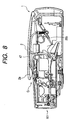
- the ASF sheet feeding tray 2 is opened at a certain predetermined angle; whereas, when the sheets are not stacked, the tray can be closed or folded as shown in Fig. 8.
- the ASF 1 according to the illustrated embodiment not only serves to use the portable printer 101 as the desk-top printer but also serves to provide the portable ability of the ASF 1 to which the printer 101 is mounted (because of compactness).
- the ASF sheet feeding tray 2 In order to realize such use condition, when the ASF sheet feeding tray 2 is closed, it must be closed along the profile of the ASF 1 (to which the printer is mounted) as much as possible. To this end, the ASF sheet feeding tray 2 is formed from a thin plate.
- any part of the tray is engaged by the ASF upper case 47 via an engagement means (not shown) such as a hook to prevent inadvertent opening of the sheet feeding tray during the transportation.
- the engagement means for the sheet feeding tray 2 may be provided on the printer or on the ASF itself, but, more preferably, such engagement means is provided on a side guide portion 2a which will be described later. When the engagement means provided on the printer is used, such engagement means can also act as an engagement maintaining means (which may be "complete lock").
- an ASF sheet feeding tray side guide portion (referred to as "side guide portion” hereinafter) 2a as a regulating member is provided at an upstream part of the ASF sheet feeding tray 2.
- side guide portion 2a By providing such a side guide portion 2a, after the envelope E is set in the ASF 1 longitudinally, when the envelope is fed, even if the envelope is subjected to a force tending to rotate the envelope in the clockwise direction, a rear lateral edge of the envelope abuts against the side guide portion 2a, thereby regulating the clockwise rotation.
- the tab E1 When the envelope is fed in the longitudinal direction, particularly at a timing for starting the feeding of the envelope E, the tab E1 is subjected to the resistance. In the illustrated embodiment, this occurs when the envelope E rides over the bank sheet 37 and when a leading end of the envelope is lifted along the inclined surface of the bank 36. When this timing is passed, the influence of the resistance of the tab E1 is decreased, with the result that the rotation of the envelope E is not generated even absence of the side guide portion 2a.
- the side guide portion 2a is provided on a part of the ASF sheet feeding tray 2 in the vicinity of the trailing end of the envelope to prevent the rotation of the envelope. There is no side guide along the entire lateral edge of the envelope.
- a stepped portion or gap G is created between the ASF upper case 47 and the upper surface of the printer, and, when the ASF sheet feeding tray 2 is closed, the side guide portion 2a is housed within the gap G as shown in Fig. 8.
- the side guide portion 2a on the part of the ASF sheet feeding tray 2 and by housing the side guide portion 2a within the gap G, when the ASF sheet feeding tray 2 is closed, the side guide portion 2a does not interfere with other parts so that the ASF sheet feeding tray 2 can be closed along the outer profile of the ASF, thereby keeping the portable ability and made the apparatus more compact.
- a height of the side guide portion 2a is greater than a thickness of the sheet stack such as envelope stack, and, to achieve the above effect, a depth of the gap G is required to be greater than the height of the side guide portion 2a.
- the rotation preventing effect during the envelope longitudinal feeding can be obtained, other than the envelope, when other sheets having a length similar to that of the envelope are fed, if rotation is generated for any reason, such rotation can be regulated (prevented).
- the side guide portion 2a is integrally formed with the ASF sheet feeding tray 2, the manufacturing cost is cheap.
- a recess may be previously formed in the printer 101 or in the ASF 1 and the side guide portion 2a may be housed in such a recess.
- Fig. 11 is a perspective view showing arrangement of parts associated with the printer mounting/dismounting mechanism of the ASF
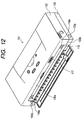
- Fig. 12 is a view showing arrangement of parts associated with the mounting/dismounting of the printer 101 with respect to the ASF 1.
- a positioning base 39 is a member for positioning the sheet path between the ASF 1 and the printer and positioning the connection between the ASF connector 44 of the ASF 1 and the printer connector 117.
- Two positioning bosses (first and second pins) 39d, 39e are provided on the positioning base 39.
- the first positioning boss 39d is fitted into a first positioning hole (circular hole) 118a provided in a substrate holder 118 of the printer 101 as shown in Fig. 12, and the second positioning boss 39e is fitted into a second positioning hole (elongated hole) 118b.
- the first and second positioning bosses 39d, 39e and the first and second positioning holes 118a, 118b engaged by such first and second positioning bosses 39d, 39e constitute a positioning means.
- connection between the connectors is effected after the positioning effected by fitting between the positioning bosses 39d, 39e and the positioning holes 118a, 118b, the damage of the connectors due to positional deviation between the connectors can be prevented. Further, the positioning between the ASF 1 and the printer 101 in an x and z directions is effected by the fitting of the bosses 39d, 39e, the positioning of the sheet path between the printer 101 and the ASF 1 is achieved simultaneously.
- retractable hooks 16 (left) and 17 (right) are provided on the printer sliding portions 45b of the ASF 1.
- hook fixing holes 103y, 103z into which the two hooks 16, 17 are to be fitted are formed in both side portions of the base 103 of the printer 101.
- the left and right hooks 16, 17 of the ASF 1 are fitted into the hook fixing holes 103y, 103z of the printer 101, thereby effecting the positioning of the printer 101 in the y direction.
- the push lever 40 When the user dismounts the printer 101 from the ASF 1, the push lever 40 is depressed in the direction shown by the arrow 40A. That is to say, when the push lever 40 is depressed, the left and right hooks 16, 17 protruded from the printer sliding portions 45b are retarded toward a direction shown by the arrow 40A to be disengaged from the hook fixing holes 103y, 103z of the printer 101.
- a sheet feeding side upper part 102a of the printer 101 is pushed in a direction shown by the arrow 43A (y direction) by pop-ups 43a, 43b provided on the ASF 1, the connection between the connectors 44, 117 is released.
- the pop-ups 43a, 43b are biased toward the direction 43A (y direction) by elastic members (not shown), and they can be slid in the y direction.
- the biasing force of the pop-ups 43a, 43b acts as a reaction force when the printer 101 is mounted to the ASF 1, if the biasing force is too great, the printer 101 cannot be inserted into the ASF 1, thereby causing poor mounting.
- the biasing force is selected to an appropriate value (for example, to an extent that when, the printer 101 is mounted to the ASF 1, the ASF is not moved by the biasing force).
- Fig. 13 shows arrangement of parts associated with the mounting of the printer to the ASF 1.
- the push lever 40 is rotatably (in directions 40A, 40B and 40C) attached to a lever shaft 42 secured to the positioning base 39.
- the push lever 40 and the chassis 11 of the ASF 1 are interconnected by a push lever spring 7.
- the push lever 40 is provided with a rotation preventing boss 40c and the positioning base 39 is provided with slide surfaces 39a, 39b, 39c against which the boss 40c abuts (for clarify's sake, the slide surface 39c is shown by the two dot and chain line).
- the left and right hooks 16, 17 are secured to a hook shaft 18 rotatably attached to the chassis 11 so that the left and right hooks 16, 17 are operated in a synchronous manner.
- a connecting spring 9 is disposed between the left hook 16 and the push lever 40 so that a lower end 40d of the push lever 40 always abuts against an upper surface of the left hook 16 by the connecting spring 9.
- a hook spring 3 is disposed between the left hook 16 and the ASF base so that a pawl portion 16a of the left hook 16 is maintained in a protruded condition (from the printer sliding portion 45b of the ASF base 45) by the hook spring 3.
- Fig. 14 shows a condition that the printer 101 is rested on the printer sliding portion 45b for preparing for the mounting of the printer 101 to the ASF 1.
- the printer 101 is shown by the two dot and chain line. Further, the base of the printer 101 is shown as a sectional view.
- the printer 101 As the printer 101 is shifted in the direction shown by the arrow A along the printer sliding portion 45b of the ASF base 45 to push the printer into the ASF 1, firstly, the pawl portion 16a of the left hook 16 abuts against a base leading end 103w of the printer 101.
- the left hook 16 is rotated downwardly around the hook shaft 18 in a direction shown by the arrow 16A until an upper end 16a2 of the pawl portion 16a abuts against a bottom surface 103x of the base 103.
- the push lever 40 is lowered in the direction 40A since it is operated in synchronous with the left hook 16 due to the presence of the connecting spring 9.
- the positioning bosses 39d, 39e are already fitted into the positioning hole 118a (Fig. 12) and the positioning elongated hole 118b (Fig. 12) of the printer 101, so that the positioning between the connectors is completed before the ASF connector 44 (Fig. 13) is connected to the printer connector 117 (Fig. 12).
- the ASF connector 44 is connected to the printer connector 117.
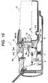
- the pawl portion 16a of the left hook 16 reaches the hook fixing hole 103y of the printer 101, as shown in Fig. 16, the left hook 16 is lifted in a direction shown by the arrow 16B by the biasing force of the hook spring 3, with the result that the pawl portion 16a of the left hook 16 abuts against a wall of the hook fixing hole 103y of the printer 101, thereby fitting the pawl portion into the hook fixing hole.
- the push lever 40 is lifted in the direction 40B.
- the user can confirms the fact that the printer 101 is mounted (secured) to the ASF 1.
- the push lever 40 Since the left and right hooks 16, 17 are secured to the hook shaft 18, so long as both the left and right hooks 16, 17 are not entered into the hook fixing holes 103y, 103z (Fig. 12), the push lever 40 is not lifted in the direction 40B. Accordingly, poor mounting in which, for example, the printer 101 is mounted to the ASF 1 obliquely so that one of the hooks is not fitted into the corresponding hook fixing hole can be prevented by confirming the height position of the push lever 40 by the user.
- the fitting positions between the hooks 16, 17 and the printer 101 is set to be the same or slightly higher than the rotational center positions of the hooks 16, 17.
- the printer 101 is forcibly separated from the ASF 1, since the hooks 16, 17 remain in a force balancing position, i.e., a position having the same height as the rotational center positions of the hooks 16, 17, the printer 101 is not dislodged from the ASF 1.
- the user When the user wants to dismount the printer 101 from the ASF 1, as shown in Fig. 16, the user pushes a push portion 40a of the push lever 40 in the direction 40A by his finger. In this case, since the boss 40c is pinched between the guide surfaces 39a, 39b of the positioning base 39, the push lever 40 cannot rotate around the lever shaft until the guide surface 39b is retarded. Thus, the push lever is lowered in the direction 40A.
- the push lever 40 Since the push lever 40 is operated in synchronous with the left hook 16, at the same time when the push lever 40 is lowered, the left hook 16 is rotated around the hook shaft 18 in the direction 16A, with the result that pawl portion 16a of the left hook 16 is disengaged from the hook fixing hole 103y of the printer 101, as shown in Fig. 17. Although not shown, at the same time, the right hook 17 is disengaged from the hook fixing hole 103z.
- the pushing-out mechanism is added.
- Fig. 17 shows a condition that the printer 101 is not moved even when the hook 16 is disengaged from the printer 101.
- the left hook 16 has already disengaged from the hook fixing hole 103y and the regulation of the guide surface 39b of the positioning base 39 for regulating the movement of the boss 40c of the push lever 40 has already released.
- the push lever 40 is positioned so that the lever shaft 42 is urged against the upper end surface of a sliding hole 40e to regulate the depression of the left hook 16. Further, since a surface 40d of the push lever which abuts against the left hook 16 is curved (arc a center of which is the lever shaft 42), even when the push lever 40 is rotated, the position of the left hook 16 is not changed.
- a pushed amount of the printer 101 (pushed by the push lever 40) is selected to be a shifting amount by which the fitting between the left hook 16 and the printer 101 is released and the connection between the connectors is released.
- the left hook 16 is lifted in the direction 16B by the hook spring 3.
- the push lever 40 is pushed upwardly by the left hook 16, with the result that the boss 40c of the push lever 40 abuts against the guide surface 39c of the positioning base 39. Thereafter, the push lever 40 is rotated in the direction 40B by the force of the spring 7.
- the connection between the connectors is ultimately released, and the left hook 16 is disengaged from the printer 101.
- the user can easily dismount the printer 101 from the ASF 1.
- the printer 101 when the printer 101 is dismounted from the ASF 1, since the push lever 40 is pushed substantially in the vertical direction, a vertical force acts on the ASF 1 itself. Thus, when the printer 101 is pushed substantially in the horizontal direction, the ASF 1 is not moved. Further, since the printer 101 is pushed substantially in the horizontal direction, poor dismounting (which may occur if the printer 101 is moved in the mounting direction again by its own weight) can be prevented.
- Fig. 19 shows arrangement of and a force relationship between the push lever 40, pop-ups 43a, 43b, positioning bosses 39d, 39e, left and right hooks 16, 17 and ASF connector 44 in the illustrated embodiment.
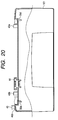
- Fig. 20 is a sectional view of the upper part of the ASF 1.
- the left and right hooks 16, 17 and the positioning bosses 39d, 39e of the printer 101 are provided on both width-wise end portions of the printer 101.
- the ASF connector 44 is disposed between the two positioning bosses 39e, 39d near the second positioning boss 39e.
- the push lever 40 and the second pop-up 43b are disposed more remotely than the ASF connector 44 with respect to the first positioning boss 39d.
- the pop-ups 43a, 43b are auxiliary members for reducing the user's force required for pushing the push lever 40 and are slidably biased by elastic members (not shown) toward the printer pushing direction.
- the printer 101 is pushed while sliding it on the printer sliding portions 45b and rotating around the positioning boss 39d or 39e.
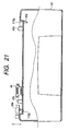
- the printer positioning hole 118a associated with the first positioning boss is the circular hole and the printer positioning hole 118b associated with the second positioning boss is the elongated hole (refer to Fig. 12), from the condition shown in Fig. 20, when the printer 101 tries to be dismounted from the ASF 1 while rotating around the first positioning boss 39d, a positional relationship between the printer 101 and the ASF 1 becomes as shown in Fig. 21.
- the non-detachment is prevented by deviating the fitting position between the first positioning boss 39d and the positioning hole 118a (rotational center of the printer) toward the connector disconnecting direction by the force of the first pop-up 43a before the printer 101 is pushed out by the push lever 40 and the second pop-up 43b.
- a force required for pushing out the printer 101 by the pushing force of the first pop-up 43a while rotating the printer around the second positioning boss 39e has the following value: F1 > (X1/X2) ⁇ P1 + P2 where, F1 is the printer pushing force of the first pop-up 43a, P1 is the disconnecting force for disconnecting the connector 44, P2 is a friction force between the printer 101 and the printer sliding surfaces 45b of the ASF 1, X1 is a distance between the second positioning boss 39e (rotational center) and the connector 44, and X2 is a distance between the second positioning boss 39e (rotational center) and the first pop-up 43a.
- the printer pushing force F1 of the first pop-up 43a acts as the reaction force when the printer 101 is mounted to the ASF 1, and, in consideration of the fact that the connector disconnecting force is generally 1 to 2 kgf, the value of X1/X2 is preferably equal to or smaller than 0.5.
- the pawl height of the right hook 17 is selected to be smaller than the pawl height of the left hook 16 so that the right hook 17 is disengaged from the hook fixing hole 103z (Fig. 12) before the left hook 16 is disengaged from the hook fixing hole 103y.
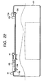
- the printer 101 is rotated around the second positioning boss 39e (rotational center) by the pushing force of the first pop-up 43a, with the result that the fitting position between the first positioning boss 39d and the positioning hole 118a is shifted toward the connector disconnecting direction, as shown in Fig. 22.
- the left hook 16 is disengaged from the hook fixing hole 103y.
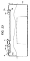
- the printer 101 when the printer 101 is pushed out by the push lever 40 and the second pop-up 43b, as shown in Fig. 23, the printer 101 can be dismounted from the ASF 1 without non-detachment between the first positioning boss 39d and the positioning hole 118a.
- the push lever 40 and the second pop-up 43b are arranged between the first positioning boss 39d (rotational center for the printer 101) and the ASF connector 44, if the connecting force between the connectors is great, the printer 101 will be rotated around the connector 44, with the result that the non-detachment between the first positioning boss 39d and the positioning hole 118a (circular hole) of the printer 101 occurs, thereby deforming or damaging the boss 39d.
- only the first pop-up 43a may be provided.
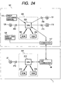
- Fig. 24 is a connection block diagram of a printer control portion and an ASF control portion according to the present invention.
- a printer control portion 202 for controlling the printer 101 is disposed on a substrate 123 shown in Fig. 4 and includes a microcomputer in which a CPU 203, a ROM 204 and a RAM 205 are connected by buses.
- the printer control portion 202 drives a carriage motor 121 via a motor driver 208 and drives the recording head 115 mounted on a carriage (not shown) connected to the carriage motor 121 via a head driver 210 on the basis of printer control program stored in the ROM 204, thereby effecting one-line recording.
- the printer control portion 202 drives a sheet feeding motor 120 via a motor driver 206 to feed the sheet and drives the carriage motor 121 and the recording head 115 again, thereby effecting next one-line recording. By repeating these operations, the recording on the sheet is completed.
- the connector 117 acts as a bi-communication port for outputting a command signal from the CPU 203 of the printer control portion to an external part and inputting an external response signal to the CPU 203 and can supply an electric power to the external part as will be described later.
- a sheet end sensor 108 is provided within the printer 101 and has an optical or mechanical switch. Output voltage of the sheet end sensor 108 is changed from a LOW condition to a HIGH condition.
- a sheet discharge sensor 113 has the same function as the sheet end sensor 108, and output voltage of this sensor 113 is changed to a HIGH condition if the recorded sheet remains within the printer 101.
- the output voltage values of the sheet end sensor 108 and the sheet discharge sensor 113 can be monitored by the CPU 203, and the output voltage of the sheet end sensor 108 can be outputted to outside directly through the connector 117.
- an ASF control portion 201 for controlling the ASF 1 includes a microcomputer in which a CPU 213, a ROM 214 and a RAM 215 are connected by buses.
- the CPU 213 drives a sheet feeding motor 27 via a motor driver 216 on the basis of ASF control program stored in the ROM 214.
- the ASF connector 44 acts as a bi-communication port for receiving a signal from an external equipment such as the printer 101 and for outputting a signal from the CPU 213 of the ASF control portion 201.
- Fig. 26 schematically shows the detailed constructions of the connector 117 and the ASF connector 44.
- the connector 117 and the ASF connector 44 have eight ports 117a to 117h and 44a to 44h, and, when the ASF 1 is mounted to the printer 101, the corresponding ports are interconnected electrically.
- the ASF 1 includes a GND line 44a, a 5V power source line 44b for a signal, a 24V power source line 44e for driving the sheet feeding motor 27, a transmitting port 44f for transmitting a signal to the printer, a receiving port 44g for receiving a signal from the printer, and a line 44h for receiving the output voltage of the sheet end sensor 108 of the printer 101. Since the ports 44c and 44d become short-circuit, in the printer 101, it can easily be ascertained that the equipment is connected to the external part via the ports 117c and 117d.
- Fig. 25 is a sectional view showing the condition that the ASF (to be mounted) according to the present invention is mounted to the printer.
- the sheet feeding roller 19 for feeding out the sheet 200 is provided with the sheet feeding rubber 23 mounted thereon. When the sheet feeding roller 19 is rotated, the sheet 200 is conveyed by the frictional force of the sheet feeding rubber 23.
- the pressure plate 26 on which the sheets 200 are stacked has both ends (upstream in the sheet conveying direction) rotatably supported by the ASF chassis 11.
- the pressure plate 26 is biased toward the sheet feeding rubber 23 by the pressure plate spring 13.
- cam portions 19c provided on both ends of the sheet feeding roller 19 are engaged by cam portions 26a provided on both ends of the pressure plate 26, the pressure plate 26 is spaced apart from the sheet feeding rubber 23 so that the sheets 200 can be set smoothly.
- the bank 36 has an abutment surface 36a disposed on an extension line of the pressure plate 26 in the sheet conveying direction. When the sheets 200 are set, the leading ends of the sheets are urged against the abutment surface 36a.
- the bank sheet (sheet separating member) 37 is attached to the abutment surface 36a.
- the bank sheet 37 is formed from an elastic member such as plastic film, so that the sheets 200 are separated one by one by an elastic force generated when the bank sheet is flexed.
- the LF roller 109 for conveying the sheet 200 is constituted by coating material having high coefficient of friction such as urethane resin on a surface of a metallic pipe and is rotated by the sheet feeding motor 120 shown in Fig. 24 and cooperates with the pinch roller 110 to pinch the sheet 200 therebetween and convey the sheet.
- the recording head 115 serves to record image information on the conveyed sheet 200 and is mounted on the carriage (not shown) reciprocating in the longitudinal direction of the LF roller 109.
- the recording head 115 is driven by the carriage motor 121 (Fig. 24) together with the carriage to be reciprocated in the width-wise direction of the sheet 200 (perpendicular to the plane of Fig. 25).
- the spur rollers 111 and the sheet discharge rollers 112 are disposed at a downstream side of the LF roller 109 and the recording head 115 and constitutes two pairs of rollers for conveying the recorded sheet 200.
- the discharge rollers 112 are connected to the LF roller 109 via drive transmitting members (not shown) and are rotated by the LF roller 109 in the same direction as the LF roller 109 to convey the sheet 200.
- the sheet end sensor 108 is disposed at an upstream side of the LF roller 109 in the sheet path, and a sheet discharge sensor is disposed between two pairs of sheet discharge rollers. Output voltage of each of these sensors is changed from a LOW condition to a HIGH condition when the sheet 200 passes through the sensor.
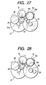
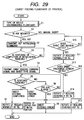
- Figs. 27 and 28 show a drive mechanism of the ASF (to be mounted) according to the present invention.
- the sheet feeding motor 27 is a reversible stepping motor.
- An idle gear 28 is meshed with a motor gear 27a of the sheet feeding motor 27.
- An ASF double gear 29 including two gears having different diameters is meshed with the idle gear 28.
- a normal rotation planetary gear 31 is meshed with the small diameter gear of the ASF double gear and is revolved around the ASF double gear.
- a reverse rotation sun gear 33 including two gears having different diameters is meshed with the small diameter gear of the ASF double gear.
- a reverse rotation planetary gear 35 is meshed with the small diameter gear of the reverse rotation sun gear 33 and is revolved around the reverse rotation sun gear.
- a sheet feeding roller gear 19a provided on an end of a shaft of the sheet feeding roller 19 has a non-toothed portion 19b. The sheet feeding roller gear 19a is disposed on revolution paths of the normal rotation planetary gear 31 and the reverse rotation planetary gear 35 and is adapted to be engaged by these gears.
- Fig. 28 when the sheet feeding motor 27 is rotated (normal rotation) in a direction shown by the arrow f, the gears are rotated in directions shown by the respective arrows. That is to say, the normal rotation planetary gear 31 is revolved (in the direction shown by the arrow) around the ASF double gear 29 via the idle gear 28 and the ASF double gear 29 from a position shown by the broken line in Fig. 28 toward a position shown by the solid line to be engaged by the sheet feeding roller gear 19a. As a result, the sheet feeding roller 19 is rotated in the direction shown by the arrow in Fig. 28 (direction along which the sheets 200 rested on the pressure plate 26 are fed out toward the printer 101).
- the sheet feeding roller 19 is rotated only in the direction along which the sheet 200 is fed out toward the printer 101 and is not rotated in the opposite direction.
- the printer 101 When recording command is received from an external information equipment such as a computer, the printer 101 performs the sheet feeding operation and then performs the recording operation.
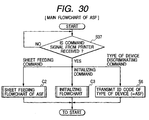
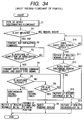
- Fig. 29 is a control flowchart showing the sheet feeding operation of the printer 101.
- the printer control portion 202 of the printer 101 executes a sub flowchart C1.
- the sub flowchart C1 serves to discriminate a kind of the apparatus mounted on the printer thorough the ports 117f, 117g shown in Fig. 26.
- step S1 the program goes to a step S1 where, if the result of the sub flowchart C1 indicates the fact that the ASF is mounted on the printer 101, since the sheet is fed from the ASF, the program goes to a step S2.
- the printer control portion 202 transmits an initializing command signal to the ASF, and then the program goes to a step S3.
- step S3 if there is no response signal indicating completion of initialization from the ASF, the program returns to the step S3.
- the program goes to a step S4.
- the printer control portion 202 transmits a sheet feeding command signal and a sheet type signal indicating type of sheet to be fed (ordinary paper, coated paper, post card, glossy film or the like) to the ASF, and the program goes to a step S5.
- step S5 if there is no response signal from the ASF, the program goes to a step S8 where, if a predetermined limit time period t2 is not elapsed, the program returns to the step S5.
- step S8 if the limit time period t2 from the start of the sheet feeding is elapsed, the program goes to a step S9 where the printer control portion 202 emits sheet feeding error signal, and the sheet feeding operation is ended.
- the step S5 if there is response from the ASF and the response is a signal indicating sheet feeding completion, the program goes to a step S7.
- the step S7 serves to effect feeding of a leading end of the sheet 200 to the initial position.
- the printer control portion 202 drives the sheet feeding motor 120 to rotate the LF roller 109 by a predetermined amount R3 in the sheet conveying direction (normal direction), and the sheet feeding operation is ended.
- the predetermined amount R3 is selected so that the leading end of the sheet 200 does not reach a sheet detectable area of the sheet discharge sensor 113 but reach immediately below the recording head 115. Accordingly, when the printer 101 then starts to effect the recording on the sheet 200, it is not required that the sheet 200 is returned toward the upstream side in the conveying direction. Thus, since the trailing end of the sheet does not strike against the internal mechanisms of the ASF, folding of the sheet and erroneous feeding of the sheet can be prevented.
- step S5 if there is response from the ASF and the response is a signal indicating sheet feeding error, the program goes to a step S9, where the printer control portion 202 emits the sheet feeding error signal, and the sheet feeding operation is ended.
- step S1 if the result of the sub flowchart C1 indicates the fact that the ASF is not mounted on the printer 101, since the sheet is manually fed (manual insertion), the program goes to a step S10.
- step S10 if the sheet is not inserted by the user, since the output voltage of the sheet end sensor 108 is in the LOW condition, the sheet is not detected, and the program returns to the step S10.
- the program goes to a step S11.
- the printer control portion 202 drives the sheet feeding motor 120 via the motor driver 206 to rotate the LF roller 109 by a predetermined amount R4 in the normal direction (direction along which the sheet is conveyed during the recording).
- the predetermined amount R4 is selected so that the leading end of the sheet 200 can reach the sheet detectable area of the sheet discharge sensor 113. Then, the program goes to a step S12, where, if the sheet discharge sensor 113 detect the sheet 200, it is judged that the sheet feeding is succeeded, and the program goes to a step S13.
- the printer control portion 202 drives the sheet feeding motor 120 via the motor driver 206 to rotate the LF roller 109 by a predetermined amount R5 in the reverse direction (direction opposite to the direction along which the sheet is conveyed during the recording).
- the predetermined amount R5 is selected so that the sheet 200 conveyed to the sheet detectable area of the sheet discharge sensor 113 is returned up to the recording start position but the leading end of the sheet 200 does not leave the nip between the LF roller 109 and the pinch roller 110.
- the printer control portion 202 drives the sheet feeding motor 120 via the motor driver 206 to rotate the LF roller 109 by a predetermined amount R6 in the reverse direction.
- the predetermined amount R6 is selected to a value sufficient to leave the sheet 200 conveyed to the sheet detectable area of the sheet discharge sensor 113 from the nip between the LF roller 109 and the pinch roller 110.
- the manual insertion by ascertaining whether the sheet is detected by the sheet discharge sensor 113 or not, the success of the sheet feeding can surely be confirmed, and, if the sheet feeding is failed, since the sheet 200 is returned up to the position where the sheet is not pinched between the LF roller 109 and the pinch roller 110, the sheet 200 can easily be removed, and the manual insertion is effected again.
- the printer 101 After the sheet feeding operation is finished by the above-mentioned sheet feeding control flowchart, the printer 101 performs the recording operation.
- the printer control portion 202 drives the carriage motor via the motor driver 298 and drives the recording head 115 mounted on the carriage (not shown) connected to the carriage motor 121 via the head driver 210, thereby effecting one-line recording.
- the printer control portion 202 drives the sheet feeding motor 120 via the motor driver 206 to convey the sheet 200 by an amount corresponding to one line and drives the carriage motor 121 and the recording head 115 again, thereby effecting next one-line recording.
- the printer control portion 202 drives the sheet feeding motor 120 to rotate the LF roller 109 in the normal direction.
- the sheet discharge rollers 112 are rotated to discharge the sheet 200 out of the printer 101.
- Fig. 30 shows a main control flowchart of the ASF which can be mounted to the printer according to the present invention.
- the ASF control portion 201 according to the present invention is normally in a waiting condition after it was connected to the printer 101, and, as shown in a step S37, if a command signal from the printer 101 is not received, the step S37 is repeatedly executed until the command signal is received.
- the command signal from the printer 101 is received through the serial receiving port 44g shown in Fig. 26, in accordance with the contents of the command signal, the program goes to the following sub flowchart or the following step.
- the program goes to a sub flowchart C2 for controlling the sheet feeding operation of the ASF; whereas, when the command signal indicates "initializing command”, the program goes to a sub flowchart C3 for controlling the initializing operation. After the respective sub flowcharts are completed, the program goes to the step S37 again to restore the waiting condition.
- the command signal from the printer 101 indicates "type of device discriminating command”
- the program goes to a step S6.
- code ID indicating the type of the ASF 1 itself is transmitted to the printer 101 through the serial transmitting port 44f, the program goes to the step S37 again to restore the waiting condition.
- Fig. 31 shows the sub flowchart C2 for controlling the sheet feeding operation of the ASF 1.
- the program goes to a step S15, where a drive table T for the sheet feeding motor 27 optimum to the type of the sheet to be fed is read-in from the ROM 214 to the CPU 213 on the basis of the sheet type information received from the printer 101 together with the sheet feeding command signal.
- the drive table T includes information regarding a driving speed of the sheet feeding motor (pulse motor) 27 and registration pulse number P5 for rotating the sheet feeding roller 19 by an optimum amount depending upon the type of the sheet during the registration operation in a step S22 which will be described later.
- a several number of tables are prepared in consideration of possible sheet properties.
- the program in the ASF control portion 201 goes to a step S16, where "0" is set as initial values of variables defined by INIT, n, Pc.
- the variables are stored in the RAM 215.
- the INIT is a graph showing whether the phase of the sheet feeding roller 19 in the rotational direction is in an initial position or not, n is a rotation number counter indicating the number of rotations of the sheet feeding roller 19 after the sheet feeding flowchart C2 is started, and Pc is a pulse number counter indicating the number of pulses by which the sheet feeding motor 27 is rotated in the reverse direction.
- step S17 the ASF control portion 201 drives the sheet feeding roller 19 by one pulse in the reverse direction via the sheet feeding motor driver 216.
- step S18 the value of the pulse number counter is increased by 1, then the program goes to a step S19.
- step S19 the ASF control portion 201 compares the value of the pulse number counter with allowable pulse number Pmax.
- the allowable pulse number Pmax is a total number of pulses from when the sheet feeding motor 27 starts to rotate in the reverse direction to when the sheet feeding roller is rotated to the position where the non-toothed portion 19b of the sheet feeding roller gear is opposed to the reverse rotation planetary gear 35 (Fig. 27) to prevent the further rotation.
- the program goes to a step S20.
- the ASF control portion 201 ascertains the output voltage of the sheet end sensor 108 within the printer 101 via the port 44h (Fig.
- the program goes from the step S19 to a step S24.
- the ASF control portion 201 drives the sheet feeding motor 27 by a predetermined pulse number P4 in the normal direction.
- the predetermined pulse number P4 is selected to a value sufficient to rotate the sheet feeding roller 19 to the initial position by the normal rotation planetary gear 31. That is to say, by executing the step S24, the sheet feeding roller 19 is rotated up to the phase which is a position obtained after just one revolution of the roller from the initial position.
- step S25 the value of the pulse number counter Pc is returned to "0" and the value of the rotation number counter n is increased by one, and the program goes to a step S26.
- the ASF control portion 201 executes the steps S17 to S20 repeatedly, with the result that the sheet feeding roller 19 starts to the second rotation to further convey the sheet 200.
- the output voltage of the sheet end sensor 108 is changed to the HIGH condition, and the program goes from the step S20 to a step S21.
- the ASF control portion 201 compares a value obtained adding the read-in registration pulse number P5 in the drive table T to the value of the pulse number counter Pc with the magnitude of the allowable pulse number Pmax. If Pc + P5 ⁇ Pmax, since the transmission of the reverse drive is not interrupted on the way even when the sheet feeding motor 27 is further rotated by P5 pulses in the reverse direction, the program goes to a step S22.
- step S24 the sheet feeding motor is rotated by P4 pulses in the normal direction again to return the sheet feeding roller 19 to the initial position. Then, in a step S25, 0 is inserted into the counter Pc and n + 1 is inserted into the counter n, and the program goes to a step S26.
- the step S22 serves to effect the registration.
- the ASF control portion 201 drives the sheet feeding motor 27 in the reverse direction by the pulse number P5 in the read-in drive table T to rotate the sheet feeding roller 19.
- the leading end of the sheet 200 is further fed into the interior of the printer 101 from the position where the leading end is detected by the sheet end sensor 108 and is stopped by abutting against the nip between the LF roller 109 and the pinch roller 110 which are now stopped.
- the trailing end of the sheet 200 is further pushed by the sheet feeding roller 19.
- the tip end of the sheet 200 is aligned with the nip between the LF roller 109 and the pinch roller 110.
- the program goes to a step S23, where the ASF control portion 201 transmits a signal indicating completion of the sheet feeding to the printer 101 via the serial transmitting port 44f, and the operation is ended.
- the ASF control portion 201 executes a loop comprised of the steps S17 ⁇ S18 ⁇ S19 ⁇ S20 ⁇ S17 repeatedly by several times, and then, after the operation in which the program is returned to the step S17 through the steps S19 ⁇ S24 ⁇ S25 ⁇ S26 is repeated by two times, at the third time, when the program reaches the step S26, since the rotation number counter n for the sheet feeding roller 19 becomes "3", the program goes to a step S27, where the sheet feeding error signal is transmitted to the printer 101, and the operation is ended.
- Fig. 32 shows a sub flowchart C3 for controlling the initializing operation of the ASF 1.
- the predetermined pulse number P0 is selected to a value sufficient to rotate the non-toothed portion 19b to the position where it is opposed to the normal rotation planetary gear 31 thereby to rotate the sheet feeding roller 19 to its initial position regardless of the phase of the sheet feeding roller 19 in the rotational direction.
- the sheet feeding roller 19 is rotated to the initial position, and the pressure plate 26 is separated from the sheet feeding rubber 23 to permit the smooth setting of the sheets 200.
- step S30 where "1" is inserted into the flag INIT to indicate the fact that the sheet feeding roller is in the initial position.
- step S31 where the initialization completion signal is transmitted to the printer 101, and the operation is ended.
- Fig. 33 is a sub flowchart C1 for discriminating the type of the device mounted on the printer 101 via the ports 117f, 117g.
- the program firstly goes to a step S32, where the type of device discriminating signal is transmitted to the external equipment through the port 117g. Then, the program goes to a step S33, where, if the response signal from the external equipment is not received through the port 117f, the program goes to a step S35. In the step S35, if a predetermined limit time period t1 is not elapsed, the program returns to the step S33. In the step S35, if the limit time period t1 is elapsed, the program goes to a step S36, where it is judged that the external equipment is not mounted, and the operation is ended.
- step S33 if the response signal from the external equipment is received, the program goes to a step S34.
- step S34 the printer control portion 202 reads a partial code ID indicating a type of the mounted device from the received response signal, and the operation is ended.
- Figs. 34 and 35 show a control flowchart for a printer and an ASF mountable to the printer from outside, according to a second embodiment of the present invention.
- the same elements and operations as those in the first embodiment will be designated by the same reference numerals, and detailed explanation thereof will be omitted.
- the second embodiment eliminates such inconvenience.
- the program goes to a step S38, where the sheet feeding motor 27 is rotated in the normal direction by a predetermined pulse number P6.
- the predetermined pulse number P6 is selected to a value sufficient to rotate the sheet feeding roller 19 to its initial position by the normal rotation planetary gear 31.
- a counter for measuring a lapse time period from the start of the driving is operated.
- the program goes to a step S39, where a synchronous driving request signal is transmitted to the printer 101.
- the predetermined time period t3 is selected to a time period slightly greater than a time period from when the sheet feeding motor 27 starts to rotate in the step S38 to when the normal rotation planetary gear 31 is revolved to be engaged by the sheet feeding roller gear 19a thereby to start the rotation of the sheet feeding roller 19.
- a speed for driving the sheet feeding motor 27 in the step S38 is selected so that a peripheral speed of the sheet feeding rubber 23 mounted on the sheet feeding roller 19 becomes slightly greater than a peripheral speed when the LF roller 109 of the printer is rotated in the step S7.
- the sheet feeding roller 19 is rotated up to the phase same as that in the initial position, and the program goes to a step S40.
- the ASF control portion 201 inserts "1" indicating the fact that the phase of the sheet feeding roller 19 in the rotational direction is in the initial condition into the INIT flag, and the operation is ended.
- step S39 when the printer control portion 202 receives the synchronous driving request signal from the ASF control portion 201, the program goes from the step S5 in Fig. 34 to the step S7, thereby starting the normal rotation of the LF roller 109.
- Fig. 37 is a time chart showing how the printer 101 and the ASF according to the illustrated embodiment are operated as the time goes on.
- the type of device discriminating command signal is transmitted to the ASF (step S32).
- the ASF transmits signal ID indicating the type of device code of the ASF itself to the printer (step S37).
- the printer transmits the ASF initialization command signal to the ASF (step S2), and, if the initialization condition is not achieved, the ASF rotates the sheet feeding roller to effect the initializing operation (step S29), and the initialization completion signal is transmitted to the printer (step S31).
- the printer transmits the sheet feeding command signal to the ASF (step S4).
- the ASF reads-in the optimum drive table T on the basis of the sheet type information transmitted together with the sheet feeding command signal (steps S15 omitted in Fig.
- step S18 drives the sheet feeding motor to rotate the sheet feeding roller on the basis of the sheet feeding operation control flowchart C2 (step S18).
- the output voltage of the sheet end sensor 108 of the printer is changed to the HIGH condition.
- the ASF further rotates the sheet feeding roller by the rotation amount R1 associated with the pulse number P5 to effect the registration (step S22).
- the ASF further rotates the sheet feeding roller by the rotation amount R3 to return the sheet feeding roller to its initial condition (step S33).
- the synchronous driving request signal is transmitted to the printer (step S39).
- the printer rotates the LF roller by the rotation amount R3 to effect the feeding of the leading end of the sheet to its initial position (step S7).
- the LF roller 109 may start to rotate before the transmission of the driving force of the sheet feeding motor 27 to the sheet feeding roller 19. Conversely, if the time period t3 is too great, the sheet feeding roller 19 may be rotated excessively before the LF roller 109 starts to rotate, with the result that the sheet 200 may be deformed on the way or the leading end of the sheet may not be aligned with the nip between the LF roller 109 and the pinch roller 110.
- the optimum value t3 is about 10 ms to 100 ms.
- peripheral speed of the sheet feeding rubber 23 mounted on the sheet feeding roller 19 is not so faster than the peripheral speed of the LF roller 109, if the sheet feeding rubber 23 is slipped due to particular type of sheet or environmental condition, the back tension may be generated; whereas, if the peripheral speed of the sheet feeding rubber 23 is too fast, the sheet 200 may be deformed.
- the peripheral speed of the sheet feeding rubber 23 in the step S38 is greater than the peripheral speed of the LF roller 109 in the step S7 by about 5% to 50%.
- the sheet feeding operation control flowcharts in the first and second embodiments are substantially the same. That is to say, the printer shown in the first embodiment can be mounted to both ASFs shown in the first and second embodiments.
- the ASF control portion 201 selects the drive table T1.
- the driving speed is set to a middle speed.
- the possibility of skew-feed of the sheet during the sheet feeding is less, it is not required that the amount for urging the sheet against the LF roller 109 is great, and, thus, the registration pulse number P5 is set to a small value.
- the ASF control portion 201 selects the drive table T3. Since the envelope has a great resistance during the sheet feeding and particularly a great resistance force during the registration in the step S22, the drive speed is selected to a low speed smaller than the middle speed not to cause out-of-phase of the sheet feeding motor 27, thereby ensuring great torque. Since the envelope may be skew-fed in comparison with other sheets, the registration pulse number P5 in the step S22 is set to a middle value greater than the small value for the ordinary paper in the table 1. As a result, since the amount for urging the leading end of the envelope against the LF roller 109 is increased, the registration of the envelope can surely be attained.
- the ASF control portion 201 selects the drive table T4.
- the glossy paper has a great resistance force during the registration but is hard to be skew-fed.
- the driving speed on registration is selected to a low speed, and the registration pulse number P5 is set to a small value similar to the ordinary paper.
- the ASF control portion 201 selects the drive table T2.
- the driving speed on registration is selected to a middle speed similar to the ordinary paper.
- the phase of the sheet feeding roller 19 in the rotational direction is greatly advanced from the initial position, so that, even when the sheet feeding roller 19 is rotated in the step S40, the phase of the sheet feeding roller 19 is returned to the initial position quickly. Accordingly, since the post card stack rested on the pressure plate 26 is quickly separated from the sheet feeding rubber 23 immediately after the synchronous driving between the LF roller 109 and the sheet feeding roller 19 is started, the sheet feeding roller 19 does not push the post card in opposition to the friction force of the LF roller 109.
- the ASF control portion 201 selects the drive table T5.
- the same values as those in the post card drive table T2 are stored in the drive table T5, in accordance with possible conditions, the same values as those in other table or values different from those in other table may be stored in the table T5.
- the mounting ability when the recording apparatus is mounted, after the recording apparatus is rested on the recording apparatus supporting portion for supporting the recording apparatus, by shifting the recording apparatus in the mounting direction, the mounting ability can be improved. Further, by regulating the upward movement of the recording apparatus by the eaves portion during and after the mounting, the damage of the connecting portion to the recording apparatus can be prevented, and the dismounting and damage can also be prevented even if any force directing toward undesirable direction acts on the recording apparatus.
- the electrical connecting portions of the recording apparatus and the ASF are disposed between the pin and the connection releasing member near the pin, the mounting and dismounting between the recording apparatus and the ASF can easily be performed.
- the electrical connecting portion is disposed between the first and second pins near the second pin and the fitting between the circular hole and the first pin is released before the fitting between the elongated hole and the second pin is released, the non-detachment between the circular hole and the first pin can be prevented, and damage of the positioning means and the electrical connecting portions can be prevented, and the mounting and dismounting between the recording apparatus and the ASF can easily be performed.
- the plurality of lock members are shifted integrally or simultaneously. Accordingly, the lock members can be disengaged from the engagement portions simultaneously, thereby facilitating the releasing operation.
- the operation member is not shifted to the proper position until all of the lock members are in the engaged condition. Accordingly, the engagement condition of the lock members can be ascertained on the basis of the position of the operation member.
- the separation of the recording apparatus can be effected smoothly. Further, when the shifting movement of the protruded portion in the horizontal direction is effected after the lock members are shifted, the separation of the recording apparatus can be effected smoothly.
- the apparatuses can surely be positioned and interconnected by engagement between the pair of protruded shafts and the circular/elongated holes of the connection positioning means.
- the engagement amount of the lock member near the circular hole is smaller than the engagement amount of the lock member near the elongated hole, the non-detachment between the circular hole and the protruded shaft can be prevented, thereby separating the apparatuses from each other smoothly.
- the biasing means of the spacing means pushes the periphery of the circular hole, the non-detachment between the circular hole and the protruded shaft can be prevented, thereby separating the apparatuses from each other smoothly.
- the printer and the ASF are surely be positioned by the engagement between the pair of protruded shafts and the circular/elongated holes of the connection positioning means, and, thereafter, since the apparatuses are separated from each other smoothly without non-detachment between the circular hole and the protruded shaft, there is no damage.
- the present invention provides a sheet feeding apparatus and an image forming apparatus, in which excellent mounting ability is achieved and damage and dislodging of a recording apparatus can be prevented.
- a mounting opening for mounting the recording apparatus is formed in a side surface of an apparatus body comprised of an ASF upper case and an ASF base.
Landscapes
- Sheets, Magazines, And Separation Thereof (AREA)
Applications Claiming Priority (8)
| Application Number | Priority Date | Filing Date | Title |
|---|---|---|---|
| JP10521498 | 1998-04-15 | ||
| JP10523898 | 1998-04-15 | ||
| JP10523898A JPH11301056A (ja) | 1998-04-15 | 1998-04-15 | 給紙装置および画像形成装置 |
| JP10525198A JP3530738B2 (ja) | 1998-04-15 | 1998-04-15 | 給紙装置及びこれを備えた画像形成装置 |
| JP12281498 | 1998-04-15 | ||
| JP12281498A JPH11292314A (ja) | 1998-04-15 | 1998-04-15 | 画像形成装置 |
| JP10521498A JPH11301055A (ja) | 1998-04-15 | 1998-04-15 | 装置同士の着脱連結機構と該機構によってシート給送装置と記録装置本体とが連結された記録装置 |
| JP10525198 | 1998-04-15 |
Publications (3)
| Publication Number | Publication Date |
|---|---|
| EP0950529A2 true EP0950529A2 (de) | 1999-10-20 |
| EP0950529A3 EP0950529A3 (de) | 2000-10-11 |
| EP0950529B1 EP0950529B1 (de) | 2007-03-07 |
Family
ID=27469296
Family Applications (1)
| Application Number | Title | Priority Date | Filing Date |
|---|---|---|---|
| EP99107281A Expired - Lifetime EP0950529B1 (de) | 1998-04-15 | 1999-04-14 | Blattzuführgerät und Bildformungsgerät mit einem solchen Blattzuführgerät |
Country Status (3)
| Country | Link |
|---|---|
| US (1) | US6200043B1 (de) |
| EP (1) | EP0950529B1 (de) |
| DE (1) | DE69935364T2 (de) |
Cited By (1)
| Publication number | Priority date | Publication date | Assignee | Title |
|---|---|---|---|---|
| US6517270B2 (en) | 2000-03-28 | 2003-02-11 | Seiko Epson Corporation | Printer with frame member for supporting components |
Families Citing this family (22)
| Publication number | Priority date | Publication date | Assignee | Title |
|---|---|---|---|---|
| US6382858B1 (en) * | 1997-11-14 | 2002-05-07 | Canon Kabushiki Kaisha | Sheet material conveying apparatus and recording apparatus |
| US6567187B1 (en) * | 1998-04-15 | 2003-05-20 | Canon Kabushiki Kaisha | Printing apparatus and feeding control method |
| US6471428B2 (en) * | 1998-04-15 | 2002-10-29 | Canon Kabushiki Kaisha | Feeding apparatus, printing apparatus and feeding control method |
| USD479556S1 (en) | 2002-06-10 | 2003-09-09 | Brother Industries, Ltd. | Printer with copying, scanning, and facsimile functions |
| JP2005041604A (ja) * | 2003-07-23 | 2005-02-17 | Canon Inc | シート搬送装置及び画像形成装置並びに画像読取装置 |
| JP2005047227A (ja) * | 2003-07-31 | 2005-02-24 | Canon Inc | 両面記録装置 |
| JP3915921B2 (ja) * | 2003-09-09 | 2007-05-16 | 船井電機株式会社 | 用紙搬送用のローラーの製造方法および画像形成装置 |
| JP2005250174A (ja) * | 2004-03-04 | 2005-09-15 | Fuji Photo Film Co Ltd | 熱現像装置 |
| JP4324047B2 (ja) * | 2004-07-20 | 2009-09-02 | キヤノン株式会社 | シート搬送装置および画像形成装置並びに画像読取装置 |
| JP4773785B2 (ja) * | 2004-09-28 | 2011-09-14 | キヤノン株式会社 | 像加熱装置 |
| USD563413S1 (en) * | 2006-07-05 | 2008-03-04 | Pfu Limited | Scanner |
| USD564519S1 (en) * | 2006-08-30 | 2008-03-18 | Sanford, L.P. | Electronic scanner |
| JP2008229974A (ja) * | 2007-03-19 | 2008-10-02 | Brother Ind Ltd | プリンタシステム、並びにこれに用いられる親機プリンタ及び子機プリンタ |
| JP5349989B2 (ja) * | 2009-01-29 | 2013-11-20 | キヤノン株式会社 | 画像形成装置 |
| JP5623173B2 (ja) | 2010-07-30 | 2014-11-12 | キヤノン株式会社 | シート搬送装置、画像形成装置及び画像読取装置 |
| USD643039S1 (en) * | 2010-12-08 | 2011-08-09 | Hewlett-Packard Development Company, L.P. | Multi-function imaging and printing device |
| USD689867S1 (en) * | 2011-08-09 | 2013-09-17 | Canon Denshi Kabushiki Kaisha | Scanner |
| USD682834S1 (en) * | 2011-09-21 | 2013-05-21 | Canon Denshi Kabushiki Kaisha | Scanner |
| JP5815363B2 (ja) * | 2011-10-18 | 2015-11-17 | シチズンホールディングス株式会社 | プリンタ |
| JP5854766B2 (ja) | 2011-11-01 | 2016-02-09 | キヤノン株式会社 | シート給送装置及び画像形成装置 |
| USD699726S1 (en) * | 2012-10-19 | 2014-02-18 | Brother Industries, Ltd. | Scanner |
| JP7309375B2 (ja) | 2019-01-31 | 2023-07-18 | キヤノン株式会社 | シート搬送装置 |
Citations (2)
| Publication number | Priority date | Publication date | Assignee | Title |
|---|---|---|---|---|
| JPH06183582A (ja) | 1992-12-22 | 1994-07-05 | Canon Inc | 記録装置及び記録シート収納容器 |
| JPH09194085A (ja) | 1996-01-11 | 1997-07-29 | Daiwa Seiko Inc | シート給送装置及び情報処理装置 |
Family Cites Families (18)
| Publication number | Priority date | Publication date | Assignee | Title |
|---|---|---|---|---|
| DE223674C (de) * | ||||
| JP2763116B2 (ja) * | 1988-10-31 | 1998-06-11 | 株式会社東芝 | 画像形成装置 |
| US4904100A (en) | 1988-12-05 | 1990-02-27 | Eastman Kodak Company | Cartridge and printer system for using roll print media |
| US5331580A (en) * | 1989-01-31 | 1994-07-19 | Norand Corporation | Data capture system with communicating and recharging docking apparatus, and modular printer and hand-held data terminal means cooperable therewith |
| EP0492638B1 (de) | 1990-12-28 | 1996-10-09 | Canon Kabushiki Kaisha | Aufzeichnungssystem mit automatischem Blattversorgungsapparat |
| JP2984066B2 (ja) | 1991-01-29 | 1999-11-29 | 富士通アイソテック株式会社 | プリンタ用自動給紙装置 |
| JPH04303336A (ja) | 1991-03-28 | 1992-10-27 | Canon Inc | 自動給紙装置 |
| KR940005153B1 (ko) * | 1991-04-22 | 1994-06-11 | 삼성전자 주식회사 | Led프린터의 화상형성장치 |
| US5648808A (en) | 1991-06-10 | 1997-07-15 | Canon Kabushiki Kaisha | Automatic sheet feeding apparatus |
| JP2925368B2 (ja) | 1991-07-25 | 1999-07-28 | キヤノン株式会社 | シート給送装置及び画像形成装置 |
| JP2872452B2 (ja) | 1991-07-30 | 1999-03-17 | キヤノン株式会社 | 自動給紙装置及び記録装置 |
| DE69227551T2 (de) | 1991-08-21 | 1999-05-27 | Canon K.K., Tokio/Tokyo | Automatischer Apparat zum Zuführen von Blättern |
| JP2551876Y2 (ja) * | 1991-09-06 | 1997-10-27 | ローム株式会社 | 携帯式プリンタを使用したテーププリンタ装置 |
| US5209583A (en) * | 1992-04-01 | 1993-05-11 | Telxon Corporation | Compact printer for portable computer |
| US5348407A (en) * | 1992-05-19 | 1994-09-20 | Hewlett-Packard Company | Snap-on control panel |
| ATE208279T1 (de) | 1992-07-31 | 2001-11-15 | Canon Kk | Blattfördervorrichtung |
| JP3197960B2 (ja) | 1992-09-30 | 2001-08-13 | キヤノン株式会社 | 自動給送装置及び画像形成装置 |
| US5850243A (en) * | 1993-08-10 | 1998-12-15 | Canon Kabushiki Kaisha | Recording apparatus including detachable recording unit |
-
1999
- 1999-04-13 US US09/290,402 patent/US6200043B1/en not_active Expired - Fee Related
- 1999-04-14 DE DE69935364T patent/DE69935364T2/de not_active Expired - Lifetime
- 1999-04-14 EP EP99107281A patent/EP0950529B1/de not_active Expired - Lifetime
Patent Citations (2)
| Publication number | Priority date | Publication date | Assignee | Title |
|---|---|---|---|---|
| JPH06183582A (ja) | 1992-12-22 | 1994-07-05 | Canon Inc | 記録装置及び記録シート収納容器 |
| JPH09194085A (ja) | 1996-01-11 | 1997-07-29 | Daiwa Seiko Inc | シート給送装置及び情報処理装置 |
Cited By (1)
| Publication number | Priority date | Publication date | Assignee | Title |
|---|---|---|---|---|
| US6517270B2 (en) | 2000-03-28 | 2003-02-11 | Seiko Epson Corporation | Printer with frame member for supporting components |
Also Published As
| Publication number | Publication date |
|---|---|
| DE69935364D1 (de) | 2007-04-19 |
| EP0950529B1 (de) | 2007-03-07 |
| US6200043B1 (en) | 2001-03-13 |
| DE69935364T2 (de) | 2007-11-08 |
| EP0950529A3 (de) | 2000-10-11 |
Similar Documents
| Publication | Publication Date | Title |
|---|---|---|
| EP0950529A2 (de) | Blattzuführgerät und Bildformungsgerät mit einem solchen Blattzuführgerät | |
| EP1810941B1 (de) | Zuführvorrichtung und Drucker | |
| US7735822B2 (en) | Sheet cassette and information processing apparatus | |
| KR100342643B1 (ko) | 기록 장치 | |
| US7435025B2 (en) | Image recording apparatus | |
| US7547011B2 (en) | Sheet feeding device and image forming apparatus | |
| EP0950528B1 (de) | Zuführgerät, Druckgerät und Zuführungssteuerverfahren | |
| JP3697059B2 (ja) | 画像形成装置 | |
| US6567187B1 (en) | Printing apparatus and feeding control method | |
| JP4419733B2 (ja) | 画像形成装置 | |
| JP3647258B2 (ja) | 自動給送装置、記録装置、および自動給送装置の制御方法 | |
| US20050017433A1 (en) | Paper feeding apparatus | |
| JP3715823B2 (ja) | 記録装置および給送制御方法 | |
| JPH11292314A (ja) | 画像形成装置 | |
| JP3530738B2 (ja) | 給紙装置及びこれを備えた画像形成装置 | |
| JP3611276B2 (ja) | 自動給送装置、記録装置および自動給送装置の制御方法 | |
| JPH11301045A (ja) | 給紙装置及びこれを備えた画像形成装置 | |
| JPH11301055A (ja) | 装置同士の着脱連結機構と該機構によってシート給送装置と記録装置本体とが連結された記録装置 | |
| JPH11301053A (ja) | 画像形成装置 | |
| JPH11301056A (ja) | 給紙装置および画像形成装置 | |
| JP3193776B2 (ja) | シート材給送装置 | |
| JPS63242668A (ja) | プリンタ用紙送り機構 |
Legal Events
| Date | Code | Title | Description |
|---|---|---|---|
| PUAI | Public reference made under article 153(3) epc to a published international application that has entered the european phase |
Free format text: ORIGINAL CODE: 0009012 |
|
| AK | Designated contracting states |
Kind code of ref document: A2 Designated state(s): DE ES FR GB IT NL |
|
| AX | Request for extension of the european patent |
Free format text: AL;LT;LV;MK;RO;SI |
|
| PUAL | Search report despatched |
Free format text: ORIGINAL CODE: 0009013 |
|
| AK | Designated contracting states |
Kind code of ref document: A3 Designated state(s): AT BE CH CY DE DK ES FI FR GB GR IE IT LI LU MC NL PT SE |
|
| AX | Request for extension of the european patent |
Free format text: AL;LT;LV;MK;RO;SI |
|
| 17P | Request for examination filed |
Effective date: 20010221 |
|
| AKX | Designation fees paid |
Free format text: DE ES FR GB IT NL |
|
| 17Q | First examination report despatched |
Effective date: 20040816 |
|
| GRAP | Despatch of communication of intention to grant a patent |
Free format text: ORIGINAL CODE: EPIDOSNIGR1 |
|
| GRAS | Grant fee paid |
Free format text: ORIGINAL CODE: EPIDOSNIGR3 |
|
| GRAA | (expected) grant |
Free format text: ORIGINAL CODE: 0009210 |
|
| AK | Designated contracting states |
Kind code of ref document: B1 Designated state(s): DE ES FR GB IT NL |
|
| PG25 | Lapsed in a contracting state [announced via postgrant information from national office to epo] |
Ref country code: NL Free format text: LAPSE BECAUSE OF FAILURE TO SUBMIT A TRANSLATION OF THE DESCRIPTION OR TO PAY THE FEE WITHIN THE PRESCRIBED TIME-LIMIT Effective date: 20070307 |
|
| REG | Reference to a national code |
Ref country code: GB Ref legal event code: FG4D |
|
| REF | Corresponds to: |
Ref document number: 69935364 Country of ref document: DE Date of ref document: 20070419 Kind code of ref document: P |
|
| PG25 | Lapsed in a contracting state [announced via postgrant information from national office to epo] |
Ref country code: ES Free format text: LAPSE BECAUSE OF FAILURE TO SUBMIT A TRANSLATION OF THE DESCRIPTION OR TO PAY THE FEE WITHIN THE PRESCRIBED TIME-LIMIT Effective date: 20070618 |
|
| ET | Fr: translation filed | ||
| NLV1 | Nl: lapsed or annulled due to failure to fulfill the requirements of art. 29p and 29m of the patents act | ||
| PLBE | No opposition filed within time limit |
Free format text: ORIGINAL CODE: 0009261 |
|
| STAA | Information on the status of an ep patent application or granted ep patent |
Free format text: STATUS: NO OPPOSITION FILED WITHIN TIME LIMIT |
|
| 26N | No opposition filed |
Effective date: 20071210 |
|
| PGFP | Annual fee paid to national office [announced via postgrant information from national office to epo] |
Ref country code: IT Payment date: 20090415 Year of fee payment: 11 Ref country code: FR Payment date: 20090424 Year of fee payment: 11 |
|
| REG | Reference to a national code |
Ref country code: FR Ref legal event code: ST Effective date: 20101230 |
|
| PG25 | Lapsed in a contracting state [announced via postgrant information from national office to epo] |
Ref country code: IT Free format text: LAPSE BECAUSE OF NON-PAYMENT OF DUE FEES Effective date: 20100414 |
|
| PG25 | Lapsed in a contracting state [announced via postgrant information from national office to epo] |
Ref country code: FR Free format text: LAPSE BECAUSE OF NON-PAYMENT OF DUE FEES Effective date: 20100430 |
|
| PGFP | Annual fee paid to national office [announced via postgrant information from national office to epo] |
Ref country code: GB Payment date: 20150424 Year of fee payment: 17 Ref country code: DE Payment date: 20150430 Year of fee payment: 17 |
|
| REG | Reference to a national code |
Ref country code: DE Ref legal event code: R119 Ref document number: 69935364 Country of ref document: DE |
|
| GBPC | Gb: european patent ceased through non-payment of renewal fee |
Effective date: 20160414 |
|
| PG25 | Lapsed in a contracting state [announced via postgrant information from national office to epo] |
Ref country code: GB Free format text: LAPSE BECAUSE OF NON-PAYMENT OF DUE FEES Effective date: 20160414 Ref country code: DE Free format text: LAPSE BECAUSE OF NON-PAYMENT OF DUE FEES Effective date: 20161101 |