EP0950548A2 - Structure de logo a grand impact visuel pour flanc de bandage pneumatique - Google Patents
Structure de logo a grand impact visuel pour flanc de bandage pneumatique Download PDFInfo
- Publication number
- EP0950548A2 EP0950548A2 EP99250112A EP99250112A EP0950548A2 EP 0950548 A2 EP0950548 A2 EP 0950548A2 EP 99250112 A EP99250112 A EP 99250112A EP 99250112 A EP99250112 A EP 99250112A EP 0950548 A2 EP0950548 A2 EP 0950548A2
- Authority
- EP
- European Patent Office
- Prior art keywords
- tire sidewall
- wall
- interior wall
- outline
- pattern
- Prior art date
- Legal status (The legal status is an assumption and is not a legal conclusion. Google has not performed a legal analysis and makes no representation as to the accuracy of the status listed.)
- Granted
Links
- 230000000007 visual effect Effects 0.000 abstract description 2
- 230000008901 benefit Effects 0.000 description 4
- 238000007373 indentation Methods 0.000 description 4
- 238000010276 construction Methods 0.000 description 2
- 238000004519 manufacturing process Methods 0.000 description 2
- 239000000463 material Substances 0.000 description 2
- 238000000034 method Methods 0.000 description 2
- 239000011324 bead Substances 0.000 description 1
- 238000002310 reflectometry Methods 0.000 description 1
Images


Classifications
-
- B—PERFORMING OPERATIONS; TRANSPORTING
- B60—VEHICLES IN GENERAL
- B60C—VEHICLE TYRES; TYRE INFLATION; TYRE CHANGING; CONNECTING VALVES TO INFLATABLE ELASTIC BODIES IN GENERAL; DEVICES OR ARRANGEMENTS RELATED TO TYRES
- B60C13/00—Tyre sidewalls; Protecting, decorating, marking, or the like, thereof
- B60C13/001—Decorating, marking or the like
-
- B—PERFORMING OPERATIONS; TRANSPORTING
- B60—VEHICLES IN GENERAL
- B60C—VEHICLE TYRES; TYRE INFLATION; TYRE CHANGING; CONNECTING VALVES TO INFLATABLE ELASTIC BODIES IN GENERAL; DEVICES OR ARRANGEMENTS RELATED TO TYRES
- B60C13/00—Tyre sidewalls; Protecting, decorating, marking, or the like, thereof
- B60C13/02—Arrangement of grooves or ribs
Definitions
- This invention relates generally to sidewalls of rubber tires and, more particularly, to the structure of lettering or designs formed integrally in a tire sidewall.
- the present invention relates to a structure for the lettering or design in a tire sidewall that increases the visibility and impact of the lettering or design by creating the impression on the viewer that the lettering or design is recessed into the tire sidewall without actually having to recess the lettering or design into the sidewall.
- Tire manufacturers have placed designs, logos, letters, and/or other patterns on the sidewalls of tires for many years. Such designs and lettering typically relate to the company that manufactured the tire. For instance, a company trademark may be used on the sidewall to identify the origin of the tire and to advertise the company's product. The tire companies thus desire that the lettering or design be visible and easily readable to a person from different angles and in different light conditions.
- One manner of increasing the visibility of lettering and designs on a tire sidewall is to form the lettering or design from a rubber having a color different than the color of the tire sidewall.
- Tire sidewalls are typically black and it is known in the art to provide lettering formed from white, blue, yellow, or red rubber to allow the lettering to be readily differentiated from the tire sidewall. Although this method of increasing the visibility of the lettering is functional, it falls from consumer favor from time to time. Forming the sidewall with lettering in a rubber having a different color than the sidewall is also more expensive than simply forming the lettering directly in the sidewall material.
- One desirable lettering structure is to recess the letters into the sidewall. Such recessing creates black-on-black letters that are readily visible. It is, however, also known in the tire industry that it is undesirable to use a lettering or design structure that requires indentations to be formed in the tire sidewall. Design structures that have indentations that extend inwardly past the outer surface of the tire sidewall require a large portion of the design mold to be removed. The process of removing the large portions of the mold is time consuming and expensive. It is thus desirable to provide a lettering or design pattern that provides the desired increased visibility to the lettering or design while not requiring any portions of the structure of the lettering or pattern to extend inwardly from the outer surface of the tire sidewall.
- Another objective of the present invention is to provide a high impact lettering structure for a tire sidewall that increases the visibility of the lettering while not extending inwardly from the outer surface of the tire sidewall.
- Still another objective of the present invention is to provide a high impact lettering structure for a tire sidewall that can be used to create high visibility and high impact designs as well as high impact and high visibility lettering.
- Yet another objective of the present invention is to provide a high impact lettering structure that can be created from a mold that is relatively easy and inexpensive to manufacture.
- a further objective of the present invention is to provide a high impact lettering structure for a tire sidewall that can be combined with other visibility-enhancing structures and devices to further increase the visibility of the lettering or pattern on the tire sidewall.
- Another objective of the present invention is to provide a high impact lettering structure for a tire sidewall that creates the appearance that the pattern is recessed within the body of the sidewall while the structure only projects above the surface of the sidewall.
- Another objective of the present invention is to provide a high impact lettering structure for a tire sidewall which is of simple construction, which achieves the stated objectives in a simple, effective, and inexpensive manner, and which solves the problems and satisfies the needs in the art.
- the tire sidewall of the present invention includes a body having an outer surface defining a reference plane; a pattern formed in the body; an interior wall projecting outwardly from the outer surface of the body above the reference plane, the interior wall defining at least part of the pattern; and an outline wall projecting outwardly from the outer surface of the body above the reference plane, the outline wall extending about at least part of the perimeter of the interior wall, the outline wall being spaced from the interior wall by a groove.
- Tire sidewall 10 includes a body 12 having an inner surface 14 and an outer surface 16. Sidewall 10 further includes an inner end 18 in which a bead ring 20 is disposed. A tire carcass 22 is contained within body 12 and extends from inner end 18 through sidewall 10 up to the tread 24.
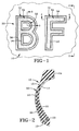
- Pattern 30 may include letters as depicted in FIG. 1, pictorial elements, geometric objects, or combinations of these items.
- the high impact structure of the present invention functions similarly with each type of pattern 30 that may be formed on sidewall 10.
- pattern 30 is represented by a pair of alphabetic characters, namely, the letters B and F. These letters are used for the purpose of providing an example only and no unnecessary limitations to the scope of the present invention are to be derived from their exemplary use.
- Each element of pattern 30 includes an outline wall, generally indicated by the numeral 32, and an interior wall, generally indicated by the numeral 34.
- Each wall 32 and 34 projects outwardly from the outer plane of body 12 in which outer surface 16 is disposed.
- a groove 36 is disposed between outline wall 32 and interior wall 34. Groove 36 increases the visual impact and visibility of pattern 30. Groove 36 functions by creating a shadow line between interior wall 34 and outline wall 32.
- outline wall 32 extends about the entire periphery and interior periphery of each interior wall 34 in the embodiment of the invention depicted in the drawings, outline wall 32 and groove 36 may only extend about a portion of an element of pattern 30 in other embodiments of the present invention.
- Outline wall 32 includes a body 40 that defines an inner surface 42, an outer surface 44 and an upper surface 46.
- Inner surface 42 and outer surface 44 may be disposed substantially normal to the plane of outer surface 16 of body 12 such that each surface 42 and 44 is disposed at substantially a right angle with respect to upper surface 46 as shown in FIG. 6.
- outer surface 44 forms an obtuse angle with the plane of outer surface 16 of body 12.
- inner surface 42 may also form an obtuse angle with outer surface 16.
- the obtuse angle formed between outer surface 44 and outer surface 16 is larger than the obtuse angle formed between inner surface 42 and outer surface 16.
- Upper surface 46 may be substantially parallel to outer surface 16 or may be disposed at an angle.
- outer surface 44 and inner surface 42 may converge at a peak or be joined by a rounded peak.
- Interior wall 34 also has a body 50 that defines a sidewall 52 and an upper surface 54.
- sidewall 52 of interior wall 34 may be substantially normal to outer surface 16 of body 12 as depicted in FIG. 4.
- Sidewall 52 may, however, form an obtuse angle with outer surface 16 as depicted in FIG. 5.
- Upper surface 54 may be substantially parallel to outer surface 16 or may be angled with respect to outer surface 16.
- a plurality of ridges 56 extend upwardly from upper surface 54 to provide texture to inner wall 34. Ridges 56 may be any of a variety of ridge shapes known in the art and may be disposed parallel to one another or may be disposed in other arrangements.
- groove 36 includes a lower surface 60 that is substantially coplanar with or disposed above outer surface 16 of body 12. As can be seen in the figures, both upper surface 46 and upper surface 54 are disposed above lower surface 60 of groove 36. In the embodiment of the invention depicted in the drawings, upper surface 46 of outline wall 32 is also disposed above upper surface 54 of interior wall 34. In other embodiments of the present invention, lower surface 60 of groove 36 may be disposed above outer surface 16 of sidewall 10 with upper surface 54 of interior wall being disposed still above lower surface 60 with upper surface 46 of outline wall 32 being again disposed above upper surface 54.
- the wall structure that forms pattern 30 may be created by a mold that is relatively inexpensive and easy to fabricate.
- relatively inexpensive and easy it is meant that large portions of mold 70 do not have to be removed in order to recess pattern 30 into sidewall 10. Large portions of mold 70 do not have to be removed because no portion of mold 70 extends across the plane 80 of outer surface 72.
- Mold 70 has an outer surface 72 that is pressed against outer surface 16 of sidewall 10 when pattern 30 is formed.
- Pattern 30 is constructed such that mold 70 may be formed simply by removing the area of material that corresponds to each of outline wall 32 and interior wall 34. For example, area 74 and area 76 must be removed from mold 70 to form outline walls 32 while area 78 must be removed from mold 70 to form interior wall 34.
- Removing areas 74, 76 and 78 is relatively easy because these areas are small compared to the overall surface of mold 70. Mold 70 would be significantly more difficult and expensive to manufacture if an indentation in pattern 30 extended into body 12 inside outer surface 16. In such a case, a large area of outer surface 72 of mold 70 would have to be removed to create the indentation. Such removal is generally undesired in the mold making art because it increases the expense of fabricating the mold. Pattern 30 avoids such removal and thus provides a significant benefit over other patterns that are recessed into sidewall 10.
- one embodiment of the present invention has an outline wall 32 that is approximately 0.035 inches tall, an interior wall 34 that is approximately 0.010 inches tall, and a groove 36 that is approximately 0.10 inches wide at its lower surface 60.
- outer surface 44 may form a 120 degree angle with outer surface 16 while inner surface 42 may form a 105 degree angle with outer surface 16.
- Sidewall 52 of interior wall 34 may form a 105 degree angle with outer surface 16.
- Other configuration of pattern 30 are also contemplated.
- Design pattern 30 is depicted in an alternative embodiment of tire sidewall 10 in FIG. 8.
- the structure of pattern 30 is substantially similar to the structure described above in that each element of pattern 30 includes an outline wall 32, an interior wall 34 with a groove 36 disposed between each outline wall 32 and interior wall 34.
- each element 32, 34 of pattern 30 only extends above outer surface 16 of tire sidewall 10.
- tire sidewall 10 includes a textured pattern 100 that includes a plurality of upstanding ribs 102 that are substantially parallel to one another.
- Pattern 100 may also include a middle section of ribs 104 that are differently shaped than ribs 102 to create the appearance of a line through pattern 100.
- Ribs 102 and 104 do not project above the height of outline wall 32 but may project upwardly at a distance that is larger than the height of interior wall 34. No portion of ribs 102 or 104, however, extends below outer surface 16 of tire sidewall 10. Thus, the same benefits in creating the mold are achieved by using pattern 100.
- the improved high impact pattern for a tire sidewall is simplified, provides an effective, safe, inexpensive, and efficient device which achieves all the enumerated objectives of the invention, provides for eliminating difficulties encountered with prior devices, and solves problems and obtains new results in the art.
Landscapes
- Engineering & Computer Science (AREA)
- Mechanical Engineering (AREA)
- Tires In General (AREA)
- Tyre Moulding (AREA)
Applications Claiming Priority (2)
| Application Number | Priority Date | Filing Date | Title |
|---|---|---|---|
| US61954 | 1998-04-17 | ||
| US09/061,954 US6053228A (en) | 1998-04-17 | 1998-04-17 | High impact logo structure for the tire sidewall |
Publications (3)
| Publication Number | Publication Date |
|---|---|
| EP0950548A2 true EP0950548A2 (fr) | 1999-10-20 |
| EP0950548A3 EP0950548A3 (fr) | 2001-03-14 |
| EP0950548B1 EP0950548B1 (fr) | 2004-02-18 |
Family
ID=22039266
Family Applications (1)
| Application Number | Title | Priority Date | Filing Date |
|---|---|---|---|
| EP99250112A Expired - Lifetime EP0950548B1 (fr) | 1998-04-17 | 1999-04-09 | Structure de logo a grand impact visuel pour flanc de bandage pneumatique et procédé de fabrication |
Country Status (7)
| Country | Link |
|---|---|
| US (1) | US6053228A (fr) |
| EP (1) | EP0950548B1 (fr) |
| JP (1) | JP4317286B2 (fr) |
| AR (1) | AR015273A1 (fr) |
| BR (1) | BR9901062A (fr) |
| CA (1) | CA2269152C (fr) |
| DE (1) | DE69914821T2 (fr) |
Cited By (4)
| Publication number | Priority date | Publication date | Assignee | Title |
|---|---|---|---|---|
| EP1260387A3 (fr) * | 2001-05-25 | 2003-05-07 | The Goodyear Tire & Rubber Company | Flanc de pneumatique |
| CN103167962A (zh) * | 2010-08-31 | 2013-06-19 | 株式会社普利司通 | 充气轮胎 |
| CN109153294A (zh) * | 2016-05-26 | 2019-01-04 | 横滨橡胶株式会社 | 充气轮胎 |
| CN115214268A (zh) * | 2021-04-21 | 2022-10-21 | 通伊欧轮胎株式会社 | 充气轮胎 |
Families Citing this family (27)
| Publication number | Priority date | Publication date | Assignee | Title |
|---|---|---|---|---|
| US6955782B1 (en) * | 1999-11-24 | 2005-10-18 | The Goodyear Tire & Rubber Company | Method of molding a tire and mold therefor |
| EP1310384B1 (fr) * | 2001-11-08 | 2014-01-29 | Sumitomo Rubber Industries, Ltd. | Bandage pneumatique pour véhicule |
| WO2003055700A1 (fr) * | 2001-12-26 | 2003-07-10 | Bridgestone Corporation | Pneumatique |
| JP4017457B2 (ja) * | 2002-07-04 | 2007-12-05 | 横浜ゴム株式会社 | 空気入りタイヤ |
| US7387144B2 (en) * | 2005-02-25 | 2008-06-17 | Bridgestone Firestone North American Tire, Llc | Tire having a textured marking and method of making same |
| US7409975B2 (en) * | 2005-05-13 | 2008-08-12 | Bridgestone Firestone North American Tire, Llc | Apparatus for enhancing light reflective properties of tire sidewalls |
| JP2006341830A (ja) * | 2005-06-10 | 2006-12-21 | Toyo Tire & Rubber Co Ltd | 空気入りタイヤ |
| JP5013729B2 (ja) * | 2006-03-27 | 2012-08-29 | 株式会社ブリヂストン | タイヤ |
| JP5054948B2 (ja) * | 2006-09-05 | 2012-10-24 | 株式会社ブリヂストン | タイヤ |
| USD601489S1 (en) | 2008-07-03 | 2009-10-06 | Bridgestone Firestone North American Tire, Llc | Tire sidewall |
| US20100000638A1 (en) * | 2008-07-03 | 2010-01-07 | Scott Smith | Tire having a sidewall with enhanced indicia |
| JP5394679B2 (ja) * | 2008-08-28 | 2014-01-22 | 株式会社ブリヂストン | 空気入りタイヤ |
| JP5232580B2 (ja) * | 2008-09-11 | 2013-07-10 | 株式会社ブリヂストン | 空気入りタイヤ |
| US8061400B2 (en) | 2009-01-05 | 2011-11-22 | The Goodyear Tire & Rubber Company | Fastener assembly secured to a tire sidewall |
| US8061399B2 (en) * | 2009-01-05 | 2011-11-22 | The Goodyear Tire & Rubber Company | Medallion assembly secured to a tire sidewall |
| JP5445092B2 (ja) * | 2009-12-11 | 2014-03-19 | 横浜ゴム株式会社 | 空気入りタイヤ |
| JP5588286B2 (ja) * | 2010-09-27 | 2014-09-10 | 住友ゴム工業株式会社 | 空気入りタイヤ |
| US10062310B2 (en) * | 2012-04-05 | 2018-08-28 | Arcelik Anonim Sirketi | Household appliance comprising a logo and a logo coating method |
| FR3007325B1 (fr) * | 2013-06-21 | 2016-02-12 | Michelin & Cie | Pneumatique comportant un marquage a fort contraste |
| JP6212440B2 (ja) * | 2014-06-18 | 2017-10-11 | 東洋ゴム工業株式会社 | 空気入りタイヤ |
| JP6581336B2 (ja) * | 2014-06-18 | 2019-09-25 | Toyo Tire株式会社 | 空気入りタイヤ |
| JP6747932B2 (ja) * | 2016-10-11 | 2020-08-26 | Toyo Tire株式会社 | 空気入りタイヤ |
| JP7129380B2 (ja) | 2019-06-03 | 2022-09-01 | 株式会社ブリヂストン | タイヤ |
| FR3114772B1 (fr) * | 2020-10-01 | 2022-10-07 | Michelin & Cie | Pneumatique comprenant un insert de flanc |
| JP2022165646A (ja) * | 2021-04-20 | 2022-11-01 | ブラザー工業株式会社 | 樹脂成型品及び樹脂成型品の製造方法 |
| CN113415110A (zh) * | 2021-07-09 | 2021-09-21 | 双钱集团上海轮胎研究所有限公司 | 一种轮胎 |
| JP2024049101A (ja) * | 2022-09-28 | 2024-04-09 | 住友ゴム工業株式会社 | 空気入りタイヤ |
Family Cites Families (13)
| Publication number | Priority date | Publication date | Assignee | Title |
|---|---|---|---|---|
| US1448286A (en) * | 1922-10-25 | 1923-03-13 | Jackson D Comstock | Method of decorating automobile tire casings |
| US2842884A (en) * | 1954-09-02 | 1958-07-15 | Heinn Company | Debossed printed book cover |
| US3518335A (en) * | 1967-04-13 | 1970-06-30 | Uniroyal Inc | Tire vulcanizing method |
| US3769123A (en) * | 1971-03-24 | 1973-10-30 | Goodyear Tire & Rubber | Method of making non-cracking decorative sidewalls of tires |
| US3852145A (en) * | 1973-11-16 | 1974-12-03 | K Kloweit | Sign with inlaid letters |
| US4198774A (en) * | 1977-11-18 | 1980-04-22 | The Goodyear Tire & Rubber Company | Indicia for rubber articles |
| US4284535A (en) * | 1978-08-29 | 1981-08-18 | The Goodyear Tire & Rubber Company | Rubber composites suitable for tire sidewalls from hexadiene polymer |
| US4442618A (en) * | 1982-02-16 | 1984-04-17 | The Goodyear Tire & Rubber Company | Decorative ornamentation for a rubber article and method for making same |
| US4823856A (en) * | 1984-12-19 | 1989-04-25 | The Goodyear Tire & Rubber Company | Serrated outline marking for a tire side wall |
| JP3072921B2 (ja) * | 1991-07-04 | 2000-08-07 | 住友ゴム工業株式会社 | 空気入りタイヤ |
| US5303758A (en) * | 1992-06-15 | 1994-04-19 | The Goodyear Tire & Rubber Company | Tire sidewall design patterns |
| US5645660A (en) * | 1995-06-28 | 1997-07-08 | The Goodyear Tire & Rubber Company | Design patterns for a tire sidewall |
| US5645661A (en) * | 1995-11-09 | 1997-07-08 | The Goodyear Tire & Rubber Company | Tire sidewall |
-
1998
- 1998-04-17 US US09/061,954 patent/US6053228A/en not_active Expired - Lifetime
-
1999
- 1999-04-09 DE DE69914821T patent/DE69914821T2/de not_active Expired - Fee Related
- 1999-04-09 EP EP99250112A patent/EP0950548B1/fr not_active Expired - Lifetime
- 1999-04-14 JP JP10654799A patent/JP4317286B2/ja not_active Expired - Fee Related
- 1999-04-16 AR ARP990101772A patent/AR015273A1/es active IP Right Grant
- 1999-04-16 CA CA002269152A patent/CA2269152C/fr not_active Expired - Fee Related
- 1999-04-16 BR BR9901062-3A patent/BR9901062A/pt not_active IP Right Cessation
Cited By (7)
| Publication number | Priority date | Publication date | Assignee | Title |
|---|---|---|---|---|
| EP1260387A3 (fr) * | 2001-05-25 | 2003-05-07 | The Goodyear Tire & Rubber Company | Flanc de pneumatique |
| CN103167962A (zh) * | 2010-08-31 | 2013-06-19 | 株式会社普利司通 | 充气轮胎 |
| CN103167962B (zh) * | 2010-08-31 | 2016-05-11 | 株式会社普利司通 | 充气轮胎 |
| EP2612771B1 (fr) * | 2010-08-31 | 2018-11-14 | Bridgestone Corporation | Pneumatique |
| CN109153294A (zh) * | 2016-05-26 | 2019-01-04 | 横滨橡胶株式会社 | 充气轮胎 |
| CN109153294B (zh) * | 2016-05-26 | 2020-11-20 | 横滨橡胶株式会社 | 充气轮胎 |
| CN115214268A (zh) * | 2021-04-21 | 2022-10-21 | 通伊欧轮胎株式会社 | 充气轮胎 |
Also Published As
| Publication number | Publication date |
|---|---|
| DE69914821D1 (de) | 2004-03-25 |
| US6053228A (en) | 2000-04-25 |
| CA2269152C (fr) | 2008-06-17 |
| EP0950548B1 (fr) | 2004-02-18 |
| JPH11321241A (ja) | 1999-11-24 |
| EP0950548A3 (fr) | 2001-03-14 |
| DE69914821T2 (de) | 2004-07-29 |
| JP4317286B2 (ja) | 2009-08-19 |
| BR9901062A (pt) | 2000-01-04 |
| CA2269152A1 (fr) | 1999-10-17 |
| AR015273A1 (es) | 2001-04-18 |
Similar Documents
| Publication | Publication Date | Title |
|---|---|---|
| CA2269152C (fr) | Logo a grande resistance sculpte dans le flanc d'un pneu | |
| AU2011249396B2 (en) | Pneumatic tire | |
| CN102066137B (zh) | 充气轮胎 | |
| EP1310384B1 (fr) | Bandage pneumatique pour véhicule | |
| US4198774A (en) | Indicia for rubber articles | |
| US5645660A (en) | Design patterns for a tire sidewall | |
| US11273675B2 (en) | Tire | |
| EP3900958B1 (fr) | Pneu | |
| USD471151S1 (en) | Tire tread | |
| USD464025S1 (en) | Tire tread | |
| USD462314S1 (en) | Tire tread | |
| JP2010052471A (ja) | 空気入りタイヤ | |
| JPH0986106A (ja) | 空気入りタイヤ | |
| US20180099530A1 (en) | Pneumatic tire | |
| JPH06340208A (ja) | 識別文字を有したタイヤ | |
| USD492933S1 (en) | Tire tread | |
| JP2003146025A (ja) | タイヤ | |
| JPH0948217A (ja) | 多数のリッジよりなる装飾体を備えた空気入りタイヤ | |
| USD497144S1 (en) | Tire tread | |
| USD405400S (en) | Tire tread | |
| USD491887S1 (en) | Tire tread | |
| MXPA99003424A (en) | High impact logo structure for neumat side wall | |
| USD480046S1 (en) | Tire tread | |
| USD497592S1 (en) | Tire tread | |
| USD464021S1 (en) | Tire tread |
Legal Events
| Date | Code | Title | Description |
|---|---|---|---|
| PUAI | Public reference made under article 153(3) epc to a published international application that has entered the european phase |
Free format text: ORIGINAL CODE: 0009012 |
|
| AK | Designated contracting states |
Kind code of ref document: A2 Designated state(s): DE ES FR GB IT |
|
| AX | Request for extension of the european patent |
Free format text: AL;LT;LV;MK;RO;SI |
|
| PUAL | Search report despatched |
Free format text: ORIGINAL CODE: 0009013 |
|
| AK | Designated contracting states |
Kind code of ref document: A3 Designated state(s): AT BE CH CY DE DK ES FI FR GB GR IE IT LI LU MC NL PT SE |
|
| AX | Request for extension of the european patent |
Free format text: AL;LT;LV;MK;RO;SI |
|
| 17P | Request for examination filed |
Effective date: 20010319 |
|
| AKX | Designation fees paid |
Free format text: DE ES FR GB IT |
|
| RAP1 | Party data changed (applicant data changed or rights of an application transferred) |
Owner name: BRIDGESTONE/FIRESTONE NORTH AMERICA TIRE LLC |
|
| 17Q | First examination report despatched |
Effective date: 20021018 |
|
| GRAP | Despatch of communication of intention to grant a patent |
Free format text: ORIGINAL CODE: EPIDOSNIGR1 |
|
| RTI1 | Title (correction) |
Free format text: HIGH IMPACT LOGO STRUCTURE FOR TIRE SIDEWALL AND ITS MANUFACTURING METHOD |
|
| GRAS | Grant fee paid |
Free format text: ORIGINAL CODE: EPIDOSNIGR3 |
|
| GRAA | (expected) grant |
Free format text: ORIGINAL CODE: 0009210 |
|
| AK | Designated contracting states |
Kind code of ref document: B1 Designated state(s): DE ES FR GB IT |
|
| PG25 | Lapsed in a contracting state [announced via postgrant information from national office to epo] |
Ref country code: IT Free format text: LAPSE BECAUSE OF FAILURE TO SUBMIT A TRANSLATION OF THE DESCRIPTION OR TO PAY THE FEE WITHIN THE PRE;WARNING: LAPSES OF ITALIAN PATENTS WITH EFFECTIVE DATE BEFORE 2007 MAY HAVE OCCURRED AT ANY TIME BEFORE 2007. THE CORRECT EFFECTIVE DATE MAY BE DIFFERENT FROM THE ONE RECORDED.SCRIBED TIME-LIMIT Effective date: 20040218 Ref country code: ES Free format text: LAPSE BECAUSE OF FAILURE TO SUBMIT A TRANSLATION OF THE DESCRIPTION OR TO PAY THE FEE WITHIN THE PRESCRIBED TIME-LIMIT Effective date: 20040218 |
|
| REG | Reference to a national code |
Ref country code: GB Ref legal event code: FG4D |
|
| REF | Corresponds to: |
Ref document number: 69914821 Country of ref document: DE Date of ref document: 20040325 Kind code of ref document: P |
|
| PGFP | Annual fee paid to national office [announced via postgrant information from national office to epo] |
Ref country code: ES Payment date: 20040423 Year of fee payment: 6 |
|
| ET | Fr: translation filed | ||
| PLBE | No opposition filed within time limit |
Free format text: ORIGINAL CODE: 0009261 |
|
| STAA | Information on the status of an ep patent application or granted ep patent |
Free format text: STATUS: NO OPPOSITION FILED WITHIN TIME LIMIT |
|
| 26N | No opposition filed |
Effective date: 20041119 |
|
| PGFP | Annual fee paid to national office [announced via postgrant information from national office to epo] |
Ref country code: GB Payment date: 20090312 Year of fee payment: 11 |
|
| PGFP | Annual fee paid to national office [announced via postgrant information from national office to epo] |
Ref country code: FR Payment date: 20090406 Year of fee payment: 11 Ref country code: DE Payment date: 20090430 Year of fee payment: 11 |
|
| GBPC | Gb: european patent ceased through non-payment of renewal fee |
Effective date: 20100409 |
|
| REG | Reference to a national code |
Ref country code: FR Ref legal event code: ST Effective date: 20101230 |
|
| PG25 | Lapsed in a contracting state [announced via postgrant information from national office to epo] |
Ref country code: DE Free format text: LAPSE BECAUSE OF NON-PAYMENT OF DUE FEES Effective date: 20101103 |
|
| PG25 | Lapsed in a contracting state [announced via postgrant information from national office to epo] |
Ref country code: GB Free format text: LAPSE BECAUSE OF NON-PAYMENT OF DUE FEES Effective date: 20100409 |
|
| PG25 | Lapsed in a contracting state [announced via postgrant information from national office to epo] |
Ref country code: FR Free format text: LAPSE BECAUSE OF NON-PAYMENT OF DUE FEES Effective date: 20100430 |