EP0950562A2 - Verrou - Google Patents
Verrou Download PDFInfo
- Publication number
- EP0950562A2 EP0950562A2 EP99107192A EP99107192A EP0950562A2 EP 0950562 A2 EP0950562 A2 EP 0950562A2 EP 99107192 A EP99107192 A EP 99107192A EP 99107192 A EP99107192 A EP 99107192A EP 0950562 A2 EP0950562 A2 EP 0950562A2
- Authority
- EP
- European Patent Office
- Prior art keywords
- base
- shaft
- locking
- frame
- locking element
- Prior art date
- Legal status (The legal status is an assumption and is not a legal conclusion. Google has not performed a legal analysis and makes no representation as to the accuracy of the status listed.)
- Granted
Links
- 210000001331 nose Anatomy 0.000 description 5
- 241000388002 Agonus cataphractus Species 0.000 description 4
- 238000012423 maintenance Methods 0.000 description 3
- 238000013459 approach Methods 0.000 description 1
- 230000009286 beneficial effect Effects 0.000 description 1
- 230000001419 dependent effect Effects 0.000 description 1
- 238000003780 insertion Methods 0.000 description 1
- 230000037431 insertion Effects 0.000 description 1
- 238000004519 manufacturing process Methods 0.000 description 1
- 230000035939 shock Effects 0.000 description 1
Images


Classifications
-
- B—PERFORMING OPERATIONS; TRANSPORTING
- B60—VEHICLES IN GENERAL
- B60P—VEHICLES ADAPTED FOR LOAD TRANSPORTATION OR TO TRANSPORT, TO CARRY, OR TO COMPRISE SPECIAL LOADS OR OBJECTS
- B60P7/00—Securing or covering of load on vehicles
- B60P7/06—Securing of load
- B60P7/13—Securing freight containers or forwarding containers on vehicles
Definitions
- the invention relates to a locking element according to the preamble of claim 1.
- a frame and at least one latch hook or locking hooks are known that a frame and at least one latch hook or locking hooks.
- the locking element known from US Pat. No. 5,265,991 has a frame for fastening the locking element on the Floor of the cargo hold and a plinth that swivels is attached to the frame.
- the base points to his End facing away from the frame two hook noses pointing away from each other on, which are integrally connected to the base and with the base are pivotable.
- the arrangement of frames, The base and hook nose formed on the base is such that the hooked nose on the holding bar of a freight container, which is in its final stowed position rests and the freight container against vertical and lateral slippage ensures.
- the base also forms one lateral guidance in the transport of the freight container in its final stowed position.
- the base can be used together with the hook lugs from its vertical working position on the left in a rest position and on the right in a folded away position Position pivoted below the cargo floor become.
- a spring brings the base together with those on it molded hook noses from the folded position or from the rest position to the vertical working position.
- In the latching position is held by a manually operated latch Detachable base in the locking position.
- the invention has for its object a locking element of the type mentioned to further develop that increased security with little effort is given.
- a first important aspect of the invention is that Locking hook not in one piece on the opposite.
- the framework of the Bolt element to attach pivotable base, but to provide the base with at least one locking hook, which is pivotable relative to the base of the locking element is. If a container or the like drives the invention Latching element on the side, the base folds in the direction of movement and with it the swiveling locking hook Path. This will jam the container with the Locking element effectively prevented, and the container or the like can be in its final stowed position without jamming to be brought.
- a possibly swiveled base aligns get into its vertical working or locking position, and the locking hook that can be swiveled on the base also in its working or locking position above pivot a holding bar of the container or the like and so the container against a lateral or vertical Secure it from slipping. Since the locking element according to the invention Operating personnel can not get jammed with the container the container quickly and easily in its bring the final stowage position and use force the container against the locking element is omitted.
- Another important aspect of the invention is in the side surface of the base facing the container Cutout or breakthrough to accommodate a deflection or Guide roller should be provided slightly over the side surface of the base protrudes. This makes transportation easier of the container or the like in its final stowed position. In addition, the deflection roller catches shocks during transportation of the container into its final stowed position and reduced additionally the risk of damage to the invention Locking element. Because of the deflector, it is also possible, the maintenance intervals for the invention Extend locking element without sacrificing security suffers from this. Instead of an exchange of the invention Bolt element, it is often sufficient, only that To replace deflector pulley.
- the deflection roller is on the pivot axis of the locking hook running through the base to store, so that with a few simple steps, e.g. in the Framework of maintenance work, both the deflection roller as well the locking hook can be replaced.
- the multifunctional use of the swivel axis or shaft for Swiveling the locking hook on further elements can be dispensed with and the locking element according to the invention is light and small.
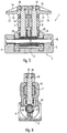
- FIGs 1, 5 and 6 is a locking element according to the invention with a frame 2 and a pivotable in the frame 2 Socket 6 in its working or locking position shown.
- a first locking hook 10 and a second locking hook 11 arranged, each parallel to the top surface 9 of the Base 6 are pivotable.
- the U-shaped frame 2 has a bottom 3, a first side part 4 and a second side part 5 on. In the first side part 4 and the second side part 5, the ends of a third shaft 18 are mounted.
- the U-shaped section of the frame 2 is the lower end of the base 6, which surrounds the third shaft 18 and this on the shaft 18 in the manner of a connecting rod stored and pivotable relative to the frame 2.
- the third shaft 18 is in the region of the U-shaped section of the Frame 2 surrounded by a third spring 23.
- An end to Spring 23 is connected to the lower end of the base 6, and the other end of the spring 23 is with the frame 2 connected that the spring 23 the base 6 at its deflection from the vertical working position with a spring force acts on the base 6, in the absence of action an external force, from one in the Y direction or opposite pivoted position in its opposite the frame 2 vertical working position moved back. This turns the lower end of the Base 6 around the third shaft 18.
- first shaft 16 and a second shaft 17 rotatably mounted in the base 6 . Both shafts 16 and 17 are spaced apart to each other and run in the Z direction. That from the top surface 9 of the base 6 protruding end of the first shaft 16 and the end protruding from the top surface 9 of the base 6 the second shaft 17 have a slightly tapered end and then an external thread on the outside.
- the tapered The end of the first shaft 16 takes the locking hook 10 on and the taper of the first shaft 16 is with a partially and complementarily tapered bore in the first locking hook 10 engages, reducing the height of the first locking hook 10 on the first shaft 16 above the top surface 9 is defined.
- the Z position of the second locking hook 11 above the top surface 9 defines and so defined conditions when pivoting the first locking hook 10 and the second locking hook 11 allows on the top surface 9 of the base 6.
- the Z direction is the position of the first locking hook 10 by a Nut 26 on the male thread at the outer end of the first The shaft 16 is screwed on.
- a nut 27 on the external thread of the outer end the second shaft 17 is screwed that the second locking hook 11 unintentionally by the second shaft 17 can solve in the Z direction.
- the first pivotable locking hook 10 and the second pivotable Locking hooks 11 each have the shape of a Nose and are preferably form-fitting (not shown) such on the associated first and second shafts 16 and 17 attached that the first locking hook 10 against the X direction and the second locking hook 11 points in the X direction.
- the first locking hook 10 has a flat lower surface 12, the extends largely parallel to the bottom 3 of the frame 2. Especially because of a weight saving, is the first Locking hook 10 provided with a semi-open triangular groove 14.
- the second locking hook identical to the first locking hook 10 11 also has a flat lower surface 13, which runs parallel to the bottom 3 of the frame 2 and also is provided with a semi-open triangular groove 15.
- the lower end of the first shaft 16 running in the base 6 is surrounded by a first spring 24 (cf. FIGS. 4 and 5), whose first end on the base 6 and the second end the rotatable shaft 16 is fixed so that the first Spring 24 the first shaft 16 when the first is deflected Locking hook 10 from its counter-X direction Working position with a spring force that the pivotable first locking hook 10, in the absence of The action of an external force, moved back to its working position.
- the first shaft 16 rotates in the base 6.
- the base 6 In the X direction, the base 6 has a horizontal opening on. In the area of the horizontal breakthrough of the Base 6 encloses a first deflecting roller 7 the first shaft 16 and a second deflection roller 8 the second shaft 17.
- the first Deflection roller 7 is on the first shaft 16 and the second Deflection roller 8 is rotatably mounted on the second shaft 17.
- the first deflection roller 7 protrudes from the opening in the base 6 slightly out of the X direction.
- the second deflection roller 8 protrudes slightly in the X direction out of the opening of the base 6 and forms a guide for the holding bar one in a final Stowage container or the like that is in the final stowed position in the vertical direction through the Locking hook and in the lateral direction through the base 6 at least one locking element 1 is held.
- Figure 2 shows the locking element according to Figure 1 in plan view.
- the reference symbol 11a shows the second locking hook 11 in its working position
- reference numeral 11b shows the locking hook 11 in a counterclockwise direction 45 ° swiveled position (shown in dashed lines)
- the position symbol 11c shows the second locking hook 11 in a 90 ° counterclockwise direction from its Working position swiveled second locking hook (also shown in dashed lines).
- the second Locking hook 11 from its working position in the direction of Pivoted clockwise at least in the range of 0 to 90 ° (not shown).
- the first locking hook 10 preferably also over an area from 0 to 90 ° in both directions around its working position pivot when an external force, for example through a passing container, a Freight pallet or other freight, at first or second locking hook is exercised.
- Figure 3 shows the locking element according to Figure 1 with a about 90 ° relative to the frame 2 from its working position in Perspective overall view of the pivoted base.
- the "folding away" of the Socket in the Y direction occurs especially when a containers or the like approaching in the Y direction opens against the base 6 of the locking element 1 and the Base 6 flipped over, so that the container lock element 1 can happen largely unhindered.
- the base can also be used in the opposite Y direction (not shown).
- Figure 4 shows the locking element 1 according to Figure 3 in one Side view and the arrangement of the locking element 1 in one Intermediate shelf 21 below the cargo compartment floor 19 in the folded away position Position.
- Bolt element several times along parallel lines in one Intermediate floor below the floor of the cargo hold, in particular the cargo hold of an aircraft.
- the distance the parallel lines along which the invention Bolt elements 1 are provided preferably corresponds largely the distance of a so-called half container.
- the whole container is between the left and right lines along which the invention Bolt elements 1 are arranged, transported.
- one on the left and one on the right preferably on the ground of the entire container provided mounting bracket left and right locking hooks and sets the base 6 of the first locking element 1 on the middle line between the left and right lines in the direction of transport.
- the locking hooks may swivel into their working position back and overlap the holding strips of the container, see above that a secure mounting of the container against lateral or vertical sliding of the container is enabled.
- the base is preferably both counterclockwise as well as swiveling clockwise. The same applies to the locking hooks that can be swiveled on the base. This can jam the container between prevented two rows with locking elements according to the invention regardless of whether the container from a first direction or an opposite direction to the first direction Directed to its final stowed position becomes.
- a largely effortless insertion of the container will be in its final stowed position in particular also favored in that the base of the invention
- Bolt element is provided with deflection rollers that hold the holding strips of the container.
Landscapes
- Engineering & Computer Science (AREA)
- Transportation (AREA)
- Mechanical Engineering (AREA)
- Connection Of Plates (AREA)
- Package Frames And Binding Bands (AREA)
- Pallets (AREA)
- Closures For Containers (AREA)
Applications Claiming Priority (2)
| Application Number | Priority Date | Filing Date | Title |
|---|---|---|---|
| DE19816892A DE19816892C2 (de) | 1998-04-16 | 1998-04-16 | Riegel |
| DE19816892 | 1998-04-16 |
Publications (3)
| Publication Number | Publication Date |
|---|---|
| EP0950562A2 true EP0950562A2 (fr) | 1999-10-20 |
| EP0950562A3 EP0950562A3 (fr) | 2002-05-15 |
| EP0950562B1 EP0950562B1 (fr) | 2006-06-21 |
Family
ID=7864729
Family Applications (1)
| Application Number | Title | Priority Date | Filing Date |
|---|---|---|---|
| EP99107192A Expired - Lifetime EP0950562B1 (fr) | 1998-04-16 | 1999-04-13 | Verrou |
Country Status (3)
| Country | Link |
|---|---|
| US (1) | US6270300B1 (fr) |
| EP (1) | EP0950562B1 (fr) |
| DE (2) | DE19816892C2 (fr) |
Cited By (3)
| Publication number | Priority date | Publication date | Assignee | Title |
|---|---|---|---|---|
| CN112124346A (zh) * | 2020-10-12 | 2020-12-25 | 中车青岛四方机车车辆股份有限公司 | 限位机构及具有该限位机构的轨道车辆的车厢 |
| US10919630B1 (en) * | 2019-08-13 | 2021-02-16 | Goodrich Corporation | Restraint assembly for cargo system |
| US20220297838A1 (en) * | 2021-03-19 | 2022-09-22 | Goodrich Corporation | Attenuated roller restraint for aircraft cargo loading systems |
Families Citing this family (30)
| Publication number | Priority date | Publication date | Assignee | Title |
|---|---|---|---|---|
| DE19961734C1 (de) * | 1999-12-21 | 2001-03-01 | Eads Airbus Gmbh | Frachtladesystem für ein Flugzeug zum Be- und/oder Entladen von Beladungseinheiten |
| US6450744B1 (en) * | 2001-02-23 | 2002-09-17 | The Boeing Company | Overrideable vertical restraint for cargo handling systems |
| US6485238B2 (en) * | 2001-03-16 | 2002-11-26 | Pemco Aviation Group | Restraint apparatus |
| GB2393704B (en) * | 2002-10-02 | 2006-03-15 | Aircraft Materials Ltd | Improvements to an aerial delivery system and restraint assembly therefor |
| US7429157B2 (en) * | 2005-10-13 | 2008-09-30 | Goodrich Corporation | Overrideable guide and vertical restraint for an air cargo system |
| US7435043B2 (en) * | 2005-10-14 | 2008-10-14 | Goodrich Corporation | Air cargo vertical restraint assembly |
| GB2440063B (en) * | 2005-10-14 | 2008-05-21 | Goodrich Corp | Air cargo vertical restraint assembly |
| US7665938B2 (en) * | 2006-03-30 | 2010-02-23 | Goodrich Corporation | Coaxially mounted retracting guide and restraint for an air cargo system |
| US7731460B2 (en) | 2006-10-30 | 2010-06-08 | Goodrich Corporation | Self-adjusting ULD loading guide and restraint |
| FR2916422B1 (fr) * | 2007-05-25 | 2016-09-30 | Goodrich Corp | Procede de modification de la soute d'un avion cargo pour recevoir des palettes standard de differentes longueurs,kit de mise en oeuvre et avion ainsi equipe |
| CA2661787A1 (fr) * | 2008-04-07 | 2009-10-07 | Gaston Morin | Dispositif d'arrimage automatique pour conteneurs |
| US7988391B2 (en) | 2009-02-17 | 2011-08-02 | Goodrich Corporation | Self-locking, overrideable and attenuating cargo guide and restraint |
| US8221038B1 (en) | 2010-02-26 | 2012-07-17 | Angra International, LLC. | Overridable side lock (stabber) pallet type load restraint |
| DE102010017535B4 (de) * | 2010-06-23 | 2018-10-25 | Telair International Gmbh | Befestigungseinrichtung zum zumindest teilweisen Sichern eines ersten und eines zweiten Frachtstücks |
| US8337127B2 (en) | 2011-04-26 | 2012-12-25 | Ancra International, Llc | Latch arrangement for cargo restraint |
| DE102012104235B4 (de) | 2012-05-15 | 2016-08-11 | Telair International Gmbh | Verriegelungseinrichtung zum Sichern und/oder Führen mindestens eines Frachtstücks |
| US9663021B1 (en) | 2016-03-24 | 2017-05-30 | Northrop Grumman Systems Corporation | Expanding clamping twistlock for ISO aperture securement |
| US10392111B2 (en) * | 2017-03-23 | 2019-08-27 | Goodrich Corporation | Semi-automated lock assembly |
| CN109017538B (zh) * | 2018-08-29 | 2023-06-27 | 今创集团股份有限公司 | 地锁及采用该地锁的货柜固定系统 |
| US11345475B2 (en) * | 2019-08-13 | 2022-05-31 | Goodrich Corporation | Stowable cargo guide for cargo roller trays |
| US10919433B1 (en) * | 2019-08-13 | 2021-02-16 | Goodrich Corporation | Restraint assembly for cargo system |
| EP3858965B1 (fr) * | 2020-01-28 | 2022-05-11 | The Procter & Gamble Company | Produit de nettoyage |
| EP3858961A1 (fr) | 2020-01-28 | 2021-08-04 | The Procter & Gamble Company | Produit de nettoyage |
| US11673505B2 (en) | 2020-03-05 | 2023-06-13 | Goodrich Corporation | Cargo restraint assembly |
| US12234031B2 (en) | 2021-08-09 | 2025-02-25 | Goodrich Corporation | Cargo restraint system with individually retractable restraints |
| CN113954732B (zh) * | 2021-09-24 | 2023-07-18 | 郑州日产汽车有限公司 | 一种隐藏式货箱绳钩 |
| CN113998130B (zh) * | 2021-10-25 | 2024-01-12 | 庆安集团有限公司 | 一种用于限动的电控锁定装置 |
| US12252267B2 (en) | 2021-11-16 | 2025-03-18 | Goodrich Corporation | Restraint system utilizing co-axial actuation |
| CN116729627B (zh) * | 2023-08-14 | 2023-11-07 | 四川腾盾科技有限公司 | 一种空投锁及其工作方法 |
| DE102024002644A1 (de) * | 2024-08-15 | 2026-02-19 | Jost-Werke Deutschland Gmbh | Verriegelungsvorrichtung zur Aufnahme und Freigabe von einem auf einem Fahrzeugchassis abstellbaren Container oder Wechselbehälter |
Citations (1)
| Publication number | Priority date | Publication date | Assignee | Title |
|---|---|---|---|---|
| US5265991A (en) | 1992-10-30 | 1993-11-30 | Aar Corp. | Retractable cargo restraint and cargo restraining system |
Family Cites Families (19)
| Publication number | Priority date | Publication date | Assignee | Title |
|---|---|---|---|---|
| US3465998A (en) * | 1967-04-28 | 1969-09-09 | Mc Donnell Douglas Corp | Restraint latch |
| US3447665A (en) | 1967-06-15 | 1969-06-03 | Cragomatic Inc | Cargo load carrier enabling universal movement of cargo load thereon and thereover |
| GB1256377A (en) | 1969-05-21 | 1971-12-08 | Western Gear Corp | Torque controlled power roller for conveyor system |
| US3712454A (en) | 1971-02-19 | 1973-01-23 | Republic Nat Bank Of Dallas | Powered roller mechanism |
| US3741508A (en) * | 1971-05-06 | 1973-06-26 | Boeing Co | Cargo handling system side locking device |
| US3906870A (en) * | 1974-06-24 | 1975-09-23 | Boeing Co | Retractable cargo restraint and center guide for cargo compartments |
| US4589542A (en) | 1983-12-19 | 1986-05-20 | The Boeing Company | Cargo drive unit |
| DE3828232A1 (de) | 1988-08-19 | 1990-02-22 | Bavaria Cargo Tech | Antriebsrolleneinheit |
| DE3919613A1 (de) | 1989-06-15 | 1990-12-20 | Electro Pneumatic Int | Rollenantriebseinheit |
| US5011348A (en) * | 1989-12-15 | 1991-04-30 | The Boeing Company | Automatically retractable centerline restraint |
| EP0497045B1 (fr) | 1991-01-30 | 1995-02-22 | Teleflex Incorporated | Unité de roulement pour un plancher de chargement |
| DE4200985C2 (de) | 1991-01-31 | 1994-05-05 | Bavaria Cargo Tech | Elektronische Steueranordnung für Antriebsrolleneinheiten |
| US5183150A (en) | 1991-12-13 | 1993-02-02 | Allied-Signal Inc. | Cargo drive unit with a hysteresis coupling |
| DE4210702C2 (de) * | 1992-04-01 | 1995-09-21 | Daimler Benz Aerospace Airbus | Vorrichtung zur Führung |
| DE4224819C1 (fr) * | 1992-07-27 | 1993-08-19 | Electro Pneumatic International Gmbh, 8164 Hausham, De | |
| DE4336978C2 (de) | 1993-10-29 | 1995-08-24 | Elektro Metall Exp Gmbh | Antriebseinheit, insbesondere für eine Verladeeinrichtung in einem Flugzeug |
| US5568858A (en) | 1994-10-20 | 1996-10-29 | Vickers, Incorporated | Power drive unit for aircraft cargo handling systems |
| DE69604163D1 (de) | 1995-03-13 | 1999-10-14 | James Kevin Hurson | Verfahren und vorrichtung zur überwachung der griffigkeit von fahrbahnen |
| US5573359A (en) * | 1995-05-08 | 1996-11-12 | Ancra International Corporation | Cargo securing device |
-
1998
- 1998-04-16 DE DE19816892A patent/DE19816892C2/de not_active Expired - Lifetime
-
1999
- 1999-04-13 DE DE59913574T patent/DE59913574D1/de not_active Expired - Lifetime
- 1999-04-13 EP EP99107192A patent/EP0950562B1/fr not_active Expired - Lifetime
- 1999-04-15 US US09/293,461 patent/US6270300B1/en not_active Expired - Lifetime
Patent Citations (1)
| Publication number | Priority date | Publication date | Assignee | Title |
|---|---|---|---|---|
| US5265991A (en) | 1992-10-30 | 1993-11-30 | Aar Corp. | Retractable cargo restraint and cargo restraining system |
Cited By (5)
| Publication number | Priority date | Publication date | Assignee | Title |
|---|---|---|---|---|
| US10919630B1 (en) * | 2019-08-13 | 2021-02-16 | Goodrich Corporation | Restraint assembly for cargo system |
| US20210047040A1 (en) * | 2019-08-13 | 2021-02-18 | Goodrich Corporation | Restraint assembly for cargo system |
| CN112124346A (zh) * | 2020-10-12 | 2020-12-25 | 中车青岛四方机车车辆股份有限公司 | 限位机构及具有该限位机构的轨道车辆的车厢 |
| US20220297838A1 (en) * | 2021-03-19 | 2022-09-22 | Goodrich Corporation | Attenuated roller restraint for aircraft cargo loading systems |
| US12162624B2 (en) * | 2021-03-19 | 2024-12-10 | Goodrich Corporation | Attenuated roller restraint for aircraft cargo loading systems |
Also Published As
| Publication number | Publication date |
|---|---|
| US6270300B1 (en) | 2001-08-07 |
| DE19816892C2 (de) | 2000-05-18 |
| DE19816892A1 (de) | 1999-11-04 |
| DE59913574D1 (de) | 2006-08-03 |
| EP0950562A3 (fr) | 2002-05-15 |
| EP0950562B1 (fr) | 2006-06-21 |
Similar Documents
| Publication | Publication Date | Title |
|---|---|---|
| DE19816892C2 (de) | Riegel | |
| EP3638596B1 (fr) | Récipient à grande capacité muni d'un rabat articulé | |
| DE19523284A1 (de) | Rollender Katalogkoffer mit ausziehbarem Handgriff | |
| DE102004056858A1 (de) | Fördereinrichtung | |
| EP2759428A2 (fr) | Chariot à galets latéraux et courroie de guidage avec rail pour une structure de toit coulissant d'une carrosserie de véhicule ou d'un conteneur | |
| EP3210808B1 (fr) | Enrouleur de bâche et véhicule utilitaire équipé d'une bâche | |
| EP0413884A1 (fr) | Récipient pliable | |
| DE10258439B4 (de) | Verriegelungseinrichtung für Frachtladesysteme | |
| DE4237410C2 (de) | Pritschenaufbau für LKW-Wechselbehälter und Festaufbauten | |
| EP3909807A1 (fr) | Véhicule | |
| DE9216912U1 (de) | Pritsche für einen Lastkraftwagen und/oder Anhänger | |
| DE102021111856B3 (de) | Verriegelungsvorrichtung und Frachtdeck | |
| DE3922811A1 (de) | Vorrichtung zur aufnahme eines containers | |
| DE1956392C3 (de) | Zusammenschiebbares Verdeck, insbesondere für Lastkraftwagen und -anhänger | |
| DE19620909A1 (de) | Zusammenklappbares Flachgestell mit Auffahrt und Wandungen | |
| DE69204758T2 (de) | Runge für eine Ladefläche und Methode zum Montieren einer Schliess- und Beeinflussungsvorrichtung in dieser. | |
| DE68911011T2 (de) | Behälter mit horizontal abnehmbaren Seitenelementen. | |
| DE4204464C1 (en) | Magazine for transporting cheque, credit or identification card(s) - has cards stacked in channel section duct with spring loaded latches in side walls as base | |
| EP0581071A1 (fr) | Elément de verrouillage | |
| DE19905909A1 (de) | Vorrichtung zum Verbinden und Lösen übereinandergestapelter Behälter | |
| DE202021104791U1 (de) | Transportfahrzeug mit Arretiereinrichtung | |
| DE202023106586U1 (de) | Transportfahrzeug | |
| DE20214388U1 (de) | Lastenträger, insbesondere Fahrradträger | |
| DE9403507U1 (de) | Güterwagen | |
| DE8910163U1 (de) | Zusammenlegbarer Behälter |
Legal Events
| Date | Code | Title | Description |
|---|---|---|---|
| PUAI | Public reference made under article 153(3) epc to a published international application that has entered the european phase |
Free format text: ORIGINAL CODE: 0009012 |
|
| AK | Designated contracting states |
Kind code of ref document: A2 Designated state(s): AT BE CH CY DE DK ES FI FR GB GR IE IT LI LU MC NL PT SE |
|
| AX | Request for extension of the european patent |
Free format text: AL;LT;LV;MK;RO;SI |
|
| PUAL | Search report despatched |
Free format text: ORIGINAL CODE: 0009013 |
|
| AK | Designated contracting states |
Kind code of ref document: A3 Designated state(s): AT BE CH CY DE DK ES FI FR GB GR IE IT LI LU MC NL PT SE |
|
| AX | Request for extension of the european patent |
Free format text: AL;LT;LV;MK;RO;SI |
|
| RIC1 | Information provided on ipc code assigned before grant |
Free format text: 7B 60P 7/13 A, 7B 64D 9/00 B |
|
| 17P | Request for examination filed |
Effective date: 20021023 |
|
| AKX | Designation fees paid |
Designated state(s): DE FR GB |
|
| RAP1 | Party data changed (applicant data changed or rights of an application transferred) |
Owner name: TELAIR INTERNATIONAL GMBH |
|
| GRAP | Despatch of communication of intention to grant a patent |
Free format text: ORIGINAL CODE: EPIDOSNIGR1 |
|
| GRAS | Grant fee paid |
Free format text: ORIGINAL CODE: EPIDOSNIGR3 |
|
| GRAA | (expected) grant |
Free format text: ORIGINAL CODE: 0009210 |
|
| AK | Designated contracting states |
Kind code of ref document: B1 Designated state(s): DE FR GB |
|
| REG | Reference to a national code |
Ref country code: GB Ref legal event code: FG4D Free format text: NOT ENGLISH |
|
| REF | Corresponds to: |
Ref document number: 59913574 Country of ref document: DE Date of ref document: 20060803 Kind code of ref document: P |
|
| GBT | Gb: translation of ep patent filed (gb section 77(6)(a)/1977) |
Effective date: 20060918 |
|
| ET | Fr: translation filed | ||
| PLBE | No opposition filed within time limit |
Free format text: ORIGINAL CODE: 0009261 |
|
| STAA | Information on the status of an ep patent application or granted ep patent |
Free format text: STATUS: NO OPPOSITION FILED WITHIN TIME LIMIT |
|
| 26N | No opposition filed |
Effective date: 20070322 |
|
| REG | Reference to a national code |
Ref country code: FR Ref legal event code: PLFP Year of fee payment: 18 |
|
| REG | Reference to a national code |
Ref country code: FR Ref legal event code: PLFP Year of fee payment: 19 |
|
| REG | Reference to a national code |
Ref country code: FR Ref legal event code: PLFP Year of fee payment: 20 |
|
| PGFP | Annual fee paid to national office [announced via postgrant information from national office to epo] |
Ref country code: DE Payment date: 20180427 Year of fee payment: 20 |
|
| PGFP | Annual fee paid to national office [announced via postgrant information from national office to epo] |
Ref country code: FR Payment date: 20180426 Year of fee payment: 20 |
|
| PGFP | Annual fee paid to national office [announced via postgrant information from national office to epo] |
Ref country code: GB Payment date: 20180424 Year of fee payment: 20 |
|
| REG | Reference to a national code |
Ref country code: DE Ref legal event code: R071 Ref document number: 59913574 Country of ref document: DE |
|
| REG | Reference to a national code |
Ref country code: GB Ref legal event code: PE20 Expiry date: 20190412 |
|
| PG25 | Lapsed in a contracting state [announced via postgrant information from national office to epo] |
Ref country code: GB Free format text: LAPSE BECAUSE OF EXPIRATION OF PROTECTION Effective date: 20190412 |