EP0950632B1 - Kettenzug - Google Patents
Kettenzug Download PDFInfo
- Publication number
- EP0950632B1 EP0950632B1 EP99107130A EP99107130A EP0950632B1 EP 0950632 B1 EP0950632 B1 EP 0950632B1 EP 99107130 A EP99107130 A EP 99107130A EP 99107130 A EP99107130 A EP 99107130A EP 0950632 B1 EP0950632 B1 EP 0950632B1
- Authority
- EP
- European Patent Office
- Prior art keywords
- chain
- housing
- hoist according
- chain hoist
- sprocket housing
- Prior art date
- Legal status (The legal status is an assumption and is not a legal conclusion. Google has not performed a legal analysis and makes no representation as to the accuracy of the status listed.)
- Expired - Lifetime
Links
- 239000000725 suspension Substances 0.000 claims description 16
- 239000000463 material Substances 0.000 claims description 6
- 230000005540 biological transmission Effects 0.000 description 20
- 238000007689 inspection Methods 0.000 description 8
- 238000010276 construction Methods 0.000 description 4
- 210000002414 leg Anatomy 0.000 description 4
- 239000002184 metal Substances 0.000 description 3
- 230000002093 peripheral effect Effects 0.000 description 3
- 239000011343 solid material Substances 0.000 description 3
- 230000000295 complement effect Effects 0.000 description 2
- 238000006073 displacement reaction Methods 0.000 description 2
- 210000003414 extremity Anatomy 0.000 description 2
- 241000555745 Sciuridae Species 0.000 description 1
- 238000005266 casting Methods 0.000 description 1
- 238000001816 cooling Methods 0.000 description 1
- 230000001419 dependent effect Effects 0.000 description 1
- 238000011161 development Methods 0.000 description 1
- 230000018109 developmental process Effects 0.000 description 1
- 230000000694 effects Effects 0.000 description 1
- 230000002349 favourable effect Effects 0.000 description 1
- 230000003993 interaction Effects 0.000 description 1
- 230000003716 rejuvenation Effects 0.000 description 1
- 238000005096 rolling process Methods 0.000 description 1
- 238000010008 shearing Methods 0.000 description 1
- 210000000689 upper leg Anatomy 0.000 description 1
- 238000011144 upstream manufacturing Methods 0.000 description 1
- 238000004804 winding Methods 0.000 description 1
Images


Classifications
-
- B—PERFORMING OPERATIONS; TRANSPORTING
- B66—HOISTING; LIFTING; HAULING
- B66D—CAPSTANS; WINCHES; TACKLES, e.g. PULLEY BLOCKS; HOISTS
- B66D3/00—Portable or mobile lifting or hauling appliances
- B66D3/18—Power-operated hoists
- B66D3/20—Power-operated hoists with driving motor, e.g. electric motor, and drum or barrel contained in a common housing
- B66D3/22—Power-operated hoists with driving motor, e.g. electric motor, and drum or barrel contained in a common housing with variable-speed gearings between driving motor and drum or barrel
Definitions
- DE-A-195 30 891 shows a chain hoist which the closest prior art, consisting from a motor, housed in a gear housing Gear and a sprocket housing, which on the Gearbox is flanged. Chain nut housing and engine are located on the same side of the transmission.
- the sprocket housing has an interior, in the sprocket turns on the transmission output shaft is stored flying. On the gear opposite side is the interior for the sprocket closed with a lid.
- the chain nut housing itself is in two parts and consists from two housing halves, along a parting line are joined together at right angles to the axis of rotation of the Chain nut runs.
- the required chain ejector inserted, with a fastening screw for Screw on the sprocket housing to the gearbox housing passes through the Kettennussauswerfer.
- Each case half consists of a perforated metal plate, which is coated with plastic. At the metal plates of the sprocket housing, the chain hoist can be hung become.
- the known construction is only suitable for chain hoists with low load capacity.
- the outgoing of the hook load Power must go from the sprocket to the gearbox, in which the output shaft is mounted, in the sprocket housing be initiated. Since this to the critical Bodies made of plastic, only small forces be removed.
- the longitudinal division leads, moreover, that the hook load essentially only about those housing half in the Suspension for the chain hoist is initiated, which is the transmission housing is next adjacent.
- the other case half is due to the smooth parting line only friction connected and will be at appropriate load move relative to the other half of the housing.
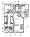
- the chain nut housing exists made of a solid material that has an immediate suspension on the sprocket housing allows. This is the suspension in immediate extension or in immediate Near the axis along which the hook force occurs. There are to balance the chain hoist practically no additional weights required.
- the chain hoist is due to the construction-related mass distribution and the location the suspension in a spatial position in which the chain of house not on the guide parts of the sprocket housing roams.
- the transmission housing consist of a less solid material.
- the sprocket housing with a cylindrical tubular extension is provided on the mounting side, in the assembled state in a corresponding annular groove engages, creates a particularly strong form-fitting Connection between the sprocket housing and the gearbox. Misalignment can not under load occur.
- the inspection of the sprocket wheel becomes particularly easy if the sprocket housing on the from the mounting side the far side is open.
- the sprocket can easily also removed with suspended chain hoist, inspected and optionally replaced by a new sprocket become.
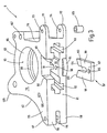
- the chain ejector can be located in the bottom of the Chain or nut housing contained opening or slot stuck. To increase the strength in this area is the opening in the bottom through a bridge divided into two sections.
- the chain ejector has in In this case the shape of a fork and overlaps in the inserted State with his two thighs this jetty.
- the fasteners can be found 127 next to the motor housing 8, while the third Fastener 128 on the of the motor housing. 8 distant side are arranged.
- the distance between the Bores 133 and 137 are the same size as the distance between the holes 126 and the holes 133.
Landscapes
- Engineering & Computer Science (AREA)
- Mechanical Engineering (AREA)
- Devices For Conveying Motion By Means Of Endless Flexible Members (AREA)
Description
Claims (23)
- Kettenzug (1)
mit einem Antriebsmotor (2), der ein Motorgehäuse (8) mit einer Stirnseite (11) aufweist, aus der eine Ankerwelle (17) auskragt,
mit einem Getriebegehäuse (3), das eine Montagefläche (33) zum Anflanschen aufweist und in dem ein Getriebe (4) enthalten ist, dessen eine Kettennuss (5) tragende Ausgangswelle (42) aus der Montagefläche (33) auskragt,
mit einem an des Getriebegehäuse (3) angeflanschten Kettennussgehäuse (6),
das aus einem festen Material besteht,
eine Montagefläche (76) zum Anflanschen an das Getriebegehäuse (3) sowie
eine im Winkel zu der Montagefläche (76) verlaufende Unterseite (81) aufweist,
das einen zu der Montagefläche (76) hin offenen Innenraum (85) für die Kettennuss (5) sowie
wenigstens eine von der Unterseite (81) zu dem Innenraum (85) führende Öffnung (89) für den Durchtritt einer Kette (74) enthält und
das mit Mitteln (127,128) zur Anbringung einer Aufhängung (141) versehen ist, und
mit einem Kettenauswerfer (97), der von der Unterseite (81) her in das Kettennussgehäuse (6) einsetzbar und demontierbar ist. - Kettenzug nach Anspruch 1, dadurch gekennzeichnet, dass das Getriebegehäuse (3) aus einem weniger festen Material besteht als das Kettennussgehäuse (6).
- Kettenzug nach Anspruch 1, dadurch gekennzeichnet, dass das Kettennußgehäuse (6) frei von einer Trennfläche ist, die parallel zu der Montagefläche (76) verläuft.
- Kettenzug nach Anspruch 1, dadurch gekennzeichnet, dass das Kettennussgehäuse (6) einstückig und unteilbar ist.
- Kettenzug nach Anspruch 1, dadurch gekennzeichnet, dass das Kettennussgehäuse (6) auf seiner Montagefläche (76) einen zylindrischen rohrförmigen Fortsatz (84) trägt und dass in dem Getriebegehäuse (3) eine zylindrische Ringnut (66) enthalten ist, in die im montierten Zustand der zylindrische rohrförmige Fortsatz (84) spielfrei hineinpasst.
- Kettenzug nach Anspruch 1, dadurch gekennzeichnet, dass die Ausgangswelle (42) des Getriebes (4) in einem Lager (64) gelagert ist und dass sich das Lager (64) zumindest mit einem axialen Abschnitt innerhalb des von der Ringnut (66) umgrenzten Bereiches befindet.
- Kettenzug nach Anspruch 1, dadurch gekennzeichnet, dass der Innenraum (85) in dem Kettennussgehäuse (6) auf der von der Montageseite (76) abliegenden Seite des Kettennussgehäuses (6) offen ist, derart, dass durch diese Öffnung die Kettennuss (5) ausbaubar ist.
- Kettenzug nach Anspruch 1, dadurch gekennzeichnet, dass der Innenraum (85) für die Kettennuss (5) eine zylindrische Bohrung (85) ist.
- Kettenzug nach Anspruch 8, dadurch gekennzeichnet, dass die zylindrische Bohrung (85) zu dem zylindrischen rohrförmigen Fortsatz (84) konzentrisch ist.
- Kettenzug nach Anspruch 8, dadurch gekennzeichnet, dass die zylindrische Bohrung (85), die den Innenraum bildet, durch das Kettennussgehäuse (6) hindurchführt.
- Kettenzug nach Anspruch 1, dadurch gekennzeichnet, dass in dem Innenraum (85) eine Kettenführungsnut (88) enthalten ist.
- Kettenzug nach Anspruch 1, dadurch gekennzeichnet, dass die Kettennuss (5) auf der Ausgangswelle (42) fliegend gelagert ist.
- Kettenzug nach Anspruch 1, dadurch gekennzeichnet, dass der Kettenauswerfer (97) in der in der Unterseite (81) befindlichen Öffnung (89) sitzt.
- Kettenzug nach Anspruch 13, dadurch gekennzeichnet, dass die auf der Unterseite (81) befindliche Öffnung (89) durch einen Steg (91) in zwei Öffnugnsabschnitte unterteilt ist.
- Kettenzug nach Anspruch 13, dadurch gekennzeichnet, dass der Kettenauswerfer (97) gegabelt ist und im eingesetzten Zustand den die Öffnung (89) in der Unterseite (81) unterteilenden Steg (91) übergreift.
- Kettenzug nach Anspruch 13, dadurch gekennzeichnet, dass der Kettenauswerfer (97) zur Befestigung an dem Kettennussgehäuse (6) eine Querbohrung (105) enthält, die bei montiertem Kettenauswerfer (97) mit einem Gewindeloch (96) in dem Kettennussgehäuse (6) fluchtet, und dass das Kettennussgehäuse (6) auf der dem Gewindeloch (96) gegenüberliegenden Seite ausgenommen ist.
- Kettenzug nach Anspruch 1, dadurch gekennzeichnet, dass das Kettennussgehäuse (6) an seiner Unterseite (81) eine Befestigungseinrichtung (115) für das gefesselte Ende einer Kette (74) bei einer zweisträngigen Ausführung aufweist.
- Kettenzug nach Anspruch 1, dadurch gekennzeichnet, dass das Motorgehäuse (8) an seiner Oberseite wenigstens ein erstes Befestigungsmittel (121) aufweist, an der ein Aufhängemittel (141) zum Aufhängen des Kettenzugs (1) anbringbar ist.
- Kettenzug nach Anspruch 1, dadurch gekennzeichnet, dass das Kettennussgehäuse (6) an seiner Oberseite (83) wenigstens ein zweites Befestigungsmittel (127,128) aufweist, an dem ein Aufhängemittel (141) zum Aufhängen des Kettenzugs (1) anbringbar ist.
- Kettenzug nach Anspruch 1, dadurch gekennzeichnet, dass die an der Oberseite (83) des Kettennussgehäuses (6) ein drittes Befestigungsmittel (127,128) vorhanden ist, wobei der Abstand zwischen der ersten (121) und der zweiten (128) Befestigungsmittel gleich dem Abstand zwischen der zweiten (127) und der dritten (128) Befestigungsmittel ist.
- Kettenzug nach Anspruch 1, dadurch gekennzeichnet, dass der Motor (2) und das Kettennussgehäuse (6) auf derselben Seite des Getriebegehäuses (3) angeflanscht sind.
- Kettenzug nach Anspruch 1, dadurch gekennzeichnet, dass der Motor (2) an seinem von der Stirnseite (11) mit der auskragenden Ankerwelle (17) abliegenden Seite mit einem Deckel (27) versehen ist, der seitlich über das Motorgehäuse (8) übersteht und dessen Fläche im Wesentlichen mit der Querschnittsfläche des Getriebegehäuses (3) übereinstimmt, die parallel zu der Montagefläche (33) des Getriebegehäuses (3) verläuft.
- Kettenzug nach Anspruch 1, dadurch gekennzeichnet, dass zwischen dem Kettennussgehäuse (6) und dem an dem Motor (2) befestigten Deckel (27) ein Raum gebildet ist, in dem sich ein Elektroanschlusskasten (7) befindet.
Applications Claiming Priority (2)
| Application Number | Priority Date | Filing Date | Title |
|---|---|---|---|
| DE19817013 | 1998-04-17 | ||
| DE19817013A DE19817013C2 (de) | 1998-04-17 | 1998-04-17 | Kettenzug |
Publications (3)
| Publication Number | Publication Date |
|---|---|
| EP0950632A2 EP0950632A2 (de) | 1999-10-20 |
| EP0950632A3 EP0950632A3 (de) | 2003-05-07 |
| EP0950632B1 true EP0950632B1 (de) | 2005-02-16 |
Family
ID=7864811
Family Applications (1)
| Application Number | Title | Priority Date | Filing Date |
|---|---|---|---|
| EP99107130A Expired - Lifetime EP0950632B1 (de) | 1998-04-17 | 1999-04-13 | Kettenzug |
Country Status (2)
| Country | Link |
|---|---|
| EP (1) | EP0950632B1 (de) |
| DE (2) | DE19817013C2 (de) |
Families Citing this family (6)
| Publication number | Priority date | Publication date | Assignee | Title |
|---|---|---|---|---|
| DE19849995A1 (de) * | 1998-10-30 | 2000-05-11 | Stahl R Foerdertech Gmbh | Hebezeug für Einschienenhängekatze mit niedriger Bauhöhe |
| DE10244864B4 (de) | 2002-09-23 | 2004-07-29 | Demag Cranes & Components Gmbh | Kettenzug, der an einem Tragelement aufgehängt werden kann |
| DE102004034589B3 (de) * | 2004-07-16 | 2006-01-05 | Demag Cranes & Components Gmbh | Kettenzug |
| DE102004040180A1 (de) * | 2004-08-18 | 2006-02-23 | R. Stahl Fördertechnik GmbH | Hebezeug mit Dehnungssensor |
| CN108285102A (zh) * | 2018-03-02 | 2018-07-17 | 浙江永天机电制造有限公司 | 单双链可切换的环链电动葫芦 |
| EP4292973A3 (de) * | 2021-09-23 | 2024-03-13 | Pewag Austria GmbH | Doppelkettenrad und kettenzug mit doppelkettenrad |
Family Cites Families (6)
| Publication number | Priority date | Publication date | Assignee | Title |
|---|---|---|---|---|
| DE3710332C1 (de) * | 1987-03-28 | 1988-07-21 | Stahl R Foerdertech Gmbh | Elektrozug |
| DE3710331A1 (de) * | 1987-03-28 | 1988-10-13 | Stahl R Foerdertech Gmbh | Elektrokettenzug |
| ES2116844B1 (es) * | 1994-07-15 | 1999-03-01 | Amenabar Axpe Javier | Polipasto. |
| DE19530891C2 (de) * | 1995-08-14 | 1999-11-18 | Mannesmann Ag | Hebezeug, das mit einem Zugmittel betrieben ist |
| DE19849693C2 (de) * | 1998-10-28 | 2001-02-22 | Stahl R Foerdertech Gmbh | Kettenzug mit Aufhängung am Kettennussgehäuse |
| DE19849995A1 (de) * | 1998-10-30 | 2000-05-11 | Stahl R Foerdertech Gmbh | Hebezeug für Einschienenhängekatze mit niedriger Bauhöhe |
-
1998
- 1998-04-17 DE DE19817013A patent/DE19817013C2/de not_active Expired - Fee Related
-
1999
- 1999-04-13 EP EP99107130A patent/EP0950632B1/de not_active Expired - Lifetime
- 1999-04-13 DE DE59911628T patent/DE59911628D1/de not_active Expired - Lifetime
Also Published As
| Publication number | Publication date |
|---|---|
| DE19817013C2 (de) | 2000-08-31 |
| DE19817013A1 (de) | 1999-10-28 |
| DE59911628D1 (de) | 2005-03-24 |
| EP0950632A3 (de) | 2003-05-07 |
| EP0950632A2 (de) | 1999-10-20 |
Similar Documents
| Publication | Publication Date | Title |
|---|---|---|
| DE69318987T2 (de) | Federkupplungseinheit mit reduzierten radialen lagerkräften | |
| DE69017300T2 (de) | Nager mit geringem Verschleiss für chirurgischen Retraktor. | |
| DE102008054842A1 (de) | Mischer | |
| DE102006036162A1 (de) | Kettennuss mit höherer Tragkraft | |
| EP0950632B1 (de) | Kettenzug | |
| DE3620705A1 (de) | Innenzahnradpumpe als schmieroelpumpe | |
| DE69506123T2 (de) | Ein getriebe aufweisender bausatz | |
| DE3041829A1 (de) | Fluessigkeitskupplung | |
| EP0729912B1 (de) | Kettenzug mit einer durch die Bremse verstellbaren Kupplung | |
| DE2121182C3 (de) | Kupplungsriemenscheibe für einen Riementrieb | |
| EP0958229B1 (de) | Seilzug mit vereinfachter montage | |
| DE2244497C3 (de) | Hydraulisch betätigbare Reibkupplung | |
| EP0997429B1 (de) | Hebezeug für Einschienenhängekatze mit niedriger Bauhöhe | |
| DE3322350C1 (de) | Kranunterflasche mit Drehantrieb | |
| DE10297127B4 (de) | Aufzugswinde | |
| DE19849693C2 (de) | Kettenzug mit Aufhängung am Kettennussgehäuse | |
| DE69402823T2 (de) | Tragevorrichtung für Rolladenantrieb | |
| DE10132551C2 (de) | Winde | |
| DE102012104181B3 (de) | Flachband für profilgezogene Rahmen- und Türbauteile | |
| DE3503342C2 (de) | ||
| DE2916034C2 (de) | Prallmühle zum Zerkleinern von Gestein o.dgl. | |
| DE102024130175A1 (de) | Gehäuse für eine Antriebsvovorrichtung zum Antreiben eines Tragmittels einer Aufzugsanlage | |
| DE2607978C3 (de) | Trommelwinde mit einem selbsthemmenden Schneckenantrieb | |
| DE4408584C2 (de) | Elektrokettenzug mit selbständiger Bremse | |
| DE8534010U1 (de) | Öffnungsabschluß mit einem auf eine Wickelwelle aufrollbares Rolltor |
Legal Events
| Date | Code | Title | Description |
|---|---|---|---|
| PUAI | Public reference made under article 153(3) epc to a published international application that has entered the european phase |
Free format text: ORIGINAL CODE: 0009012 |
|
| AK | Designated contracting states |
Kind code of ref document: A2 Designated state(s): AT BE CH CY DE DK ES FI FR GB GR IE IT LI LU MC NL PT SE |
|
| AX | Request for extension of the european patent |
Free format text: AL;LT;LV;MK;RO;SI |
|
| RIC1 | Information provided on ipc code assigned before grant |
Free format text: 7B 66D 3/22 A, 7B 66D 3/18 B |
|
| PUAL | Search report despatched |
Free format text: ORIGINAL CODE: 0009013 |
|
| AK | Designated contracting states |
Designated state(s): AT BE CH CY DE DK ES FI FR GB GR IE IT LI LU MC NL PT SE |
|
| AX | Request for extension of the european patent |
Extension state: AL LT LV MK RO SI |
|
| 17P | Request for examination filed |
Effective date: 20031001 |
|
| AKX | Designation fees paid |
Designated state(s): DE FR GB IT |
|
| 17Q | First examination report despatched |
Effective date: 20031223 |
|
| GRAP | Despatch of communication of intention to grant a patent |
Free format text: ORIGINAL CODE: EPIDOSNIGR1 |
|
| GRAS | Grant fee paid |
Free format text: ORIGINAL CODE: EPIDOSNIGR3 |
|
| GRAA | (expected) grant |
Free format text: ORIGINAL CODE: 0009210 |
|
| AK | Designated contracting states |
Kind code of ref document: B1 Designated state(s): DE FR GB IT |
|
| REG | Reference to a national code |
Ref country code: GB Ref legal event code: FG4D Free format text: NOT ENGLISH |
|
| REG | Reference to a national code |
Ref country code: IE Ref legal event code: FG4D Free format text: GERMAN |
|
| REF | Corresponds to: |
Ref document number: 59911628 Country of ref document: DE Date of ref document: 20050324 Kind code of ref document: P |
|
| GBT | Gb: translation of ep patent filed (gb section 77(6)(a)/1977) |
Effective date: 20050406 |
|
| ET | Fr: translation filed | ||
| PLBE | No opposition filed within time limit |
Free format text: ORIGINAL CODE: 0009261 |
|
| STAA | Information on the status of an ep patent application or granted ep patent |
Free format text: STATUS: NO OPPOSITION FILED WITHIN TIME LIMIT |
|
| 26N | No opposition filed |
Effective date: 20051117 |
|
| REG | Reference to a national code |
Ref country code: FR Ref legal event code: PLFP Year of fee payment: 18 |
|
| REG | Reference to a national code |
Ref country code: FR Ref legal event code: PLFP Year of fee payment: 19 |
|
| PGFP | Annual fee paid to national office [announced via postgrant information from national office to epo] |
Ref country code: FR Payment date: 20170428 Year of fee payment: 19 Ref country code: GB Payment date: 20170428 Year of fee payment: 19 Ref country code: DE Payment date: 20170420 Year of fee payment: 19 |
|
| PGFP | Annual fee paid to national office [announced via postgrant information from national office to epo] |
Ref country code: IT Payment date: 20170428 Year of fee payment: 19 |
|
| REG | Reference to a national code |
Ref country code: DE Ref legal event code: R119 Ref document number: 59911628 Country of ref document: DE |
|
| GBPC | Gb: european patent ceased through non-payment of renewal fee |
Effective date: 20180413 |
|
| PG25 | Lapsed in a contracting state [announced via postgrant information from national office to epo] |
Ref country code: DE Free format text: LAPSE BECAUSE OF NON-PAYMENT OF DUE FEES Effective date: 20181101 |
|
| PG25 | Lapsed in a contracting state [announced via postgrant information from national office to epo] |
Ref country code: GB Free format text: LAPSE BECAUSE OF NON-PAYMENT OF DUE FEES Effective date: 20180413 |
|
| PG25 | Lapsed in a contracting state [announced via postgrant information from national office to epo] |
Ref country code: FR Free format text: LAPSE BECAUSE OF NON-PAYMENT OF DUE FEES Effective date: 20180430 Ref country code: IT Free format text: LAPSE BECAUSE OF NON-PAYMENT OF DUE FEES Effective date: 20180413 |