EP0950795A2 - Outil et procédé pour tester et évaluer de formations géologiques - Google Patents
Outil et procédé pour tester et évaluer de formations géologiques Download PDFInfo
- Publication number
- EP0950795A2 EP0950795A2 EP99300512A EP99300512A EP0950795A2 EP 0950795 A2 EP0950795 A2 EP 0950795A2 EP 99300512 A EP99300512 A EP 99300512A EP 99300512 A EP99300512 A EP 99300512A EP 0950795 A2 EP0950795 A2 EP 0950795A2
- Authority
- EP
- European Patent Office
- Prior art keywords
- pressure waveform
- geological formation
- pulse generator
- pulsed pressure
- receiver probe
- Prior art date
- Legal status (The legal status is an assumption and is not a legal conclusion. Google has not performed a legal analysis and makes no representation as to the accuracy of the status listed.)
- Granted
Links
- 230000015572 biosynthetic process Effects 0.000 title claims abstract description 76
- 238000000034 method Methods 0.000 title claims abstract description 21
- 238000012360 testing method Methods 0.000 title description 9
- 238000011156 evaluation Methods 0.000 title description 3
- 239000000523 sample Substances 0.000 claims abstract description 77
- 230000035699 permeability Effects 0.000 claims description 22
- 239000012530 fluid Substances 0.000 claims description 14
- 238000011835 investigation Methods 0.000 claims description 7
- 230000003247 decreasing effect Effects 0.000 claims description 3
- 239000010453 quartz Substances 0.000 claims description 3
- VYPSYNLAJGMNEJ-UHFFFAOYSA-N silicon dioxide Inorganic materials O=[Si]=O VYPSYNLAJGMNEJ-UHFFFAOYSA-N 0.000 claims description 3
- 238000005755 formation reaction Methods 0.000 description 58
- 238000002955 isolation Methods 0.000 description 7
- 238000013459 approach Methods 0.000 description 4
- 230000008901 benefit Effects 0.000 description 4
- 238000004891 communication Methods 0.000 description 2
- 230000005284 excitation Effects 0.000 description 2
- 229930195733 hydrocarbon Natural products 0.000 description 2
- 238000011065 in-situ storage Methods 0.000 description 2
- 238000005259 measurement Methods 0.000 description 2
- 230000001052 transient effect Effects 0.000 description 2
- 239000004215 Carbon black (E152) Substances 0.000 description 1
- 230000004888 barrier function Effects 0.000 description 1
- 230000001934 delay Effects 0.000 description 1
- 238000013461 design Methods 0.000 description 1
- 150000002430 hydrocarbons Chemical class 0.000 description 1
- 125000001183 hydrocarbyl group Chemical group 0.000 description 1
- 238000004519 manufacturing process Methods 0.000 description 1
- 238000013178 mathematical model Methods 0.000 description 1
- 230000007246 mechanism Effects 0.000 description 1
- 238000012986 modification Methods 0.000 description 1
- 230000004048 modification Effects 0.000 description 1
- 230000010355 oscillation Effects 0.000 description 1
- 239000003208 petroleum Substances 0.000 description 1
- 230000008569 process Effects 0.000 description 1
- 239000011435 rock Substances 0.000 description 1
- 230000007480 spreading Effects 0.000 description 1
- 238000006467 substitution reaction Methods 0.000 description 1
- 230000002459 sustained effect Effects 0.000 description 1
- XLYOFNOQVPJJNP-UHFFFAOYSA-N water Substances O XLYOFNOQVPJJNP-UHFFFAOYSA-N 0.000 description 1
Images


Classifications
-
- E—FIXED CONSTRUCTIONS
- E21—EARTH OR ROCK DRILLING; MINING
- E21B—EARTH OR ROCK DRILLING; OBTAINING OIL, GAS, WATER, SOLUBLE OR MELTABLE MATERIALS OR A SLURRY OF MINERALS FROM WELLS
- E21B49/00—Testing the nature of borehole walls; Formation testing; Methods or apparatus for obtaining samples of soil or well fluids, specially adapted to earth drilling or wells
- E21B49/008—Testing the nature of borehole walls; Formation testing; Methods or apparatus for obtaining samples of soil or well fluids, specially adapted to earth drilling or wells by injection test; by analysing pressure variations in an injection or production test, e.g. for estimating the skin factor
-
- E—FIXED CONSTRUCTIONS
- E21—EARTH OR ROCK DRILLING; MINING
- E21B—EARTH OR ROCK DRILLING; OBTAINING OIL, GAS, WATER, SOLUBLE OR MELTABLE MATERIALS OR A SLURRY OF MINERALS FROM WELLS
- E21B49/00—Testing the nature of borehole walls; Formation testing; Methods or apparatus for obtaining samples of soil or well fluids, specially adapted to earth drilling or wells
Definitions
- This invention relates to the field of measuring characteristics of earth formations penetrated by a borehole and, more particularly, relates to a tool for and method of formation evaluation testing using pressure pulse velocity.
- Permeability can be determined by taking and analysing core samples from the formation, but this is a difficult and lengthy process. Therefore, various methods have been developed for determining the permeability of a formation in situ.
- a method of determining properties of a geological formation comprises: providing downhole a tool having a pulse generator and at least one receiver probe the or each receiver probe being spaced apart a predetermined distance from the pulse generator; generating a pulsed pressure waveform in the geological formation with the pulse generator, wherein the pulsed pressure waveform is created about a first center frequency; sensing, at a receiver probe, a first arrival time of the pulsed pressure waveform; and determining the velocity of the pulsed pressure waveform.
- a geological formation tester tool comprising: a pulse generator for generating a pulsed pressure waveform in a geological formation wherein the pulsed pressure waveform is created about a first center frequency; at least one, receiver probe the or each receiver probe being spaced apart a predetermined distance from the pulse generator and in contact with the geological formation; and a sensor operably connected to the, or each receiver probe, for sensing a first arrival time at each receiver probe, of the pulsed pressure waveform.
- the present invention provides a method and apparatus for testing geological formations using a pulsed pressure waveform created about a center frequency, preferably, a short duration sinusoidal pressure wave.
- a downhole tool including a pulse generator, for example, a formation tester reciprocating piston, and a receiver probe.
- the receiver probe is spaced apart a predetermined distance from the pulse generator and is, for instance, in contact with the geological formation.
- the pulse generator (or transmitter) generates a pulsed pressure waveform in the geological formation.
- the pulsed pressure waveform is created about a center frequency.
- a first arrival time of the pulsed pressure waveform is sensed by a sensor operably connected to the receiver probe and includes, for example, a high accuracy quartz gauge. The velocity of the pulsed pressure waveform is then determined.
- the velocity of the pulsed pressure waveform is used to determine permeability, porosity, and compressibility of the geological formation and to determine viscosity of fluids in the geological formation.
- the center frequency is, preferably, increased to allow high resolution shallow depths of investigation of the geological formation and decreased to allow deeper depths of investigation with lower resolution of the geological formation.
- a transmitter probe operably connected to the pulse generator and in contact with the geological formation, transmits the pulsed pressure waveform to the geological formation.
- the first arrival time of the pulsed pressure waveform is sensed by a sensor operably connected to the receiver probe.
- more than one receiver probe and sensor is used on the downhole tool to observe more than one arrival time at different spacings or azimuthal orientations in the borehole.
- the method and apparatus of the present invention provides a simple system for the testing of a geological formation in situ and is especially advantageous in formations having a low permeability.
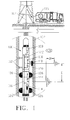
- a downhole tool 100 is lowered into a borehole 102, for example, by a cable 104 connected to a truck 106.
- Various types of downhole tool testing apparatus are well known in the art as well as various deployment methods, such as wireline or drillpipe deployment.
- the apparatus of the present invention is positioned in the borehole and deployed in the same manner.
- the apparatus of the present invention may also be permanently affixed within the borehole or be movable for a continuous measurement over a depth interval.
- An electrical motor or electrohydraulic system 108 powers the other components in the downhole tool 100. Electrical power to operate the downhole tool is transmitted through cable 104.
- the downhole tool 100 includes a receiver probe 110 and backup pads 112 which are, for example, extended from the downhole tool 100 in order to engage the walls of the borehole 102. Engagement of the receiver probe 110 with the wall of the borehole 102 is necessary to isolate the receiver probe 110 from fluids contained in the borehole 102. Backup pads 112 are used to stabilize the downhole tool 100 and insure that the receiver probe 110 remains in place against the wall of the borehole 102.
- the receiver probe 110 is spaced apart a predetermined distance from a reciprocating piston 114 (or transmitter), preferably in a range of about one-half to ten feet. (0.15 to 3m).
- the reciprocating piston 114 controls the pressure and flow rate at the receiver probe 110.
- the piston 114 is hydraulically connected to flow line tubing of the tool 116.
- Valve 124 is opened to allow communication of the pressure pulse to an opening between the packers.
- the piston 114 is designed such that it can generate a pressure pulse and therefore operate as a pulse generator.
- Packers 126 are used to isolate and center the pressure pulse between the packers within the borehole 102.
- a sensor 118 including, for example, a high accuracy quartz gauge, is connected to the receiver probe 110 and is used to record the pressure at the receiver probe 110.
- the receiver probe 110 can be isolated from the piston 114 by isolation valve 120 and the piston 114 is isolated from the borehole fluids by isolation valve 124.
- An equalization valve 122 allows borehole fluids to enter flow line tubing 116 when testing is completed.
- the downhole tool 100 is, for example, lowered into the borehole 102 on cable 104 from the truck 106.
- the electrical motor or eletrohydraulic system 108 then causes the receiver probe 110 and backup pads 112 to be extended such that they engage the borehole walls.
- the electrical motor or eletrohydraulic system 108 also causes the packers 126 to extend by inflating, which isolates an interval of formation between the packers 126.
- the piston 114 is used as a pulse generator to pulse the borehole fluids trapped between the packers 126 which immediately generates a pressure pulse in the formation adjacent to this section of the borehole.
- the isolation valves 120 and 124, respectively, and equalization valve 122 are normally open as the downhole tool 100 is lowered in the borehole 102. Prior to setting the tool, valves 120, 122 and 124 are closed to isolate the flow line 116 from wellbore fluids. The isolation valve 120 is then opened and the piston 114 withdraws a small volume of fluid from the received probe 110 to create a drawdown that is recorded by the pressure gauge sensor 118. Preferably, the drawdown is about five to ten cubic centimetres of fluid. Isolation valve 120 is then closed, creating a buildup of pressure at the receiver probe 110. The pressure drawdowns and buildups are performed to insure that the receiver probe 110 is in hydraulic communication with the formation 128.
- Isolation valve 124 is then opened and the piston 114 withdraws a larger volume of fluid, about 10 to 100 cubic centimetres from the borehole 102. Valve 124 is then closed and the pressure is allowed to build up. Valve 124 is again opened and piston 114 displaced to produce a short duration pulsed pressure waveform, for example, a pulsed well transient consisting of a short duration sinusoidal pressure waveform.
- the short duration sinusoidal pressure wave may be from about four to about ten cycles of the center frequency.
- the pulsed pressure waveform propagates through the geological formation 128.
- the sensor 118 senses a first arrival time ( ⁇ t) of the pulsed pressure waveform at the receiver probe 110.
- the short duration pulsed pressure waveform is created about a center frequency. Once the pulsed pressure waveform is generated, it propagates through the geological formation with a "group velocity" (the velocity of energy propagation for wave-like disturbances).
- the corresponding group velocity will be constant.
- the velocity of the pulsed pressure waveform is calculated by using the distance (D) of the receiver probe 110 from the pulse generator (shown herein as reciprocating piston 114), and the first arrival time ( ⁇ t) at the receiver probe 110 of the pulsed pressure waveform.
- the center frequency can also be varied and multiple regressions performed to determine all four formation parameters. For example, the center frequency can be increased to study shallow depths of investigation at higher resolution in the geological formation, and decreased to study deeper depths of investigation in the geological formation at lower resolution.
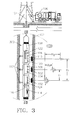
- FIG 2 illustrates a second preferred embodiment of the apparatus of the present invention, wherein downhole tool 200 is essentially identical the downhole tool 100 of Figure 1, except for the addition of a transmitter probe 202 and the absence of packers 126.
- the transmitter probe 202 is operably connected to the reciprocating piston 114 and transmits the pulsed pressure waveform to the geological formation 128.
- the transmitter probe 202 is preferably, positioned within the same azimuthal angle as the receiver probe 110 and is in contact with the wall of the borehole 102 to isolate the transmitter probe 202 from the borehole fluids.
- the receiver probe 110 and the transmitter probe 202 are spaced about one half to ten feet (0.15 to 3m) apart.
- FIG 3 illustrates a third embodiment of the apparatus of the present invention, wherein downhole tool 300 is essentially identical to the downhole tool 200 of Figure 2, except for the addition of a second receiver probe 302, and corresponding isolation valve 304 and sensor 306. More than one receiver probe can be used with the method and apparatus of the present invention.
- the receiver probes 110 and 302, respectively, are both spaced apart a predetermined distance from the transmitter probe 202. In the preferred embodiment, receiver probe 110 and receiver probe 302 are spaced apart from transmitter probe 202 by about one-half to ten feet (0.15 to 3m). Preferably, both receiver probes 110 and 302, respectively, are positioned within the same azimuthal angle as the transmitter probe 202, as illustrated.
- the receiver probes may be positioned at a different azimuthal angle.
- the first receiver can be at the same depth, but at an 180° azimuthal angle.
- the receiver probes 110 and 302, respectively, are in contact with the wall of the borehole 102 to isolate the receiver probes 110 and 302, respectively, from the borehole fluids.
- the tool is operated in the same manner as the tool in the first embodiment but the addition of more than one receiver probe provides additional data especially useful in redundancy analysis.
- the use of more than one receiver probe also provides additional data especially useful for investigation at various depths within the formation and for determining permeability barriers within the formation. In the case of two receiver probes with varying azimuthal angles, anisotropy with respect the bore hole can be determined.
- sample results are plotted in Figure 4, wherein the group velocity (C g ) in feet per second (0.3048 ms -1 ) is plotted on the vertical axis, and the permeability (k) and the center frequency in hertz (Hz) are plotted on the horizontal axes.
- the permeability (k) ranges from 0 md to 1000 md
- the frequency (f) ranges from 0 Hz to 10 Hz, an oscillation rate that is easily sustained mechanically, for example, with a formation tester piston.
- the example assumes a 20% porosity ( ⁇ ) formation and water at room temperature and pressure, having a viscosity ( ⁇ ) of 1 cp (0.001 Pa s) and a compressibility (c) of 3 x 10 6 1/psi (20.67 1/KPa).
- the velocities are found to be in the range of 10 to 200 feet per second (3 to 61 ms -1 ) and are easily measurable.
- the group velocity (C g ) versus the permeability (k) at a fixed center frequency changes approximately parabolically, illustrating that pulsed well transients can be used to resolve low permeability formation properties in a stable manner.
- the method and apparatus of the present invention can be used alone or to augment either the standard drawdown-buildup method or the phase delay method and is advantageous in low permeability formations.
- One advantage is that problems associated with phase wrapping do not arise.
- Another advantage is in the use of the first arrival times of a waveform, which are simple to detect.
- Still another advantage lies in the use of a short duration pulse, wherein the problem of "digging out” or deciphering amplitude information from a mean background field that decays geometrically, is not as severe.
- the use of a centered frequency excitation also offers the use of a simple formula for determining formation properties.
Landscapes
- Life Sciences & Earth Sciences (AREA)
- Engineering & Computer Science (AREA)
- Geology (AREA)
- Mining & Mineral Resources (AREA)
- Physics & Mathematics (AREA)
- Environmental & Geological Engineering (AREA)
- Fluid Mechanics (AREA)
- General Life Sciences & Earth Sciences (AREA)
- Geochemistry & Mineralogy (AREA)
- Chemical & Material Sciences (AREA)
- Analytical Chemistry (AREA)
- Geophysics And Detection Of Objects (AREA)
Applications Claiming Priority (2)
| Application Number | Priority Date | Filing Date | Title |
|---|---|---|---|
| US6090898A | 1998-04-15 | 1998-04-15 | |
| US60908 | 1998-04-15 |
Publications (3)
| Publication Number | Publication Date |
|---|---|
| EP0950795A2 true EP0950795A2 (fr) | 1999-10-20 |
| EP0950795A3 EP0950795A3 (fr) | 2001-08-08 |
| EP0950795B1 EP0950795B1 (fr) | 2004-11-10 |
Family
ID=22032492
Family Applications (1)
| Application Number | Title | Priority Date | Filing Date |
|---|---|---|---|
| EP19990300512 Expired - Lifetime EP0950795B1 (fr) | 1998-04-15 | 1999-01-25 | Outil et procédé pour tester et évaluer de formations géologiques |
Country Status (3)
| Country | Link |
|---|---|
| EP (1) | EP0950795B1 (fr) |
| DE (1) | DE69921722T2 (fr) |
| NO (1) | NO990872L (fr) |
Cited By (9)
| Publication number | Priority date | Publication date | Assignee | Title |
|---|---|---|---|---|
| WO2002014652A1 (fr) * | 2000-08-15 | 2002-02-21 | Baker Hughes Incorporated | Appareil d'analyse de formations souterraines dote d'orifices places dans le sens axial et de maniere helicoidale |
| WO2004074869A3 (fr) * | 2003-02-14 | 2005-01-20 | Baker Hughes Inc | Source de resonance de fond permanente |
| WO2006008172A3 (fr) * | 2004-07-21 | 2006-04-06 | Schlumberger Services Petrol | Procede et appareil d'estimation d'une distribution de permeabilite lors d'un essai de puits |
| US7823689B2 (en) | 2001-07-27 | 2010-11-02 | Baker Hughes Incorporated | Closed-loop downhole resonant source |
| CN103221635A (zh) * | 2010-11-12 | 2013-07-24 | 雪佛龙美国公司 | 用于远程感测的系统和方法 |
| US9574437B2 (en) | 2011-07-29 | 2017-02-21 | Baker Hughes Incorporated | Viscometer for downhole use |
| WO2021150276A1 (fr) * | 2020-01-24 | 2021-07-29 | Halliburton Energy Services, Inc. | Caractérisation de réservoir à perméabilité directionnelle |
| CN114922619A (zh) * | 2022-07-05 | 2022-08-19 | 浙江大学 | 一种用于井下地层测试的高集成度电液分离式小直径测压短节 |
| CN120354636A (zh) * | 2025-06-24 | 2025-07-22 | 西安石油大学 | 一种连续脉冲波在多相介质传播的模拟装置及方法 |
Families Citing this family (1)
| Publication number | Priority date | Publication date | Assignee | Title |
|---|---|---|---|---|
| CN115749754A (zh) * | 2021-09-03 | 2023-03-07 | 中国石油化工股份有限公司 | 一种井下电磁式压力脉冲发生装置及控制方法 |
Citations (1)
| Publication number | Priority date | Publication date | Assignee | Title |
|---|---|---|---|---|
| US5672819A (en) | 1996-03-13 | 1997-09-30 | Halliburton Energy Services, Inc. | Formation evaluation using phase shift periodic pressure pulse testing |
Family Cites Families (3)
| Publication number | Priority date | Publication date | Assignee | Title |
|---|---|---|---|---|
| US3962674A (en) * | 1975-02-27 | 1976-06-08 | Atlantic Richfield Company | Acoustic logging using ultrasonic frequencies |
| EP0131351A3 (fr) * | 1983-07-05 | 1986-07-23 | Mobil Oil Corporation | Procédé pour déterminer la perméabilité une formation |
| WO1997027502A1 (fr) * | 1996-01-26 | 1997-07-31 | Baker Hughes Incorporated | Systeme de forage a systeme acoustique de mesure operant pendant le forage permettant de determiner des parametres recherches et commander l'orientation du forage |
-
1999
- 1999-01-25 EP EP19990300512 patent/EP0950795B1/fr not_active Expired - Lifetime
- 1999-01-25 DE DE69921722T patent/DE69921722T2/de not_active Expired - Lifetime
- 1999-02-24 NO NO990872A patent/NO990872L/no not_active Application Discontinuation
Patent Citations (1)
| Publication number | Priority date | Publication date | Assignee | Title |
|---|---|---|---|---|
| US5672819A (en) | 1996-03-13 | 1997-09-30 | Halliburton Energy Services, Inc. | Formation evaluation using phase shift periodic pressure pulse testing |
Non-Patent Citations (1)
| Title |
|---|
| "ADVANCES IN WELL TEST ANALYSIS", SOCIETY OF PETROLEUM ENGINEERS, 1 January 1977 (1977-01-01), RICHARDSON, TEXAS, pages 111-118 |
Cited By (16)
| Publication number | Priority date | Publication date | Assignee | Title |
|---|---|---|---|---|
| WO2002014652A1 (fr) * | 2000-08-15 | 2002-02-21 | Baker Hughes Incorporated | Appareil d'analyse de formations souterraines dote d'orifices places dans le sens axial et de maniere helicoidale |
| US6585045B2 (en) | 2000-08-15 | 2003-07-01 | Baker Hughes Incorporated | Formation testing while drilling apparatus with axially and spirally mounted ports |
| CN100347406C (zh) * | 2000-08-15 | 2007-11-07 | 贝克休斯公司 | 现场确定地层参数的装置和方法 |
| US7823689B2 (en) | 2001-07-27 | 2010-11-02 | Baker Hughes Incorporated | Closed-loop downhole resonant source |
| WO2004074869A3 (fr) * | 2003-02-14 | 2005-01-20 | Baker Hughes Inc | Source de resonance de fond permanente |
| CN100344994C (zh) * | 2003-02-14 | 2007-10-24 | 贝克休斯公司 | 永久井下共振源 |
| RU2330309C2 (ru) * | 2003-02-14 | 2008-07-27 | Бейкер Хьюз Инкорпорейтед | Постоянный скважинный резонансный источник |
| WO2006008172A3 (fr) * | 2004-07-21 | 2006-04-06 | Schlumberger Services Petrol | Procede et appareil d'estimation d'une distribution de permeabilite lors d'un essai de puits |
| CN103221635A (zh) * | 2010-11-12 | 2013-07-24 | 雪佛龙美国公司 | 用于远程感测的系统和方法 |
| US9574437B2 (en) | 2011-07-29 | 2017-02-21 | Baker Hughes Incorporated | Viscometer for downhole use |
| WO2021150276A1 (fr) * | 2020-01-24 | 2021-07-29 | Halliburton Energy Services, Inc. | Caractérisation de réservoir à perméabilité directionnelle |
| US11655709B2 (en) | 2020-01-24 | 2023-05-23 | Halliburton Energy Services, Inc. | Reservoir characterization with directional permeability |
| CN114922619A (zh) * | 2022-07-05 | 2022-08-19 | 浙江大学 | 一种用于井下地层测试的高集成度电液分离式小直径测压短节 |
| CN114922619B (zh) * | 2022-07-05 | 2025-05-02 | 浙江大学 | 一种用于井下地层测试的高集成度电液分离式小直径测压短节 |
| CN120354636A (zh) * | 2025-06-24 | 2025-07-22 | 西安石油大学 | 一种连续脉冲波在多相介质传播的模拟装置及方法 |
| CN120354636B (zh) * | 2025-06-24 | 2025-08-29 | 西安石油大学 | 一种连续脉冲波在多相介质传播的模拟装置及方法 |
Also Published As
| Publication number | Publication date |
|---|---|
| DE69921722D1 (de) | 2004-12-16 |
| EP0950795A3 (fr) | 2001-08-08 |
| EP0950795B1 (fr) | 2004-11-10 |
| DE69921722T2 (de) | 2005-04-07 |
| NO990872D0 (no) | 1999-02-24 |
| NO990872L (no) | 1999-10-18 |
Similar Documents
| Publication | Publication Date | Title |
|---|---|---|
| US9477002B2 (en) | Microhydraulic fracturing with downhole acoustic measurement | |
| US5672819A (en) | Formation evaluation using phase shift periodic pressure pulse testing | |
| US11762115B2 (en) | Fracture wave depth, borehole bottom condition, and conductivity estimation method | |
| CA2501480C (fr) | Systeme et procede d'installation et d'utilisation de dispositifs dans des microforages | |
| EP1444416B1 (fr) | Utilisation de vitesses de coupe pour la prediction en temps reel du gradient de pression et de rupture de pores | |
| CA2681622C (fr) | Diagraphie sans fil de trous d'alesages remplis de fluide | |
| US7274992B2 (en) | Method for predicting pore pressure | |
| WO2009086279A2 (fr) | Mesures acoustiques avec outils d'essai et d'échantillonnage de fond | |
| WO1993007514A1 (fr) | Systeme d'exploration en temps reel a anticipation de puits d'hydrocarbures | |
| CN1019836B (zh) | 获取地层性质的方法和装置 | |
| US11230923B2 (en) | Apparatus and method for determining properties of an earth formation with probes of differing shapes | |
| GB2404983A (en) | Generating directional low frequency acoustic signals for well logging | |
| US10047601B2 (en) | Moving system | |
| EP3408497B1 (fr) | Évaluation acoustique non linéaire d'une formation | |
| Anderson et al. | The effect of crossbedding anisotropy on induction tool response | |
| GB2462181A (en) | Estimating Skin Damage | |
| EP0950795B1 (fr) | Outil et procédé pour tester et évaluer de formations géologiques | |
| US7944211B2 (en) | Characterization of formations using electrokinetic measurements | |
| Kuchuk et al. | Estimating permeability distribution from 3D interval pressure transient tests | |
| USH1156H (en) | Downhole fracture detection and characterization | |
| Marsala et al. | Sonic while drilling: Have you thought about cuttings? | |
| GB2459365A (en) | Investigating subterranean formations using electromagnetic and seismic measurements obtained simultaneously using an EM receiver for both measurements | |
| EP0587405A2 (fr) | Procédé de mesure acoustique dans un puits | |
| Lehne et al. | Comparison between Stoneley, NMR, and core-derived permeabilities | |
| Sinha et al. | Applications of sonics and ultrasonics in geophysical prospecting |
Legal Events
| Date | Code | Title | Description |
|---|---|---|---|
| PUAI | Public reference made under article 153(3) epc to a published international application that has entered the european phase |
Free format text: ORIGINAL CODE: 0009012 |
|
| AK | Designated contracting states |
Kind code of ref document: A2 Designated state(s): DE FR GB |
|
| AX | Request for extension of the european patent |
Free format text: AL;LT;LV;MK;RO;SI |
|
| PUAL | Search report despatched |
Free format text: ORIGINAL CODE: 0009013 |
|
| AK | Designated contracting states |
Kind code of ref document: A3 Designated state(s): AT BE CH CY DE DK ES FI FR GB GR IE IT LI LU MC NL PT SE |
|
| AX | Request for extension of the european patent |
Free format text: AL;LT;LV;MK;RO;SI |
|
| RIC1 | Information provided on ipc code assigned before grant |
Free format text: 7E 21B 47/14 A, 7E 21B 49/00 B, 7G 01V 1/44 B |
|
| 17P | Request for examination filed |
Effective date: 20010926 |
|
| AKX | Designation fees paid |
Free format text: DE FR GB |
|
| GRAP | Despatch of communication of intention to grant a patent |
Free format text: ORIGINAL CODE: EPIDOSNIGR1 |
|
| GRAS | Grant fee paid |
Free format text: ORIGINAL CODE: EPIDOSNIGR3 |
|
| GRAA | (expected) grant |
Free format text: ORIGINAL CODE: 0009210 |
|
| AK | Designated contracting states |
Kind code of ref document: B1 Designated state(s): DE FR GB |
|
| REG | Reference to a national code |
Ref country code: GB Ref legal event code: FG4D |
|
| REF | Corresponds to: |
Ref document number: 69921722 Country of ref document: DE Date of ref document: 20041216 Kind code of ref document: P |
|
| ET | Fr: translation filed | ||
| PLBE | No opposition filed within time limit |
Free format text: ORIGINAL CODE: 0009261 |
|
| STAA | Information on the status of an ep patent application or granted ep patent |
Free format text: STATUS: NO OPPOSITION FILED WITHIN TIME LIMIT |
|
| 26N | No opposition filed |
Effective date: 20050811 |
|
| REG | Reference to a national code |
Ref country code: DE Ref legal event code: R082 Ref document number: 69921722 Country of ref document: DE Representative=s name: WEISSE, RENATE, DIPL.-PHYS. DR.-ING., DE |
|
| PGFP | Annual fee paid to national office [announced via postgrant information from national office to epo] |
Ref country code: GB Payment date: 20131227 Year of fee payment: 16 |
|
| PGFP | Annual fee paid to national office [announced via postgrant information from national office to epo] |
Ref country code: DE Payment date: 20140131 Year of fee payment: 16 |
|
| PGFP | Annual fee paid to national office [announced via postgrant information from national office to epo] |
Ref country code: FR Payment date: 20131223 Year of fee payment: 16 |
|
| REG | Reference to a national code |
Ref country code: DE Ref legal event code: R119 Ref document number: 69921722 Country of ref document: DE |
|
| GBPC | Gb: european patent ceased through non-payment of renewal fee |
Effective date: 20150125 |
|
| PG25 | Lapsed in a contracting state [announced via postgrant information from national office to epo] |
Ref country code: GB Free format text: LAPSE BECAUSE OF NON-PAYMENT OF DUE FEES Effective date: 20150125 Ref country code: DE Free format text: LAPSE BECAUSE OF NON-PAYMENT OF DUE FEES Effective date: 20150801 |
|
| REG | Reference to a national code |
Ref country code: FR Ref legal event code: ST Effective date: 20150930 |
|
| PG25 | Lapsed in a contracting state [announced via postgrant information from national office to epo] |
Ref country code: FR Free format text: LAPSE BECAUSE OF NON-PAYMENT OF DUE FEES Effective date: 20150202 |