EP0950841A1 - Raccord de tuyaux détachable - Google Patents
Raccord de tuyaux détachable Download PDFInfo
- Publication number
- EP0950841A1 EP0950841A1 EP99105517A EP99105517A EP0950841A1 EP 0950841 A1 EP0950841 A1 EP 0950841A1 EP 99105517 A EP99105517 A EP 99105517A EP 99105517 A EP99105517 A EP 99105517A EP 0950841 A1 EP0950841 A1 EP 0950841A1
- Authority
- EP
- European Patent Office
- Prior art keywords
- pipe connection
- chamber
- flange
- disc
- connection according
- Prior art date
- Legal status (The legal status is an assumption and is not a legal conclusion. Google has not performed a legal analysis and makes no representation as to the accuracy of the status listed.)
- Granted
Links
Images
Classifications
-
- F—MECHANICAL ENGINEERING; LIGHTING; HEATING; WEAPONS; BLASTING
- F01—MACHINES OR ENGINES IN GENERAL; ENGINE PLANTS IN GENERAL; STEAM ENGINES
- F01N—GAS-FLOW SILENCERS OR EXHAUST APPARATUS FOR MACHINES OR ENGINES IN GENERAL; GAS-FLOW SILENCERS OR EXHAUST APPARATUS FOR INTERNAL-COMBUSTION ENGINES
- F01N13/00—Exhaust or silencing apparatus characterised by constructional features
- F01N13/18—Construction facilitating manufacture, assembly, or disassembly
- F01N13/1805—Fixing exhaust manifolds, exhaust pipes or pipe sections to each other, to engine or to vehicle body
-
- F—MECHANICAL ENGINEERING; LIGHTING; HEATING; WEAPONS; BLASTING
- F01—MACHINES OR ENGINES IN GENERAL; ENGINE PLANTS IN GENERAL; STEAM ENGINES
- F01N—GAS-FLOW SILENCERS OR EXHAUST APPARATUS FOR MACHINES OR ENGINES IN GENERAL; GAS-FLOW SILENCERS OR EXHAUST APPARATUS FOR INTERNAL-COMBUSTION ENGINES
- F01N13/00—Exhaust or silencing apparatus characterised by constructional features
- F01N13/18—Construction facilitating manufacture, assembly, or disassembly
- F01N13/1805—Fixing exhaust manifolds, exhaust pipes or pipe sections to each other, to engine or to vehicle body
- F01N13/1827—Sealings specially adapted for exhaust systems
-
- F—MECHANICAL ENGINEERING; LIGHTING; HEATING; WEAPONS; BLASTING
- F01—MACHINES OR ENGINES IN GENERAL; ENGINE PLANTS IN GENERAL; STEAM ENGINES
- F01N—GAS-FLOW SILENCERS OR EXHAUST APPARATUS FOR MACHINES OR ENGINES IN GENERAL; GAS-FLOW SILENCERS OR EXHAUST APPARATUS FOR INTERNAL-COMBUSTION ENGINES
- F01N2450/00—Methods or apparatus for fitting, inserting or repairing different elements
- F01N2450/24—Methods or apparatus for fitting, inserting or repairing different elements by bolts, screws, rivets or the like
Definitions
- the invention relates to a detachable pipe connection for sealing exhaust pipes of internal combustion engines, with a flange with a chamber for receiving a Beaded ring-shaped disc.
- Exhaust pipes from internal combustion engines usually consist of several Single pipes that are directly connected to each other on the vehicle and against Leakage of media to be sealed. It becomes like a sleeve insertable pipes are used, which are attached via pipe clamps. Moreover, it is known to arrange flange surfaces at the pipe ends, between which seals are arranged and z. B. screws are connected.
- DE OS 1959 666 shows a detachable pipe connection with flange surfaces, in which an annular helical spring is axially clamped between the flange surfaces.
- the coil spring seals directly on the pipe surfaces.
- an elastic sealing ring made of elastomeric material can be connected upstream of the coil spring.
- Exhaust systems in modern engines have to be designed for ever higher temperatures and longer operating times. Sealing bodies made of non-metallic materials no longer meet the loads. Sealing directly on the exhaust pipes also often poses problems because the pipes do not have the necessary surface topography. Inadequate sealing means that oxygen gets into the exhaust gas flow. This oxygen enrichment is detected by the engine electronics and immediately causes fuel enrichment in the fuel-air mixture. As a result, more air-polluting substances flow into the atmosphere.
- a 1 is a flange seal made of metal for high pressures and Temperatures.
- a disc made of coaxially corrugated sheet metal has flanged soft metal sealing washers at the two end regions. When the flanges are screwed together, the soft metal is plastically deformed and seals in the chamber.
- the disadvantage of this system is that after each Loosening the connection a new washer must be used.
- the invention has for its object a pipe connection for sealing To create exhaust pipes that can be used at high temperatures and also after repeated loosening of the connecting parts can still be used so that a Micro-sealing is guaranteed.
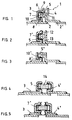
- FIG. 1 shows a pipe connection 1 according to the invention
- the flange 3 has an annular chamber 5, in which one with Beads 6 provided disc 7 is arranged.
- the disc 7 lies on the flanks 8, 9 and at the bottom 10 of the chamber 5.
- the beads 6 are both in the area of the bottom 10 also provided in the area of the flanks 8.9.
- the counter flange 4 has an axially directed projection 11, which is dimensioned such that it can be inserted into the chamber 5 and the beads axially and radially with a defined sealing pressure for bearing against both the plug body 11 and the bottom 10 and on the flanks 8 , 9 brings.
- suitable fastening means for example a screw connection
- the flanks can be joined together and a seal is created via the beads 6 in both the radial and the axial direction.
- This series connection of beads 6 creates several sealing zones, which ensures micro-sealing, regardless of the surface properties of the pipes 2, 2 '. As shown in FIG.
- FIG. 2 shows an alternative embodiment of the invention, in which a ring 14 is pressed into the chamber 5.
- the counter flange 4 ' can be formed symmetrically to the flange 3.
- a disk 7 'according to FIG. 2 has been used, which interacts with the flanges 3, 4 disclosed in FIG.
- the pipe connection can Assembly work on the motor vehicle can be easily solved and reassembled.
Landscapes
- Engineering & Computer Science (AREA)
- Chemical & Material Sciences (AREA)
- Combustion & Propulsion (AREA)
- Mechanical Engineering (AREA)
- General Engineering & Computer Science (AREA)
- Exhaust Silencers (AREA)
- Flanged Joints, Insulating Joints, And Other Joints (AREA)
- Gasket Seals (AREA)
- Joints With Pressure Members (AREA)
Applications Claiming Priority (2)
| Application Number | Priority Date | Filing Date | Title |
|---|---|---|---|
| DE19816862 | 1998-04-16 | ||
| DE19816862A DE19816862C2 (de) | 1998-04-16 | 1998-04-16 | Lösbare Rohrverbindung |
Publications (2)
| Publication Number | Publication Date |
|---|---|
| EP0950841A1 true EP0950841A1 (fr) | 1999-10-20 |
| EP0950841B1 EP0950841B1 (fr) | 2003-07-30 |
Family
ID=7864708
Family Applications (1)
| Application Number | Title | Priority Date | Filing Date |
|---|---|---|---|
| EP99105517A Expired - Lifetime EP0950841B1 (fr) | 1998-04-16 | 1999-03-18 | Raccord de tuyaux détachable |
Country Status (3)
| Country | Link |
|---|---|
| EP (1) | EP0950841B1 (fr) |
| DE (2) | DE19816862C2 (fr) |
| ES (1) | ES2201586T3 (fr) |
Cited By (1)
| Publication number | Priority date | Publication date | Assignee | Title |
|---|---|---|---|---|
| WO2008128778A1 (fr) * | 2007-04-24 | 2008-10-30 | Reinz-Dichtungs-Gmbh | Joint plat tridimensionnel |
Families Citing this family (1)
| Publication number | Priority date | Publication date | Assignee | Title |
|---|---|---|---|---|
| DE102006045584A1 (de) * | 2006-09-27 | 2008-05-15 | Elringklinger Ag | Dichtungssystem |
Citations (5)
| Publication number | Priority date | Publication date | Assignee | Title |
|---|---|---|---|---|
| FR868188A (fr) * | 1940-12-19 | 1941-12-23 | Cfcmug | Dispositif de joint étanche permettant l'assemblage des différentes parties d'une même capacité |
| FR1409193A (fr) * | 1964-09-29 | 1965-08-20 | Babcock & Wilcox Co | Joint détanchéité |
| DE1959666A1 (de) * | 1969-11-28 | 1971-06-03 | Goetzewerke | Rohrverbindung |
| FR2327459A1 (fr) * | 1975-10-09 | 1977-05-06 | Klinger Ag | Dispositif d'etancheite pour organes d'arret |
| EP0303068A2 (fr) * | 1987-08-13 | 1989-02-15 | Feodor Burgmann Dichtungswerke GmbH & Co. | Connexion de brides avec une garniture à multiples couches |
Family Cites Families (5)
| Publication number | Priority date | Publication date | Assignee | Title |
|---|---|---|---|---|
| US1178714A (en) * | 1915-07-12 | 1916-04-11 | Stanley Griffin | Coupling-joint for pipes and other connections. |
| US1490805A (en) * | 1921-07-18 | 1924-04-15 | John J Divekey | Closet flange |
| US1715854A (en) * | 1923-03-06 | 1929-06-04 | Standard Dev Co | Fluid-tight joint |
| DE647885C (de) * | 1932-12-20 | 1937-07-15 | Otto Dietrich Rohrleitungsbau | Selbstdichtende Rohrverbindung mit Flanschen, Bunden o. dgl. |
| DE19503285A1 (de) * | 1995-02-02 | 1996-08-08 | Rudolf P Fritsch | Statische Dichtung |
-
1998
- 1998-04-16 DE DE19816862A patent/DE19816862C2/de not_active Expired - Fee Related
-
1999
- 1999-03-18 EP EP99105517A patent/EP0950841B1/fr not_active Expired - Lifetime
- 1999-03-18 ES ES99105517T patent/ES2201586T3/es not_active Expired - Lifetime
- 1999-03-18 DE DE59906407T patent/DE59906407D1/de not_active Expired - Lifetime
Patent Citations (5)
| Publication number | Priority date | Publication date | Assignee | Title |
|---|---|---|---|---|
| FR868188A (fr) * | 1940-12-19 | 1941-12-23 | Cfcmug | Dispositif de joint étanche permettant l'assemblage des différentes parties d'une même capacité |
| FR1409193A (fr) * | 1964-09-29 | 1965-08-20 | Babcock & Wilcox Co | Joint détanchéité |
| DE1959666A1 (de) * | 1969-11-28 | 1971-06-03 | Goetzewerke | Rohrverbindung |
| FR2327459A1 (fr) * | 1975-10-09 | 1977-05-06 | Klinger Ag | Dispositif d'etancheite pour organes d'arret |
| EP0303068A2 (fr) * | 1987-08-13 | 1989-02-15 | Feodor Burgmann Dichtungswerke GmbH & Co. | Connexion de brides avec une garniture à multiples couches |
Cited By (1)
| Publication number | Priority date | Publication date | Assignee | Title |
|---|---|---|---|---|
| WO2008128778A1 (fr) * | 2007-04-24 | 2008-10-30 | Reinz-Dichtungs-Gmbh | Joint plat tridimensionnel |
Also Published As
| Publication number | Publication date |
|---|---|
| ES2201586T3 (es) | 2004-03-16 |
| DE59906407D1 (de) | 2003-09-04 |
| DE19816862A1 (de) | 1999-10-28 |
| EP0950841B1 (fr) | 2003-07-30 |
| DE19816862C2 (de) | 2000-09-21 |
Similar Documents
| Publication | Publication Date | Title |
|---|---|---|
| DE29907590U1 (de) | Abkoppelelement zur Abkopplung von Schwingungen | |
| DE202008010025U1 (de) | Metallische Dichtung, insbesondere Abgaskrümmerdichtung | |
| DE2701022A1 (de) | Gasdichte rohrverbindung, insbesondere fuer eine abgasleitung | |
| EP1087172B1 (fr) | Dispositif pour fermer l'extrémité d'un tube | |
| EP0087702A1 (fr) | Raccord de tuyaux | |
| EP0950841B1 (fr) | Raccord de tuyaux détachable | |
| AT501851B1 (de) | Verbindung von leitungen für hochdruckmedien | |
| DE602005004591T2 (de) | Rohrverbindung, Dichtung und Herstellungsverfahren der Rohrverbindung | |
| EP2206900B1 (fr) | Bride de liaison | |
| DE102014011606B4 (de) | Abgassystem für eine Brennkraftmaschine | |
| EP1231364A1 (fr) | Conduite d'échappement pour moteur à combustion interne ayant une couche d'air isolante | |
| DE3603498C2 (fr) | ||
| DE102016100598A1 (de) | Anordnung zum fluiddichten Anschließen einer Rohrleitung sowie Ausgleichselement für die Anordnung | |
| DE19646883B4 (de) | Abgaskrümmerstoßverbindung | |
| DE20108840U1 (de) | Verbindung für Rohre oder Rohrformteile | |
| DE19712403C1 (de) | Rohrverbindung | |
| DE102006043864A1 (de) | Vorrichtung zur gasdichten Montage eines Krümmerrohrs | |
| DE202005019046U1 (de) | Vorrichtung zur gasdichten Montage eines Krümmerrohrs | |
| EP1783413B1 (fr) | Dispositif pour raccorder les bouts d'un tuyau métallique ondulé hélicoïdalement avec un embout | |
| DE202006016187U1 (de) | Ladeluftschlauchadapter | |
| DE102004051680C5 (de) | Anordnung zur Befestigung eines Abgaskrümmers | |
| DE19646125A1 (de) | Rohrverbindung | |
| DE202007016256U1 (de) | Flexibles Leitungselement für eine Abgasanlage | |
| AT526935B1 (de) | Steckverbinder | |
| DE102022120822B3 (de) | Rohrverbindungsanordnung mit einem Mantelrohr und Brennkraftmaschine mit einer solchen Rohrverbindungsanordnung |
Legal Events
| Date | Code | Title | Description |
|---|---|---|---|
| PUAI | Public reference made under article 153(3) epc to a published international application that has entered the european phase |
Free format text: ORIGINAL CODE: 0009012 |
|
| AK | Designated contracting states |
Kind code of ref document: A1 Designated state(s): DE ES FR GB IT |
|
| AX | Request for extension of the european patent |
Free format text: AL;LT;LV;MK;RO;SI |
|
| 17P | Request for examination filed |
Effective date: 19991118 |
|
| AKX | Designation fees paid |
Free format text: DE ES FR GB IT |
|
| GRAH | Despatch of communication of intention to grant a patent |
Free format text: ORIGINAL CODE: EPIDOS IGRA |
|
| GRAH | Despatch of communication of intention to grant a patent |
Free format text: ORIGINAL CODE: EPIDOS IGRA |
|
| GRAA | (expected) grant |
Free format text: ORIGINAL CODE: 0009210 |
|
| AK | Designated contracting states |
Designated state(s): DE ES FR GB IT |
|
| REG | Reference to a national code |
Ref country code: GB Ref legal event code: FG4D Free format text: NOT ENGLISH |
|
| REF | Corresponds to: |
Ref document number: 59906407 Country of ref document: DE Date of ref document: 20030904 Kind code of ref document: P |
|
| GBT | Gb: translation of ep patent filed (gb section 77(6)(a)/1977) |
Effective date: 20031025 |
|
| REG | Reference to a national code |
Ref country code: ES Ref legal event code: FG2A Ref document number: 2201586 Country of ref document: ES Kind code of ref document: T3 |
|
| ET | Fr: translation filed | ||
| PLBE | No opposition filed within time limit |
Free format text: ORIGINAL CODE: 0009261 |
|
| STAA | Information on the status of an ep patent application or granted ep patent |
Free format text: STATUS: NO OPPOSITION FILED WITHIN TIME LIMIT |
|
| 26N | No opposition filed |
Effective date: 20040504 |
|
| PGFP | Annual fee paid to national office [announced via postgrant information from national office to epo] |
Ref country code: ES Payment date: 20090323 Year of fee payment: 11 |
|
| PGFP | Annual fee paid to national office [announced via postgrant information from national office to epo] |
Ref country code: GB Payment date: 20090206 Year of fee payment: 11 |
|
| GBPC | Gb: european patent ceased through non-payment of renewal fee |
Effective date: 20100318 |
|
| PG25 | Lapsed in a contracting state [announced via postgrant information from national office to epo] |
Ref country code: GB Free format text: LAPSE BECAUSE OF NON-PAYMENT OF DUE FEES Effective date: 20100318 |
|
| REG | Reference to a national code |
Ref country code: ES Ref legal event code: FD2A Effective date: 20110419 |
|
| PG25 | Lapsed in a contracting state [announced via postgrant information from national office to epo] |
Ref country code: ES Free format text: LAPSE BECAUSE OF NON-PAYMENT OF DUE FEES Effective date: 20110404 |
|
| PG25 | Lapsed in a contracting state [announced via postgrant information from national office to epo] |
Ref country code: ES Free format text: LAPSE BECAUSE OF NON-PAYMENT OF DUE FEES Effective date: 20100319 |
|
| PGFP | Annual fee paid to national office [announced via postgrant information from national office to epo] |
Ref country code: FR Payment date: 20120328 Year of fee payment: 14 |
|
| PGFP | Annual fee paid to national office [announced via postgrant information from national office to epo] |
Ref country code: IT Payment date: 20120323 Year of fee payment: 14 |
|
| REG | Reference to a national code |
Ref country code: FR Ref legal event code: ST Effective date: 20131129 |
|
| PG25 | Lapsed in a contracting state [announced via postgrant information from national office to epo] |
Ref country code: FR Free format text: LAPSE BECAUSE OF NON-PAYMENT OF DUE FEES Effective date: 20130402 |
|
| PG25 | Lapsed in a contracting state [announced via postgrant information from national office to epo] |
Ref country code: IT Free format text: LAPSE BECAUSE OF NON-PAYMENT OF DUE FEES Effective date: 20130318 |
|
| PGFP | Annual fee paid to national office [announced via postgrant information from national office to epo] |
Ref country code: DE Payment date: 20150331 Year of fee payment: 17 |
|
| REG | Reference to a national code |
Ref country code: DE Ref legal event code: R119 Ref document number: 59906407 Country of ref document: DE |
|
| PG25 | Lapsed in a contracting state [announced via postgrant information from national office to epo] |
Ref country code: DE Free format text: LAPSE BECAUSE OF NON-PAYMENT OF DUE FEES Effective date: 20161001 |